
Summary of Contents for DAVIS eVO DVC10-A7KGP1E
- Page 1 DAVISeVO EV AC Charger Installation and Operation Manual DVC10-A7KGP1E DVC10-A11KGP1E DVC10-A22KGP1E Document version V1.0...
- Page 2 Disclaimer of Warranties and Limitation of Liabilities The specifications, illustrations, and information in this manual are based on the latest data provided by our technicians. DAVIS LIGHTING reserves the right to update the manual without prior notice. While every effort has been made to ensure the accuracy of the information in this manual, including product specifications, features, and illustrations, no guarantee is provided regarding the completeness of its content.
- Page 3 Safety Instructions The following safety warnings cover most situations that DAVIS LIGHTING is aware of. However, DAVIS LIGHTING cannot anticipate or advise on all possible warnings. It is crucial to verify the operational procedures to ensure both your personal safety and the proper functioning of the charger.
-
Page 4: Table Of Contents
6. Charger power supply operation .........................18 6.1 Power on operation ............................18 6.2 Close the Charger power switch ........................19 6.3 Power-off operation ............................19 7. Maintenance and fault diagnosis .........................20 7.1 Maintenance ...............................20 7.2 Fault diagnosis ............................20 8. DAVIS LIGHTING Service ...........................22... -
Page 5: About This Manual
1.6 General Introduction The DAVIS DVC10 series AC charger is designed for charging electric vehicles or plug-in hybrid electric vehicles in your home or apartment. Our chargers provide safe, reliable, fast, and intelligent charging solutions. The primary difference between the DAVIS 7KW, 11KW, and 22KW EV AC chargers is the electrical installation type, with the latter two (11KW and 22KW) supporting 400V voltage input. -
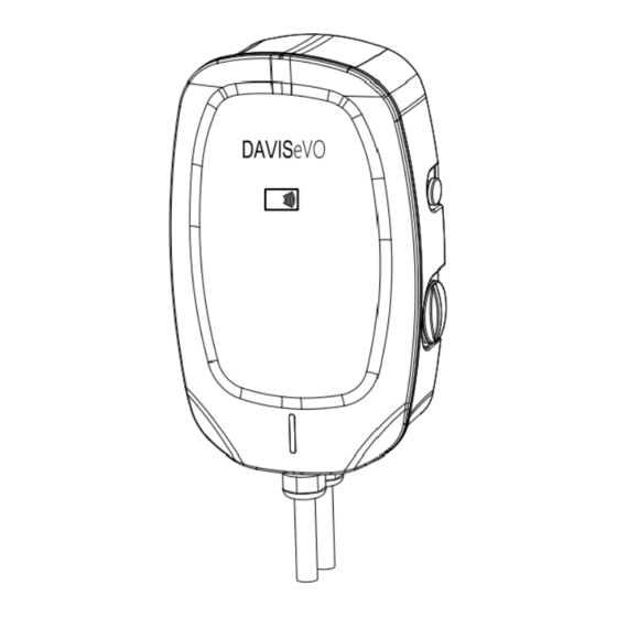
Page 6: Product Overview
Alternating current power supply Direct current power supply Electromagnetic compatibility Electric vehicle EVSE Electric vehicle power supply Charger RFID Radio frequency identification Protective ground Note: All terms may not be explained in this manual, which may help the engineer understand the operation about the Charger. 1.8 Product overview Charger main body cover Front cover plate... -
Page 7: Led Indicator
1.8 Product Overview Mounting bracket Rear plate Wall installation hole AC wire connector Width of the charger Depth of the charger Height of the charger X: 230 mm Y: 115 mm Z: 375 mm 1.9 LED indicator Solid Green The charger is on standby / A charging session has ended Green Not illuminated The charger is off... -
Page 8: Specifications
2. Specifications 2.1 Product name plate Product name Protection degree Product model Implementation standards Input characteristics Production date and bar code Output characteristics Note: The data in the figure is only a reference and does not represent the physical nameplate of the product. To view the applicable data, find the nameplate on the charger. -
Page 9: Product Technical Parameters
2.2 Product technical parameters Electrical parameters Model DVC10-A7KGP1E DVC10-A11KGP1E DVC10-A22KGP1E Comment Note: The product Input Single-phase three- Three-phase five-wire is suitable for T-N mode wire system. Note: The product Voltage works normally 220-240Vac 360-440Vac range within this voltage range. Input Frequency parameters 45~65 Hz... - Page 10 Resistance Output ≤ 90%,the insulation resistance between each live circuit and between the Input to PE live circuits and the ground is not less than 10MΩ at 1000V DC voltage. Output to PE Input to AC2500V/1min/10mA Output Input to PE AC2500V/1min/10mA Withstand Output...
-
Page 11: Preparation For Charger Installation
3. Preparation for charger installation 3.1 General requirements • Obtain permission to install this charger in accordance with local regulations. • The AC power supply is accessible at the installation location. • Ensure that the power cable is disconnected during installation. 3.2. -
Page 12: Electrical Installation Of Charger
4. Electrical installation of charger 4.1 General Specification Before performing any electrical installations, ensure that you have a clear understanding of the following electrical regulations for the charger: Wiring terminal definition Cable requirement Note: 1. For the DVC10-A7KGP1E charger, the maximum continuous working current is 32A, and the cable must meet these requirements. -
Page 13: Electrical Installation Procedure
Note: 1. For the DVC10-A11KGP1E charger, the maximum continuous working current is 16A, and the cable should meet the above requirements. It is recommended to use a 12 AWG cable with a 600Vac withstand voltage rating. 2. For the DVC10-A22KGP1E charger, the maximum continuous working current is 32A, and the cable should meet the requirements outlined above. - Page 14 Charger AC input cable connection • Use a screwdriver to unscrew and loosen the fixing screws on the wiring terminals. • Attach the cable to the appropriate terminal port, following the installation diagram for guidance. Then, use a screwdriver to secure the screws to the specified torque level. (Recommended torque: Max 2 Nm. / 10.6 Lbf.in) •...
-
Page 15: Mechanical Installation Of The Charger
• Before installing the maintenance cover, check the waterproof seal strip to ensure it is correctly installed in the groove. • Reattach the maintenance cover plate and securely fasten the fixing screws with a screwdriver. Note: Please refrain from removing the waterproof sealing strip during installation. Doing so may compromise the charger's waterproofing, allowing water to enter and potentially causing short circuits and damage. -
Page 16: General Specification
5.2 General Specification • The engineer or user should supply four expansion bolts measuring M6x50mm, with a load-bearing capacity of at least 10kg. • Refer to the detailed charger installation space requirements as follows: Specific technical data: parameter Recommended Specification (mm) ≥300 B (Indoor installation) ≥900... -
Page 17: Support Rear Plate Mounting
5.3 Support rear plate mounting • After selecting the installation location, drill the holes on the wall, and the holes aperture should be suitable for the M6 x 50 type expansion bolt. This data can be obtained from the technical parameters of the expansion bolt. Fixing the installation rear plate to the wall with the expansion bolt. -
Page 18: Installation The Whole Charger
M4 x 10 screw 5.5 Installation the whole Charger • Install the charger into the rear plate from top to bottom, aligning it with the mounting bracket and the mounting holes. • Use a screwdriver to secure the mounting bracket to the location where it connects with the rear plate. Installation schematic diagram of the support hanging ear installation Mounting Screw Mounting bracket... -
Page 19: Close The Charger Power Switch
6.2 Close the Charger power switch • Turn and unscrew the maintenance cover on the right side to visually inspect the internal charger-residual current protector. Refer to the schematic diagram for detailed instructions. • Before closing the residual current charger, press the "RESET" button to reset it; otherwise, the closing operation will be invalid. -
Page 20: Maintenance And Fault Diagnosis
7. Maintenance and fault diagnosis 7.1 Maintenance • Users shall conduct maintenance inspection of the charger, including the following items: • Check whether the charger power supply cable and charging gun cable are damaged. • Inspect the charger shell for any signs of damage. If you notice substantial damage, stop using the charger immediately. - Page 21 Issue or Potential factor Possible solutions malfunction The residual current device is not switched Switch on the residual current device Charger not starting Incorrect phase sequence wiring. Check the AC wiring connection. 1. Check whether the vehicle load matches the charger. Charger 2.
-
Page 22: Davis Lighting Service
Interruption in the connection between the charger and the router. 8. DAVIS LIGHTING Service If you have any questions about the product, please contact the manufacturer's local supplier representative or the manufacturer's after-sales service. When seeking information or applying for service support, please provide the following information: •...
Need help?
Do you have a question about the eVO DVC10-A7KGP1E and is the answer not in the manual?
Questions and answers