
Related Manuals for Carrier 61CW-Z


Summary of Contents for Carrier 61CW-Z
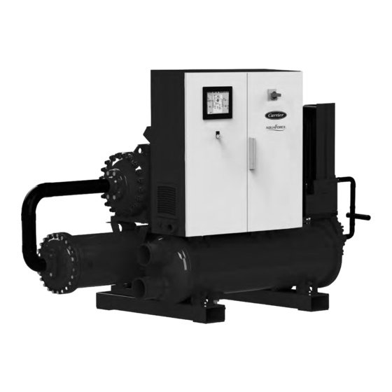
- Page 1 I N S TA L L AT I O N , O P E R AT I O N A N D M A I N T E N A N C E I N S T R U C T I O N S Heat pump operating manual 61CW-Z Original document...
-
Page 2: Table Of Contents
2.4 - Unauthorised modifications ............................... 4 2.5 - Intended use....................................4 3 - DESCRIPTION ....................................5 3.1 - Function..................................... 5 3.2 - Layout of appliance types 61CW-Z ............................5 3.3 - Pipework....................................6 3.4 - Safety equipment ..................................7 3.5 - Guarantee ....................................7 4 - INSTALLATION ..................................... 8 4.1 ... -
Page 3: General Information
1 - GENERAL INFORMATION The language of the original operating manual is German. This manual in any other language is a translation of the original operating manual. Close observation of this document is a prerequisite for the intended use and correct operation of the product. The operating manual corresponds to the product version and the safety regulations and standards applicable at the time of printing. A copy of the EC declaration of conformity is part of this operating manual. Any modification of the machine not authorised by the manufacturer (CARRIER) or non-compliance with the product or personnel safety instructions in the operating manual will invalidate this declaration. BEFORE INSTALLING AND COMMISSIONING THE HEAT PUMP, READ THIS OPERATING MANUAL IN FULL. -
Page 4: Safety
In particular, failure to observe such information can result in the safety declarations. Modifications to the product are only following risks: permissible following consultation with the manufacturer. For spare ■ Danger to individuals due to escaping hot water/fluid parts, please contact CARRIER. Use of other parts voids the ■ Danger to individuals due to electrical current liability for any consequential losses. ■ Danger of environmental pollution due to leaking fluids 2.5 - Intended use ■ Damage to the system or system components through ... -
Page 5: Description
3 - DESCRIPTION 3.1 - Function Heat pumps of types 61CW-Z are compact units for indoor installation. Heat is drawn from a water or brine circuit at 8 to 20°C (e.g. process coolant, return coolant, etc.). The heat pumps can be used to provide heating and process heat up to 92 °C. 3.2 - Layout of appliance types 61CW-Z Fig. 1: Basic principle of a heat pump Increased heat transfer through higher mass flow rate. ECO-HX 3.2.1 - Thermodynamic circuit 3.2.3 - Frame This consists of: The heat pump components are mounted on a solid frame, partly self-supporting on the shell and tube heat exchangers. Shell and tube heat exchanger as evaporator, compressor, shell and tube heat exchanger as condenser, plate heat exchanger as 3.2.4 - Sound insulating enclosure oil cooler, plate heat exchanger as economiser, oil separator, oil ... -
Page 6: Pipework
The lines are intended only for conveying the refrigerant within the heat pump. 3.3.2 - Operating media The pipelines listed under 3.4.1.1 are filled with the fluid indicated on the respective type plate and must only be filled with this fluid. Use of any other substance immediately voids the CARRIER warranty and any claims for damage. 3.3.3 - Application range The required ambient conditions are described in section 4.3 (installation location). ... -
Page 7: Safety Equipment
3 - DESCRIPTION 3.4 - Safety equipment 3.5 - Guarantee CARRIER high temperature heat pumps of series c2 are equipped All CARRIER heat pumps are covered by a guarantee of 24 with the following safety features: months, provided the installation and operating conditions are adhered to and the system datasheets have been completed. The ■ Refrigerant circuit safety valves system design and layout must comply with the applicable ... -
Page 8: Installation
4.5 - Heating connection (WNA) transport the secured appliance carefully at an angle of up to 30°. Should its transport require greater angles of It is the system installer’s responsibility to size and route the heat inclination, consult CARRIER in advance. During both sink system within the CARRIER guidelines. transport and storage, ambient temperatures from -15 °C to The system installer must size and install all components required ... -
Page 9: Source Energy Connection (Wqa)
Abrasive solids (e.g. sand) increase wear. temperatures, temperature spreads, flow rate) must be met during Excessively hard water can result in deposits on the pipe inner heat pump operation. Modified system parameters can result in walls, which could impair the heat exchanger performance. different heat pump outputs and/or temperatures. The heat exchanger must not be exposed to dynamic or local If CARRIER is not notified of a specific operating point/specific loads. Dynamic excess pressure and water hammer can damage temperature spread in good time, the heat pump will normally be the heat exchanger. sized with temperature differentials of 5 K between condenser Exceeding the highest permissible flow rate can cause erosion inlet and outlet. In this case these values will have to be complied ... - Page 10 The parameters specified in the system datasheets (in particular performance. temperatures, temperature spreads, flow rate) must be met during The heat exchanger must not be exposed to dynamic or local heat pump operation. Modified system parameters can result in loads. Dynamic excess pressure and water hammer can damage different heat pump outputs and/or temperatures. the heat exchanger. If CARRIER is not notified of a specific operating point/specific Exceeding the highest permissible flow rate can cause erosion temperature spread in good time, the heat pump will normally be and damage the evaporator. sized with temperature differentials of 4–5 K between evaporator After draining the evaporator water or brine circuit, always inlet and outlet. In this case these values will have to be maintained thoroughly dry the evaporator tubes to prevent corrosion. during heat pump operation.
-
Page 11: Electrical Connection
4 - INSTALLATION 4.6.1 - Water as heat transfer medium (61CW-Z heat 4.6.2 - Brine as heat transfer medium (61CW-Z heat pumps) pumps) If water is used as the heat transfer medium, use only clear water The design of the source connection is such that the brine circuit with no turbidity. If using water, we further recommend the use of can be flushed if necessary. a large area filter with a gauge of 500 µm (0.5 mm). Use only the antifreeze listed in Table 1. For the highest permissible Before installing a system, carry out a water analysis. concentration of this antifreeze, see also Table 1. Note that the antifreeze concentrations also affect the heat pump performance. The water for analysis should be sampled just before the end of The antifreeze must not be mixed with corrosive raw water (pH continuous pumping operation and analysed immediately. value below 7.0), distilled water or rain water. Check the frost ... -
Page 12: Fitting Sensor Leads
DANGER! Connection work which requires electrical distributors to be opened must be carried out by authorised electricians, since there is a risk to life when working on live components. Observe the accident prevention regulations. CAUTION! Only CARRIER customer service may start the heat pump for the first time. -
Page 13: Commissioning
■ In order to activate the oil heating, the following must be implemented 24 h before CARRIER customer service Only CARRIER customer service may start the heat pump arrives: connect the 230 V control voltage to the heat pump, for the first time. The system operator/customer may only... -
Page 14: Operation
6 - OPERATION 6.2.1 - Temperature control (default set values): Operating and fault display: Depending on the selected control mode, a target value for the The heat pump is equipped with an integral fault display. evaporator or condenser inlet or outlet temperature can be The operating conditions and any faults are indicated in detail on specified to the controller. The following are possible: the heat pump touchscreen. ■ Fixed target (set by our customer service department at When the cause of the fault has been eliminated, the system can administrator level during commissioning) be reactivated with a RESET. - Page 15 6 - OPERATION Outputs: Control of 3-way valves by CARRIER heat pump: ■ Compressor status message (compressor running) The heat pump control unit can regulate the voltage supply to and switching of the external 3-way mixing valves (actuators), both on ■ Fault message (heat pump has a fault) the source and/or condenser side. In the standard version, the ■ Message of readiness for operation (the heat pump is ready heat pump issues a 0-10 V target signal to switch the 3-way valves for operation, i.e. switched on and fault-free, and may be started on the evaporator and/or condenser side. at any time via remote ON/OFF) A 4-20 mA signal can also be provided as an option. The 3-way ■ Compressor running at 100 % output valves or their actuators must be installed so that they are 100% ■ Enables external control of a 3-way valve on the condenser ...
-
Page 16: Safety Functions
■ Flow switch for the evaporator is optionally available and is The compressor protection device monitors the rotational recommended by CARRIER for low evaporator inlet direction in the first 5 seconds after the compressor has started. temperatures. If the compressor starts in the wrong direction, the protection device locks out immediately. In addition, CARRIER uses a ■ Differential pressure switch for filter in the oil circuit second, upstream rotational direction monitor, which prevents the compressor starting in the wrong direction in advance. Safety valve: ■ Phase failure monitoring A safety valve discharge pipe must discharge the refrigerant to ... -
Page 17: Maintenance
In this case, the main In the event of leakage, please contact CARRIER immediately. expansion valve must be opened. To do so, first log in the ... -
Page 18: Customer Service
7 - MAINTENANCE 7.3 - Customer service CARRIER customer service carries out the following work as part of a maintenance service (rough overview): ■ Inspection of the refrigerant and oil circuits (oil check) ■ Inspection and retightening of electrical terminals ■ Testing of safety equipment (pressure switches, thermostats, hot gas sensors) ■ Checking of switching contacts ■ Entries in the service book ■ Checking of control parameters Should your appliance develop faults despite the use of quality components and care in its production, please contact customer service on the phone number below, giving the serial number and model of your heat pump. The heat pump model and serial number are given on the type plate. The type plate is located externally on the side of the control cabinet. -
Page 19: Troubleshooting
Check sensors, sensor leads and terminals in the controller description (inputs/outputs) Compressor outside Inlet or outlet temperatures at evaporator or Contact refrigeration engineer; Limits of use condenser outside permissible range Contact CARRIER In the event of a low pressure fault or an overload message, notify CARRIER customer service immediately. 8.2 - General troubleshooting Table 4 Fault Possible cause Troubleshooting Switch on Mains isolator in OFF position Correct fault; replace fuse... - Page 20 Heat pump runs continually and yields Refrigerant leak Switch off heat pump, only low temperature; traces of oil in the Threaded connections are loose; refrigerant line notify customer service appliance leaks To clarify the cause of the fault, please contact your heating installer/electrician. If the faults are definitely not the result of any of the causes listed here, please contact our customer service. CAUTION! Adjustments and troubleshooting may only be carried out by trained specialists! Standard controller settings are made during commissioning by CARRIER specialists. Subject to technical modifications! This manual describes appliances that are not always standard items. There may therefore be differences to your specific heat pump. System installer: Company name ............................ Address ..................................
-
Page 21: Disposal
9 - DISPOSAL When the heat pump reaches the end of its service life, find out about the applicable recycling regulations in your country. For the standard delivery, we use packaging materials that are recyclable or can be disposed of as general domestic waste. Do not dispose of the product or parts thereof in domestic waste. -
Page 22: Appendix
10 - APPENDIX The following pages include the documents listed: ■ Declaration of conformity ■ Safety valve calculation ■ Dimensions sheet ■ Layout drawing ■ Lifting diagram ■ Diagram of limits of use ■ Machine data ■ Refrigerant safety datasheet ■ Machine oil datasheet ■ Controller description ■ Wiring diagram... - Page 24 Please contact your sales representative for more information. Order No: 10776, 07.2023 - Supersedes order No: New. Carrier S.C.S, Route de Thil - 01120 Montluel, France. Manufacturer reserves the right to change any product specifications without notice. Printed in the European Union.
Need help?
Do you have a question about the 61CW-Z and is the answer not in the manual?
Questions and answers