
Related Manuals for Carrier AquaForce PUREtec 61XWHLZE 03


Summary of Contents for Carrier AquaForce PUREtec 61XWHLZE 03
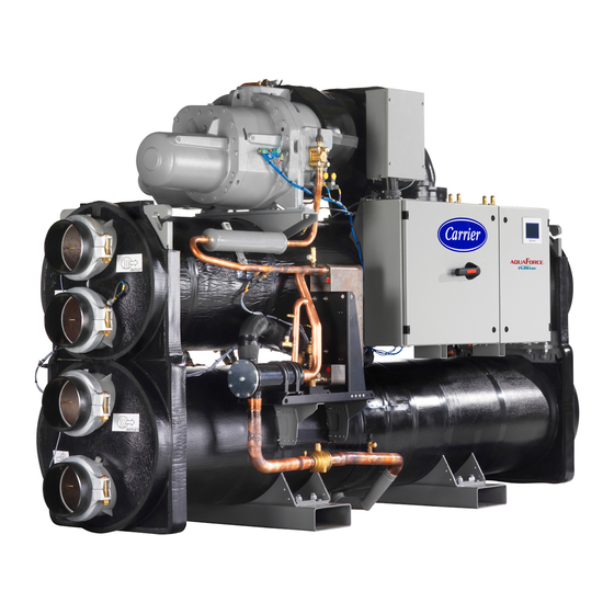
- Page 1 I N S T A L L A T I O N , O P E R A T I O N A N D M A I N T E N A N C E M A N U A L High temperature water-source heat pump AquaForce PUREtec with R1234ze(E)
-
Page 3: Table Of Contents
CONTENTS 1 - INTRODUCTION .................................... 5 1.1 - Installation safety considerations .............................. 5 1.2 - Equipment and components under pressure ..........................7 1.3 - Maintenance safety considerations ............................7 1.4 - Repair safety considerations ..............................8 2 - PRELIMINARY CHECKS ................................10 2.1 - Check equipment received .............................. - Page 4 CONTENTS 10 - OPTIONS AND ACCESSORIES ............................... 26 11 - STANDARD MAINTENANCE ..............................27 11.1 - Level 1 maintenance ................................27 11.2 - Level 2 maintenance ................................27 11.3 - Level 3 (or higher) maintenance ............................27 11.4 - Tightening of the electrical connections ..........................28 11.5 - Tightening torques for the main bolts and screws ........................
-
Page 5: Introduction
These devices, as well as the discharge Carrier also provides additional guidelines for the safe use piping, must not impair operation or lead to a pressure drop that of R1234ze(E) refrigerant that should be added to the is higher than 10% of the set pressure. - Page 6 Under certain conditions they permit connection of several valves to the same discharge pipe. Carrier recommends using flexible hose to connect the relief valves to discharge pipe. Special care shall be taken so that coupling to discharge pipe is not creating mechanical stress on relief valve connection.
-
Page 7: Equipment And Components Under Pressure
1 - INTRODUCTION Ensure good ventilation, as accumulation of refrigerant in an Equip the engineers that work on the unit as follows: enclosed space can displace oxygen and cause asphyxiation or Operations explosions. Personal protection Maintenance, Welding or equipment (PPE) Handling Inhalation of high concentrations of vapour is harmful and may service... -
Page 8: Repair Safety Considerations
An example of test procedure without removing the pressure switch for any purpose. Oxygen gas reacts violently with oil, grease, is given in Section 11.9 of this manual. Consult Carrier Service for and other common substances. Nitrogen should be used to this type of test. - Page 9 1 - INTRODUCTION Avoid contact with liquid refrigerant on the skin or splashing it into Do not attempt to repair or recondition any safety devices the eyes. Use safety goggles. Wash any spills from the skin with when corrosion or build-up of foreign material (rust, dirt, soap and water.
-
Page 10: Preliminary Checks
2 - PRELIMINARY CHECKS 2.1 - Check equipment received CAUTION: Lift and set down the unit with great care. Tilting and jarring can damage the unit and impair unit operation. ■ Inspect the unit for damage or missing parts. If damage is detected, or if shipment is incomplete, immediately file a claim ... -
Page 11: Dimensions, Clearances
3 - DIMENSIONS, CLEARANCES 3.1 - 61XWHLZE/61XWH-ZE/61XWHHZE 03-05-07 See detail B See detail A See detail C 1200 Inlet air 61XWHLZE/61XWH-ZE/61XWHHZE connection Model Dimensions in mm 1594 723 981 2724 982 141,3 141,3 2600 1745 891 1041 3059 1039 168,3 168,3 2900 1968 1007 1079 3290 1170 219,1 219,1 3100 Legend 1000... -
Page 12: 61Xwhlze/61Xwh-Ze 10-14-15-17; 61Xwhhze 10-15
3 - DIMENSIONS, CLEARANCES 3.2 - 61XWHLZE/61XWH-ZE 10-14-15-17; 61XWHHZE 10-15 See detail A See detail B See detail C 61XWHLZE/61XWH-ZE Model Dimensions in mm 2002 1432 1124 4730 1124 219,1 219,1 4500 1785 2070 1432 1148 4730 1237 219,1 219,1 4500 2305 1458 1399 4790 1264 219,1 219,1 4500 2305 1458 1399 4790 1264 219,1 219,1 4500 Inlet air... -
Page 13: Physical And Electrical Data
4 - PHYSICAL AND ELECTRICAL DATA 4.1 - Physical data 61XWHLZE/61XWH-ZE/61XWHHZE Model Sound levels - standard unit Sound power level dB(A) Sound pressure level at 1m dB(A) Sound levels - option 257 Sound power level dB(A) Sound pressure level at 1m dB(A) Dimensions - 61XWHLZE/61XWH-ZE Length... -
Page 14: Electrical Data
4 - PHYSICAL AND ELECTRICAL DATA 4.2 - Electrical data 61XWHLZE / 61XWH-ZE Model Power circuit Nom. power supply V-ph-Hz 400-3-50 Voltage range 360-440 Control circuit 24 V via the built-in transformer Maximum start-up current - Standard unit Circuit A 1210 1828 1919... -
Page 15: Short-Circuit Stability Current For All Units
Carrier representative. the installation for prevention of the formation of explosive atmospheres... -
Page 16: Electrical Connection
Wire sizing is the responsibility of the installer, and depends on which will invalidate the Carrier warranty. If the phase imbalance exceeds 2% for voltage, or 10% for current, contact the characteristics and regulations applicable to each installation your local electricity supplier at once and ensure that the unit site. -
Page 17: Power Cable Entry
5 - ELECTRICAL CONNECTION Table of minimum and maximum connectable wire sections. Calculation favourable case: Calculation unfavourable case: Connectable Perforated horizontal conduit Closed conduit wire section (standardised routing No. 15) (standardised routing No. 41) XLPE insulated cable PVC insulated cable, if possible 61XWHLZE / 61XWH-ZE Section Section... -
Page 18: Application Data
6 - APPLICATION DATA 6.1 - Operating limits 6.3 - Maximum chilled water flow The maximum chilled water flow is limited by the permitted 6.1.1 - 61XWHLZE / 61XWH-ZE units pressure drop in the evaporator. It is provided in the table in chapter 7.6. -
Page 19: Variable Flow Evaporator
6 - APPLICATION DATA 6.7 - Variable flow evaporator Variable evaporator flow can be used. The controlled flow rate must be higher than the minimum flow given in the table of permissible flow rates and must not vary by more than 10% per minute. If the flow rate changes more rapidly, the system should contain a minimum of 6.5 liters of water per kW instead of 3.25 l/kW. 6.8 - System minimum water volume Whichever the system, the water loop minimum volume is given by the formula:... -
Page 20: Evaporator Pressure Drop Curves
6 - APPLICATION DATA 6.9 - Evaporator pressure drop curves 6.10 - Condenser pressure drop curves Units with two evaporator passes (standard): Units with two condenser passes (standard): 3 4 5/6 100 110 120 90 100 110 120 Water flow rate, l/s Water flow rate, l/s Legend Legend Model 3... -
Page 21: Water Connections
Nominal diameter a gas, and that they belong to class 2, as defined in directive 97/23/ Actual outside diameter mm 141,3 168,3 219,1 219,1 219,1 219,1 219,1 Condenser Carrier recommendations on heat exchange fluids: Standard unit • No NH ammonium ions in the water, they are very Nominal diameter detrimental for copper. This is one of the most important Actual outside diameter mm 141,3 168,3 219,1 219,1 219,1 219,1 219,1 factors for the operating life of copper piping. -
Page 22: Flow Control
In this case two additional and the chilled water pump interlock must be connected. sensors must be added on the common piping. Failure to follow this instruction will void the Carrier guarantee. All parameters, required for the master/slave function must be configured using the MST_SLV menu. -
Page 23: Operating Mode For Heat Pump Units 61Xwh
Repair and modification that The 06T screw compressor is approved for use with the following necessitate permanent assembly (soldering, welding, lubricant: CARRIER MATERIAL SPEC PP 47-38. expanding etc.) must be made using the correct procedures and by qualified operators. 9.1.4 - Oil supply solenoid valve •... -
Page 24: Detection Of The Air Pressurization Of The Electrical Cabinet
This is also the case for the products originally supplied by Carrier. For maintenance instruction on expansion valves please refer to paragraph 12.8. - Page 25 9 - MAJOR SYSTEM COMPONENTS AND OPERATION DATA 9.8.2 - Function description and reset: Diagram below describes the description of operation: refer to the machine documentation to obtain the detailed wiring diagram HPD SP_F HPD SP_FA (115Vac) Normal Start-stop Normal Logic Start-stop Normal Start-stop Compressor A_C board...
-
Page 26: Options And Accessories
10 - OPTIONS AND ACCESSORIES Use for Options No. Description Advantages 61XWH range Star / delta start 25A Star / Delta start on each compressor Reduced start-up current 3-5, 10 Unit equipped with supplementary water outlet temperature sensor kit to be field-installed allowing Optimised operation of two units connected in Master/slave operation 3-17 master/slave operation of two units connected in... -
Page 27: Standard Maintenance
HVAC unit Simple procedure can be carried out by the user: null and void, and the manufacturer, Carrier France, will no • Visual inspection for oil traces (sign of a refrigerant leak) longer be held responsible •... -
Page 28: Tightening Of The Electrical Connections
11 - STANDARD MAINTENANCE 11.4 - Tightening of the electrical connections 11.4.1 - Tightening torques for the main electrical connections Screw type Designation in the unit Torque value, N•m Screw on bus bar, customer connection L1/L2/L3 L1/L2/L3 Soldered screw PE, customer connection (M12) Screw on fused disconnect inlet zones Fused disconnect 1034061/M10, customer connection L1/L2/L3 L1/L2/L3... -
Page 29: Tightening Torques For The Main Bolts And Screws
Maintenance work must be carried out by a trained person fully drop across the check valve and solenoid valve is approximately qualified to work on these units. Please contact your Carrier 0.4 bar, which should be subtracted from the two oil pressure Service representative for information. -
Page 30: High Pressure Safety Loop Periodic Test
11 - STANDARD MAINTENANCE 11.9 - High pressure safety loop periodic test 11.9.2 - Complete safety loop test The purpose of this periodic test is to verify the proper functioning In order to verify the full integrity of the safety loop, the following and setting of the high-pressure safety loop of a refrigerant circuit. -
Page 31: Final Shutdown
12 - FINAL SHUTDOWN 12.1 - Shutting down Separate the units from their energy sources, allow them to cool then drain them completely. 12.2 - Recommendations for disassembly Use the original lifting equipment. Sort the components according to their material for recycling or disposal, in accordance with regulations in force. Check whether any part of the unit can be recycled for another purpose. -
Page 32: Start-Up Checklist For 61Xwh Unit (Use For Job File)
13 - START-UP CHECKLIST FOR 61XWH UNIT (USE FOR JOB FILE) Preliminary information Job name: ........................................ Location: ........................................Installing contractor: ....................................Distributor: ....................................... Unit Model: ....................Compressors Circuit A Circuit B Model number.................. Model number ................Serial number .................. Serial number ................Motor number .................. - Page 33 WARNING: Operation of the unit with an improper supply voltage or excessive phase imbalance constitutes abuse which will invalidate the Carrier warranty. If the phase imbalance exceeds 2% for voltage, or 10% for current, contact your local electricity supplier at once and ensure that the unit is not switched on until corrective measures have been taken.
- Page 36 Order No.: 10190, 11.2020. Supersedes order No.: 10190, 06.2018. Manufactured by: Carrier SCS, Montluel, France. Manufacturer reserves the right to change any product specifications without notice. Printed in the European Union.
Need help?
Do you have a question about the AquaForce PUREtec 61XWHLZE 03 and is the answer not in the manual?
Questions and answers