Advertisement
Quick Links
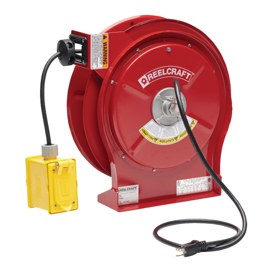
Operating Instructions
Series L 5000 Spring Driven Cord Reels
L 5550 123 3
L 5550 123 3B
L 5550 123 3A
L 5550 123 7
Dimensions - Size Index
Safety Precautions
Personal injury and/or equipment damage may
result if proper safety precautions are not
observed.
• Ensure that only a qualified electrician
installs/services this equipment.
• Ensure that power supply voltage does not
exceed maximum voltage rating of reel.
• Ensure that reel is properly installed before
connecting to power supply.
• All cord reels with flying leads must be hard
wired to ensure proper function.
Installation Instructions
2
1
3
Reelcraft Industries, Inc. • 2842 E Business Hwy 30, Columbia City, IN 46725
Ph: 800-444-3134 / 260-248-8188 • Fax: 800-444-4587 / 260-248-2605
Customer Service: 855-634-9109 • reelcraft@reelcraft.com • www.reelcraft.com
L 5550 123 7A
L 5550 123 X
L 5550 123 7Q
L 5550 124 X
A
17 5/8"
B
16 3/4"
C
9 3/4"
D
2 1/2"
E
10 1/2"
F
2 1/8"
• Ensure that all electrical power is removed
from reel before servicing.
• A high-tension spring assembly is
contained within the reel. Exercise extreme
caution.
• Check for frayed and/or broken wires before
each use. Pull electrical cord from reel by
grasping the electrical cord itself, not the
work device.
• If an electrical malfunction should occur,
remove power from reel immediately.
Mounting
CAUTION: Unless reel was specified differently
when ordering, maximum installation height
is 16 feet. Do not exceed this distance. Ensure
that only a qualified electrician installs/services
this equipment. Installation of GFCI cord reels
should be performed by a qualified and licensed
professional in accordance with building codes
and applicable NEC standards.
1. Unpack and inspect reel for damage. Turn
by hand to check for smooth operation.
Check for completeness.
IMPORTANT
Read this manual carefully before installing,
operating or servicing this equipment.
Electrical Information
Voltage
AMPS
125
13
125
15
600
16
125
20
125
30
• Ensure that reel, electrical cord, and
equipment being serviced are properly
grounded. Use an ohmmeter to check
ground continuity.
• If reel ceases to unwind or rewind, remove
power immediately. Do not pull or jerk on
electrical cord!
• Treat and respect the reel as any other piece
of machinery, observing all common safety
practices.
2. Configure reel for top, side or bottom-
wind (bottom-wind for constant tension
reels only) electrical cord dispensing by
removing bolts (1), securing guide arm
bracket (2). Determine new guide arm
location and remove corresponding bolts.
Position guide arm bracket to reel and
replace bolts.
3. Position reel on floor, wall, or ceiling.
Secure into place, using four (customer
supplied) screws or bolts (3).
Frequency
60 HZ Single Phase
60 HZ Single Phase
60 HZ Single Phase
60 HZ Single Phase
60 HZ Single Phase
Form# 565-291 Rev: 9/2023
Advertisement

Subscribe to Our Youtube Channel
Related Manuals for ReelCraft L 5000 Series


Summary of Contents for ReelCraft L 5000 Series
- Page 1 Check for completeness. Form# 565-291 Rev: 9/2023 Reelcraft Industries, Inc. • 2842 E Business Hwy 30, Columbia City, IN 46725 Ph: 800-444-3134 / 260-248-8188 • Fax: 800-444-4587 / 260-248-2605 Customer Service: 855-634-9109 • reelcraft@reelcraft.com • www.reelcraft.com...
- Page 2 2. Screw elbow (1) into reel. assembly. Refer any other discrepancies only to an authorized service 3. Connect input wires (3) and collector ring wires (4) together using person or directly to Reelcraft. splicing connectors (5). WARNING: The following procedure directs the technician to take 4.
- Page 3 Reelcraft. Failure to do so can result in personal 2. Remove nuts holding brush holder (10) to reel. Relocate cable injury and/or equipment damage and may void the warranty (refer to clamp (8) temporarily and remove brush holder (10).
- Page 4 Series L 5000 Cord Reels 8 11 Page 4 www.reelcraft.com...
- Page 5 29 Cover 261723 261723 261723 261723 30 Inlet Cord Assembly Plug 260630 602002 602002 260630 31 Outlet Box/Cord Assembly 602332-50 32 Outlet Cord Assembly Receptacle 600282 602386 602451-50 33 Flying Leads 34 Bumper Assembly 1-HR1004 1-HR1004-A 1-HR1004-A 1-HR1004 www.reelcraft.com Page 5...
- Page 6 29 Cover 261723 261723 261723 261723 30 Inlet Cord Assembly Plug 602002 602002 262307 262328 31 Outlet Box/Cord Assembly 602333-50 602813-50 32 Outlet Cord Assembly Receptacle 33 Flying Leads 602353-50 602475-50 34 Bumper Assembly 1-HR1004 1-HR1004 1-HR1004 1-HR1004 Page 6 www.reelcraft.com...
Need help?
Do you have a question about the L 5000 Series and is the answer not in the manual?
Questions and answers