Page 1
For the standard servicing method, refer to the FILE NO. A03-009, A04-008 and A05-004-1. New models compliance with EMC: IEC61000-3-12
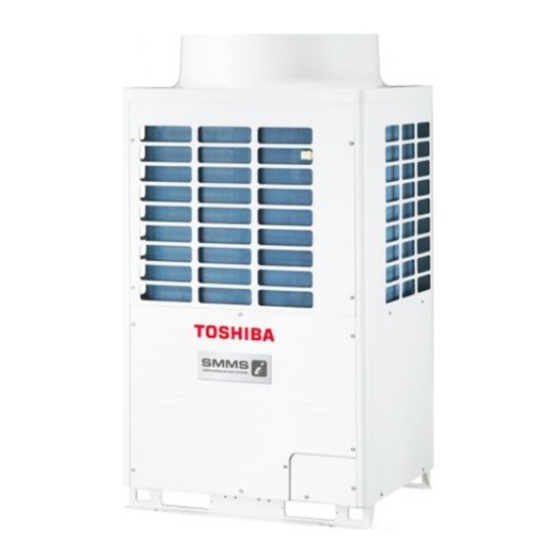
 < Outdoor Unit > Heat Pump Model MMY-MAP0501HT8-E, MMY-MAP0601HT8-E, MMY-MAP0801HT8-E, MMY-MAP1001HT8-E, MMY-MAP1201HT8-E Cooling Only Model MMY-MAP0501T8-E, MMY-MAP0601T8-E, MMY-MAP0801T8-E, MMY-MAP1001T8-E, MMY-MAP1201T8-E...
CONTENTS 1. DIFFERENT POINTS OF THE MAIN PARTS ..........3 2. WIRING DIAGRAM ..................4 2-1. Outdoor Unit ......................4 3. TROUBLESHOOTING (Passive Filter Circuit) ........... 7 4. CONFIGURATION OF CONTROL CIRCUIT ..........9 4-1. Outdoor Unit ......................9 5. RUNNING CHANGE .................. 10 5-1.
1. DIFFERENT POINTS OF THE MAIN PARTS This model is added with the passive filter to the fan driving circuit of the existing model and then Type name is changed. (“-E” is added to the end of the Type name.) 1.
3. TROUBLESHOOTING (Passive Filter Circuit) n Diagnosis procedure for each check code <SMMS Series (A03-009, A04-008) > Check code name Check code name Cause of operation 1. Incorrect model setup in service for I/F P .C. board [L29] / [CF] IPDU quantity error 2.
Page 8
<SHRM Series (A05-004-1) > Check code name Check code name Cause of operation 1. Incorrect model setup in service for I/F P .C. board [L29] / [CF] IPDU quantity error 2. Communication error between IPDU, fan IPDU and I/F (d07 / AI-NET) 3.
4. CONFIGURATION OF CONTROL CIRCUIT 4-1. Outdoor Unit Power P.C. board for fan (MCC-1439) Judgement +12V terminal 1 – 5 +7V terminal 2 – 5 Communication between fan IPDU DC330V output (For Comp. IPDU) CN500 Communication DC330V output for fan IPDU betweenI/F and (Judgemant : DC 180–370V) fan IPDU...
5. RUNNING CHANGE 5-1. Remote Controller Switch Name Wired remote controller Wired remote controller CODE No. CODE No. SET DATA DATA SETTING TEST UNIT No. UNIT No. ð SETTING TEST R.C. R.C. TEMP . ON / OFF Appearance TIMER SET MODE TIME SWING/FIX...
5-4. Refrigerant Recovery When Replacing the Compressor n How to operate the system during repairing of the defective outdoor unit MMY-MAP0501HT8(-E), MMY-MAP0601HT8(-E), MMY-MAP0801HT8(-E), MMY-MAP1001HT8(-E), MMY-MAP1201HT8(-E) <Work procedure> 1. Follow to the abovementioned “13-1. Refrigerant Recovery in the Troubled Outdoor Unit”. 2.
5-5. Replacing Method of Parts <SMMS Series (A03-009, A04-008) > Part to be Work procedure Remarks exchanged Pressure SV3C SV3C SV3A SV3A SV3D SV3D SV3B SV3B sensor positions of Rear side Rear side 2-way valve coil Liquid tank Liquid tank SV3E SV3E Accumulator...
Page 17
Part to be Work procedure Remarks exchanged Temperature <Rear side of air conditioner> sensor positions and identification Rear side TK sensor (White) Accumulator TK1 sensor (Black) TK1 sensor (Black) Accumulator side Accumulator side (Rear side) (Rear side) TK2 sensor (Blue) TK2 sensor (Blue) Front side Front side...
Page 18
<SHRM Series (A05-004-1) > Part to be Work procedure Remarks exchanged Pressure sensor SV3C SV3C SV3A SV3A SV3D SV3D SV3B SV3B positions of 2-way valve coil Rear side Rear side Liquid tank Liquid tank SV3E SV3E Accumulator Accumulator Oil separator Oil separator SV41 SV41...
Page 19
Part to be Work procedure Remarks exchanged <Rear side of air conditioner> Temperature sensor positions TK3 sensor(White) TK1 sensor(Black) and identification Accumulator side (Front side) Rear side Accumulator Liquid tank Oil separator TK4 sensor (Green) TK2 sensor (Blue) (Rear side) Attachment/ This air conditioner has been designed so that vibration has been reduced to a minium by detachment of...
5-6. P.C. Board Exchange Procedures (Outdoor Unit) n How to Check Fan Power Supply P.C. Board and Fan IPDU The fan power supply P .C. board supplies DC power. It supplies DC280V for the fan IPDU, and DC12V and DC7V for the control power supply respectively. If the control power is not supplied, a communication error (Error code [E31]) is out.
6. DETACHMENTS (Passive Filter Circuit) Part name Work procedure Remarks Passive filter <Fig.1> CAUTION CN507 of “Power supply P.C. board for FAN” Wear protective clothing on your hands as other components may cause injury etc. WARNING Never open the cabinet while 5 minutes after turn off the power supply.
Page 22
Part name Work procedure Remarks Passive filter 9) Remove rear panel. (Screw M5 × 10 , 7pcs) <Fig.6> (Continued) 10) Remove the screw which is fixing the passive filter box. (Screw M4 × 10 , 2 pcs) <Fig.6> 11) Take out the passive filter box outside. <Fig.7> 12) Remove The lid of the passive filter box.
Page 23
Part name Work procedure Remarks <Assembly> Passive filter (Continued) <Fig.11> Assembling by contrary procedure of above 10) → 12). Is connector of the power supply P .C. board for fan connected? Connector No.: CN501, CN502, CN503, CN505, CN506, CN507 Power supply P .C. board A’SSY for Fan: MCC-1439 Is the passive filter connector connected? <Fig.