Panasonic EYFMH1WC Operating Instructions Manual
Cordless electronic mechanical pulse wrench
Hide thumbs
Also See for EYFMH1WC:
- Operating instructions manual (352 pages) ,
- Operating instructions manual (10 pages)
Table of Contents
Advertisement
Quick Links
Operating Instructions
Instructions d'utilisation
Manual de instrucciones
Battery pack is not included.
Le bloc batterie n'est pas inclus.
Batería no incluida.
IMPORTANT
Read and follow the safety and operating instructions before using this product.
Do not use the wireless function outside the country where you purchased the product.
Doing so may violate the local laws and regulations.
WICHTIG
Lesen Sie vor der Verwendung dieses Produktes die Sicherheitsanweisungen und die
Bedienungsanleitung und befolgen Sie sie.
Verwenden Sie die Drahtlos-Funktion nicht außerhalb des Landes, in dem Sie das
Produkt erworben haben.
Dies könnte gegen örtliche Gesetze und Vorschriften verstoßen.
IMPORTANT
Lisez et suivez les instructions d'utilisation et de sécurité avant d'utiliser ce produit.
N'utilisez pas la fonction sans fil en dehors du pays où vous avez acheté le produit.
Cela pourrait enfreindre les lois et réglementations locales.
IMPORTANTE
Leggere e seguire le istruzioni per l'uso e di sicurezza prima di utilizzare questo prodotto.
Non utilizzare la funzione wireless al di fuori del Paese in cui è stato acquistato il
prodotto. Ciò potrebbe violare le leggi e i regolamenti locali.
IMPORTANTE
Lea y siga las instrucciones de seguridad y operación antes de usar este aparato.
No utilice la función inalámbrica fuera del país donde adquirió el
producto. Hacerlo podría infringir las leyes y normativas locales.
Cordless
Electronic Mechanical Pulse Wrench
Sans fil
Clé à impulsion mécanique électronique
Inalámbrica
Llave de impulso mecánica electrónica
Model No.: EYFMH1WC
Battery Operated Tool
Outil fonctionnant sur batterie
Herramienta con pilas
EYFMH2WC
EYFMH1WP
EYFMH2WP
Advertisement
Table of Contents

Related Manuals for Panasonic EYFMH1WC


Summary of Contents for Panasonic EYFMH1WC
- Page 1 Herramienta con pilas Cordless Electronic Mechanical Pulse Wrench Sans fil Clé à impulsion mécanique électronique Inalámbrica Llave de impulso mecánica electrónica Model No.: EYFMH1WC EYFMH2WC EYFMH1WP EYFMH2WP Battery pack is not included. Le bloc batterie n’est pas inclus. Batería no incluida.
-
Page 2: Table Of Contents
Table of Contents 1. BEFORE USE 1.1 GETTING STARTED .........................3 1.1.1 OBTAINING THE TOOL MANAGER SOFTWARE ............3 1.1.2 OBTAINING THE OPERATING INSTRUCTIONS ............4 1.2 SAFETY PRECAUTIONS ......................5 1.2.1 ADDITIONAL SAFETY RULES ..................5 1.2.2 INTENDED USE ......................7 1.3 FUNCTIONAL DESCRIPTION ....................8 1.4 EXTRA-COST OPTIONS ......................10 1.5 WIRING DIAGRAM ........................11 1.6 CHARGING ..........................12... -
Page 3: Getting Started
Access the following download site and download the installer of the Tool Manager software. (For how to install the Tool Manager software, Refer to 2.2.1 The Tool Manager software download site. https://www.panasonic-powertools.eu/en/construction/documents.htm • Please use the latest version. - 3 -... -
Page 4: Obtaining The Operating Instructions
1.1 GETTING STARTED 1.1.2 OBTAINING THE OPERATING INSTRUCTIONS Access the following download site and download the Operating Instructions of EYFMH1WC or EYFMH2WC. For full version Operating Instructions, please refer to the web site. https://www.panasonic-powertools.eu/en/construction/documents.htm - 4 -... - Page 5 1.2 SAFETY PRECAUTIONS 1.2.1 GENERAL POWER TOOL SAFETY WARNINGS WARNING Read all safety warnings, instructions, illustrations and specifications provided with this power tool. Failure to follow all instructions listed below may result in electric shock, fire and/or serious injury. The term “power tool” in the warnings refers to your mains-operated (corded) power tool or battery-operated (cordless) power tool.
- Page 6 1.2 SAFETY PRECAUTIONS 1.2.1 GENERAL POWER TOOL SAFETY WARNINGS 3) Personal Safety a) Stay alert, watch what you are doing and use common sense when operating a power tool. Do not use a power tool while you are tired or under the influence of drugs, alcohol or medication.
- Page 7 1.2 SAFETY PRECAUTIONS 1.2.1 GENERAL POWER TOOL SAFETY WARNINGS d) Store idle power tools out of the reach of children and do not allow persons unfamiliar with the power tool or these instructions to operate the power tool. Power tools are dangerous in the hands of untrained users. e) Maintain power tools and accessories.
- Page 8 1.2 SAFETY PRECAUTIONS 1.2.1 GENERAL POWER TOOL SAFETY WARNINGS f) Do not expose a battery pack or tool to fire or excessive temperature. Exposure to fire or temperature above 130 °C (266 °F) may cause explosion. g) Follow all charging instructions and do not charge the battery pack or tool outside the temperature range specified in the instructions.
-
Page 9: Safety Precautions
1.2 SAFETY PRECAUTIONS 1.2.1 ADDITIONAL SAFETY RULES 1) Wear ear protectors when using the tool for extended periods. Prolonged exposure to high intensity noise can cause hearing loss. 2) Be aware that this tool is always in an operating condition, since it does not have to be plugged into an electrical outlet. - Page 10 1.2 SAFETY PRECAUTIONS 1.2.1 ADDITIONAL SAFETY RULES WARNING • Do not use other than the Panasonic battery packs that are designed for use with this rechargeable tool. • Panasonic is not responsible for any damage or accident caused by the use of recycled or counterfeit battery pack.
-
Page 11: Intended Use
1.2 SAFETY PRECAUTIONS 1.2.2 INTENDED USE This tool is a Cordless Mechanical Pulse Wrench and can be used to tighten bolts, nuts, and screws. Additionally, it provides a torque control function that automatically stops tool operation when a preset load is reached to deliver consistent tightening torque. IMPROPER USE The use of the tool other than INTENDED USE is dangerous and must be avoided. -
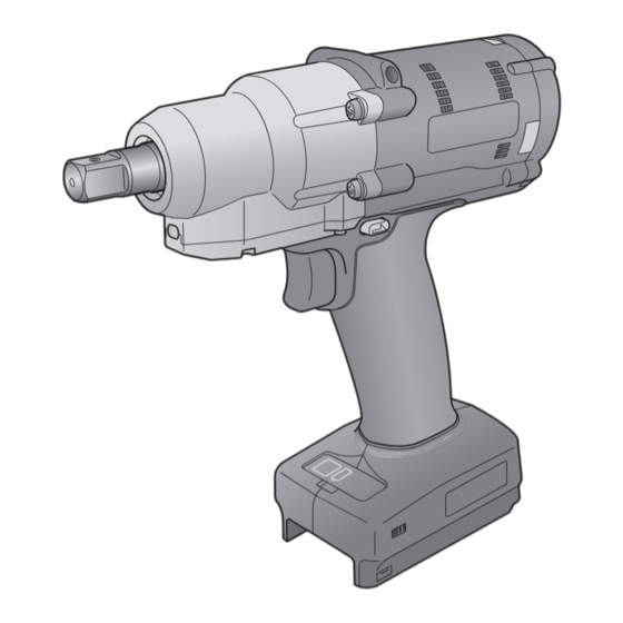
Page 12: Functional Description
1.3 FUNCTIONAL DESCRIPTION Tool Square drive (retainer ring and pin) Square drive (pin-detent type) Pin-detent Retainer ring (EYFMH1WC / EYFMH2WC) (EYFMH1WP / EYFMH2WP) Sensor block Note • The QR code on the lower Tightening part of the sensor block confirmation... - Page 13 1.3 FUNCTIONAL DESCRIPTION Control Panel Refer to 2.1.5 Display Battery indication lamp LED light ON/OFF button Accessory USB cable 1 m EYFMH1XL701W - 13 -...
-
Page 14: Extra-Cost Options
• The tool hanger is for a balancer only. If any strong force or shock is applied, it may break to cause the tool to fall. Note • Please purchase the battery pack, EYFB41 or EYFB43. • Please purchase the retainer ring (C-ring), EZ7552K0187 (EYFMH1WC, EYFMH2WC). - 14 -... -
Page 15: Wiring Diagram
1.5 WIRING DIAGRAM The tool can be used by being Programming software connected to external devices as • Tool Manager (Model No. : EYFSW102) shown in the connection diagram [Compatible OS] below. • Windows10 Home/Windows10 Pro/Windows10 Enterprise [Features] • View work results, Manage work result files •... -
Page 16: Charging
1.6 CHARGING Before Charging You can charge a sliding lithium-ion battery pack. (Charging EYFB41 or EYFB43) Install a battery charger in a place with a temperature of 5 °C to 40 °C, and charge the battery pack that is close to the temperature of the charging place. If the battery pack temperature is 5 °C or below or significantly different from the charging place temperature, there may be a lack of charging. - Page 17 1.6 CHARGING How to Charge Plug the charger into the AC outlet. Note • Sparks may be produced when the plug is inserted into the AC power supply, but this is not a problem in terms of safety. Insert the battery pack firmly into the charger. ①...
- Page 18 1.6 CHARGING Consult an authorized dealer if the charging lamp (green) does not turn off. If a fully charged battery pack is inserted into the charger again, the charging lamp lights up. After several minutes, the charging lamp in green color will turn off. Remove the battery pack while the battery pack release button is held up.
- Page 19 1.6 CHARGING █ Federal Communication Commission Interference Statement This equipment has been tested and found to comply with the limits for a Class B digital device, pursuant to Part 15 of the FCC Rules. These limits are designed to provide reasonable protection against harmful interference in a residential installation.
-
Page 20: Tool Setups Before Use
1.7 TOOL SETUPS BEFORE USE Hold the forward/reverse lever Center in the center to keep it in a Switch lock position switch lock position. Rubber ring Attach a socket. ① Remove a rubber ring and a pin from Groove the socket. ②... -
Page 21: Operation
2.1 BASIC OPERATION 2.1.1 OPERATION MODE OF THE TOOL The tool operates in one of the following modes. The mode in which it is used now is shown on the display of the control panel. Display Display Mode name Mode details This is a mode in which the tool operates according to the Stand Alone configured parameters registered in its inside. -
Page 22: Torque Control Function
2.1 BASIC OPERATION 2.1.2 TORQUE CONTROL FUNCTION The tightening torque for the work target is calculated by the torque sensor of the tool. When the calculated torque value reaches the preset target value, the tool is supposed to stop (shut off) automatically. (For how to set the Shut-Off Torque, Refer to 2.2.8 WARNING... -
Page 23: How To Use
2.1 BASIC OPERATION 2.1.3 HOW TO USE Choose forward or reverse with the forward/reverse lever, and turn on the trigger switch. • Trigger switch pull-in operation may delay the startup of rotation for a moment, which is not a failure. •... - Page 24 2.1 BASIC OPERATION 2.1.3 HOW TO USE See the tightening confirmation lamp display to check whether torque control has functioned. For the tightening confirmation lamp display, Refer to 2.1.4 Note • At reverse work, the tightening Tightening confirmation lamps do not light up. confirmation •...
-
Page 25: Tightening Confirmation Lamp And Communication Lamp
2.1 BASIC OPERATION 2.1.4 TIGHTENING CONFIRMATION LAMP AND COMMUNICATION LAMP You can check the tightening result and the communication status by seeing the LED lamps on the tool. Tightening confirmation lamp Tightening Confirmation Lamp Display Lamp display Meaning of display Details Lit for 2 s The tightening work reached the set shut-... - Page 26 2.1 BASIC OPERATION 2.1.4 TIGHTENING CONFIRMATION LAMP AND COMMUNICATION LAMP You can check the tightening result and the communication status by seeing the LED lamps on the tool. Communication lamp Communication Lamp Display Lamp display Meaning of display Details When the communication lamp is blinking fast, some communications have taken place Blinking fast inside the tool or between the tool and external...
-
Page 27: Control Panel Functions
2.1 BASIC OPERATION 2.1.5 CONTROL PANEL FUNCTIONS Power is in an OFF state when all the lamps on the control panel have gone out. Pull the trigger switch once to activate the tool before operating it. In the following cases, power will be in an OFF state to cut battery drain, and the LED light and all the displays will go out. - Page 28 2.1 BASIC OPERATION 2.1.5 CONTROL PANEL FUNCTIONS How to Read the Battery Indication Lamp • You can check the remaining battery level. • Use the remaining battery level for reference, because it varies somewhat with the ambient temperature, battery properties, etc. Battery indication lamp Status display Remaining battery level...
-
Page 29: Using The Tool Manager Software
2.2 USING THE TOOL MANAGER SOFTWARE 2.2.1 INSTALLING AND UPDATING THE TOOL MANAGER SOFTWARE Before using the tool, install the Tool Manager software in your PC or tablet by following the procedure below. Preparation: Prepare a PC or tablet with the supported OS installed. (For the supported OS, Refer to 3.2 Installation... - Page 30 2.2 USING THE TOOL MANAGER SOFTWARE 2.2.1 INSTALLING AND UPDATING THE TOOL MANAGER SOFTWARE When the screen to confirm installation is displayed, select [Next] (⑥). When the Windows dialog is displayed asking whether to allow the application to make a change to your device, select [Yes]. Installation of the Tool Manager software starts.
-
Page 31: Uninstalling The Tool Manager Software
2.2 USING THE TOOL MANAGER SOFTWARE 2.2.2 UNINSTALLING THE TOOL MANAGER SOFTWARE You can uninstall the Tool Manager software by performing the standard Windows procedure for uninstalling the application. Uninstalling the Tool Manager software does not clear the data of history log, configured parameters, and option settings, which will be taken over if the Tool Manager software is reinstalled. -
Page 32: Repairing The Tool Manager Software
2.2 USING THE TOOL MANAGER SOFTWARE 2.2.3 REPAIRING THE TOOL MANAGER SOFTWARE You can repair the Tool Manager software via its installer. Try this if the Tool Manager software will not start. On your PC or tablet with the Tool Manager software installed, start the installer of the Tool Manager software as described in 2.2.1. -
Page 33: Starting/Exiting The Tool Manager Software
2.2 USING THE TOOL MANAGER SOFTWARE 2.2.4 STARTING/EXITING THE TOOL MANAGER SOFTWARE You can start and exit the Tool Manager software by following the procedure below. Start the Tool Manager Software To start the Tool Manager software, select Tool Manager on the desktop or from the Windows start menu. -
Page 34: Connecting/Disconnecting The Tool
2.2 USING THE TOOL MANAGER SOFTWARE 2.2.5 CONNECTING/DISCONNECTING THE TOOL The tool and your PC or tablet on which the Tool Manager software is installed can be used by connecting them with a USB cable. Preparation: Attach a charged battery pack to the tool. Start the Tool Manager software installed on your PC or tablet. - Page 35 2.2 USING THE TOOL MANAGER SOFTWARE 2.2.5 CONNECTING/DISCONNECTING THE TOOL Connect the Tool If power to the tool is not on, pull the trigger switch of the tool to turn on the power. Connect the tool to your PC or tablet with a USB cable. CAUTION •...
- Page 36 2.2 USING THE TOOL MANAGER SOFTWARE 2.2.5 CONNECTING/DISCONNECTING THE TOOL If a tool ’ s internal clock is different from a clock of your PC or tablet in time by 10 seconds or more, the dialog will ask whether to correct the time of the tool ’ s internal clock to that of the clock of your PC or tablet.
- Page 37 2.2 USING THE TOOL MANAGER SOFTWARE 2.2.5 CONNECTING/DISCONNECTING THE TOOL Disconnect the Tool Unplug the USB cable from the tool or the connected PC or tablet. CAUTION • If the communication lamp (blue) on the tool is blinking fast (0.2 s cycle), this means that data is being communicated.
-
Page 38: Screen Layout Of The Tool Manager Software
2.2 USING THE TOOL MANAGER SOFTWARE 2.2.6 SCREEN LAYOUT OF THE TOOL MANAGER SOFTWARE ● ③ ● ① ● ④ ● ⑤ ● ② ● ⑦ ● ⑥ Name Overview ① Opens the menus and windows of file, option, and help. Menu bar ②... - Page 39 2.2 USING THE TOOL MANAGER SOFTWARE 2.2.6 SCREEN LAYOUT OF THE TOOL MANAGER SOFTWARE ● ⑨ ● ⑧ Name Overview This is a list for selecting a configured parameter file to edit. ⑧ Parameter list It can be selected from the data saved in the tool being connected or the Tool Manager software.
-
Page 40: Managing The Tool From The Tool List
2.2 USING THE TOOL MANAGER SOFTWARE 2.2.7 MANAGING THE TOOL FROM THE TOOL LIST A tool to operate with the Tool Manager software is selected from the tool list. The tool list displays the tools being connected with the Tool Manager software or the tools that have been connected before. - Page 41 2.2 USING THE TOOL MANAGER SOFTWARE 2.2.7 MANAGING THE TOOL FROM THE TOOL LIST Hide the Tool The tool in a disconnected state can be hidden from the tool list. (The data of the hidden tool remains in the Tool Manager software, and it can be recalled with [Open Tool].) Select a disconnected tool on the tool list, and click [Hide].
- Page 42 2.2 USING THE TOOL MANAGER SOFTWARE 2.2.7 MANAGING THE TOOL FROM THE TOOL LIST Recall the Tool The hidden tool can be recalled with [Open Tool]. Click [Open Tool] to display the dialog to open tools. Select a serial number of the tool to display from the [Hidden tools] list (①), click [Open] (②), and move it to the [Tools to display] list (③).
- Page 43 2.2 USING THE TOOL MANAGER SOFTWARE 2.2.7 MANAGING THE TOOL FROM THE TOOL LIST Delete the Tool The tool in a disconnected state can be deleted from the tool list. The history log data of the deleted tool is completely erased from the Tool Manager software.
-
Page 44: Configuring Parameters Of The Tool
2.2 USING THE TOOL MANAGER SOFTWARE 2.2.8 CONFIGURING PARAMETERS OF THE TOOL This tool can be used by configuring parameters that specify the operation. (1) How to Use Parameters █ Stand Alone Mode The tool runs according to the parameters registered in its internal storage. At configuration At work USB cable...
Need help?
Do you have a question about the EYFMH1WC and is the answer not in the manual?
Questions and answers