Advertisement
TABLE OF CONTENTS
1 Warning -------------------------------------------------------------- 2
2 Specifications ----------------------------------------------------- 2
3 Troubleshooting Guide ----------------------------------------- 3
4 Disassembly and Assembly Instructions ---------------- 6
5 Appendix -----------------------------------------------------------11
6 Exploded View and Replacement Parts List -----------12
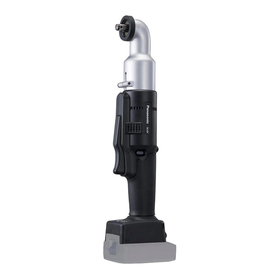
Cordless Right Angle Impact
Model No.
Europe
PAGE
©
Unauthorized copying and distribution is a violation
of law.
Order Number PTD1710E39CE
EYFME1C
Panasonic corporation 2017. All rights reserved.
PAGE
Advertisement

Related Manuals for Panasonic EYFME1C


Summary of Contents for Panasonic EYFME1C
-
Page 1: Table Of Contents
2 Specifications ----------------------------------------------------- 2 3 Troubleshooting Guide ----------------------------------------- 3 4 Disassembly and Assembly Instructions ---------------- 6 5 Appendix -----------------------------------------------------------11 6 Exploded View and Replacement Parts List -----------12 © Panasonic corporation 2017. All rights reserved. Unauthorized copying and distribution is a violation of law. -
Page 2: Warning
1 Warning Caution: • Pb free solder has a higher melting point that standard solder; Typically the melting point is 50 - 70°F (30 - 40°C) higher. Please use a soldering iron with temperature control and adjust it to 750 ± 20°F (400 ± 10°C). In case of using high temperature solder- ing iron, please be careful not to heat too long. -
Page 3: Troubleshooting Guide
3 Troubleshooting Guide 3.1. Troubleshooting Guide... - Page 5 3.2. Trial Operation (after checking Troubleshooting Guide). 3.2.1. Assembly • Confirm if there is no gap between housing A and B by pinching lead wires. • There is no dust or deformation on battery terminals. 3.2.2. Operation • Check whether the tool speed increases continuously as the trigger is gradually engaged. •...
-
Page 6: Disassembly And Assembly Instructions
4 Disassembly and Assembly Instructions * To reduce the risk of injury, always remove battery pack before removing/installing the tool. * To assemble the tool, start with 4-10 and proceed to 4-1. 4.1. How to remove the gear case assembly 4.2. - Page 7 4.5. Precautions when removing the module assembly...
- Page 8 4.6. Checking and setting the module assembly’s DIP switches 4.7. How to remove the anvil, anvil bushing, thrust plate and slider 4.8. How to remove the driving shaft assembly and motor mounting plate assembly...
- Page 9 4.9. How to remove the driving shaft assembly 4.10. Caution in replacing the switch (WEYFGA1NK207)
- Page 10 4.11. Wiring and Assembly Points...
-
Page 11: Appendix
5 Appendix Error Display In the event of a tool or battery pack malfunction, the control panel will display an error message. Please check the tool or battery pack as described in the following chart before having them serviced. The battery indication lamp •... -
Page 12: Exploded View And Replacement Parts List
6 Exploded View and Replacement Parts List Model No. : EYFME1C Exploded View... - Page 13 Model No. : EYFME1C Parts List Ref. Change Safety Part No. Part Name & Description Q'ty Remarks WEYFME1CK677 HEX UPSET BOLT (5PCS/PK) WEYFME1CS427 GEAR CASE ASSEMBLY WEYFME1CS457 DRIVING SHAFT COVER ASSEMBLY WEYFME1CL437 SQ BEVEL GEAR ASSEMBLY WEYFME1CL137 BEVEL PINION ASSEMBLY...
Need help?
Do you have a question about the EYFME1C and is the answer not in the manual?
Questions and answers