
Related Manuals for Denjoy iFinder


Summary of Contents for Denjoy iFinder
- Page 1 Rev. 09/24/20 VER SMS-DY20140715RPIF-EN USER MANUAL iFinder Apex Locator *The unit must be installed by a qualified engineer. *Only for use by dental professionals. *Read this operation manual carefully before installation or operation.
-
Page 2: Table Of Contents
Rev. 09/24/20 VER SMS-DY20140715RPIF-EN Contents SECTION 1: GENERAL INTRODUCTION SECTION 2: MAIN TECHNICAL INDEX SECTION 3: COMPONENTS SECTION 4: FUNCTIONS SECTION 5: OPERATION SECTION 6: SAFETY PRECAUTIONS SECTION 7: MANTENANCE & SERVICE SECTION 8: TOUBLESHOOTING GUIDE SECTION 9: ENVIRONMENTAL REQUIREMENTS REMARKS: The pictures here are for reference only. - Page 3 Rev. 09/24/20 VER SMS-DY20140715RPIF-EN Please contact sales distributor directly from whom you have purchased this device for user’s record and further after-sale service.
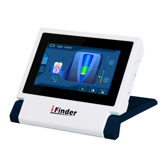
- Page 4 Please keep this user’s manual for future reference. Apex locator iFinder is our latest model with TFT touch-screen used for determining the position of apex of root canal with the up-to-date technology multi-frequency operation system.
- Page 5 Rev. 09/24/20 VER SMS-DY20140715RPIF-EN Caution: Consult accompanying documents Date of manufacture. Manufacturer Specifies serial number Type BF applied part Refer to instruction manual / booklet Sterilizable up to the temperature specified at most The device should not be used after the end of the shown or the day DISPOSAL: Do not dispose this product as unsorted municipal waste.
-
Page 6: Section 2: Main Technical Index
Rev. 09/24/20 VER SMS-DY20140715RPIF-EN SECTION 2: MAIN TECHNICAL INDEX 1. Classification: Internally powered equipment 2. AC Adapter Input voltage: 220V /50Hz Output voltage:5V 1A Battery:3.7V 2200mAh 3. Display mode: 4.3 “ TFT 800*480 color screen 4. Dimension: 132*120*31mm 5. Weight: about 500g 6. - Page 7 Rev. 09/24/20 VER SMS-DY20140715RPIF-EN 1. Power on/off 2, SD slot 3. Probe wire socket 4. AC adapter socket 5. Mode Switch key 6. Up key 7. Down key 8. Save key Accessories: A. Probe wire 1 pc B. Autoclaved File holder 2 pcs C.
- Page 8 Rev. 09/24/20 VER SMS-DY20140715RPIF-EN 2. Main interface 3. Self-calibration interface 4. Up key for length adjuster of apical constriction 5. Down key for length adjuster of apical constriction 6. Brightness control key 7. Sound adjuster 8. Save key 9. Length between top of file and the apex of root canal 10.
- Page 9 Rev. 09/24/20 VER SMS-DY20140715RPIF-EN On the Main Interface, user can adjust 4 level brightness of the screen by touching the brightness control key. After adjustment, touch the enter key, shown in Figure 2, it means set successfully. Please note, no operation for 10 seconds, it will automatically return to Main Interface.
- Page 10 Rev. 09/24/20 VER SMS-DY20140715RPIF-EN Figure 3 4.4 Up/Down key for length adjuster of apical constriction On the Main Interface, user can touch up/down key for length adjuster of apical constriction to adjust the apical line. 4.5 Battery sign The symbol lies on the top left corner of the screen. Full charge Battery is charging.
- Page 11 Rev. 09/24/20 VER SMS-DY20140715RPIF-EN MARK 1. Calibration key for control part MARK 2. Calibration key for accessories (probe wire, file holder, hooks) 1) Self-calibration steps: Firstly, control part Secondly, accessories 2) The device needs self-calibration for following reasons: * The apex locating result is not accurate. * While the accessories are aging after a long time use.
- Page 12 Rev. 09/24/20 VER SMS-DY20140715RPIF-EN Figure 4 Figure 5 4.7. Calibration key for accessories (probe wire, file holder and hooks) On the self-calibration interface, insert the probe wire into matching socket, connect calibrator test instrument with file holder and electrode hook, touch Calibration key for accessories (MARK 2), if as...
- Page 13 Rev. 09/24/20 VER SMS-DY20140715RPIF-EN shown in Figure 6, it means self-calibrating successfully showing “√” on the LCD. Figure 6 If as shown in Figure 7, it means self-calibrating unsuccessfully “X” on the LCD. Figure 7...
-
Page 14: Section 5: Operation
Rev. 09/24/20 VER SMS-DY20140715RPIF-EN SECTION 5: OPERATION Touch-screen key and traditional button control are both available! When first used, insert the calibrator into the device to observe whether the screen display is 0.3 upper and lower two grids, otherwise the machine is defective,and the plug of the cord should be inserted completely into the device. -
Page 15: Section 6: Safety Precautions
Rev. 09/24/20 VER SMS-DY20140715RPIF-EN 5.5. Hang the stainless hook up at any side of the patient’s mouth, insert the file into the teeth, when the endodontic file reaches the position which the number indicated in the color screen is AP. Then please fasten the file with the rubber positioning ring on the reference point of the tooth crest. - Page 16 Rev. 09/24/20 VER SMS-DY20140715RPIF-EN using the cardiac pacemaker, or there is an electronic operation, please don't put the machine around. The cardiac pacemaker sufferer, viz. the serious cardiac pulse abnormality sufferer, is forbidden to use this machine. 6.3. Please put in the battery before use. Make sure that the power of the battery is in sufficient supply to guarantee the correct measurement result.
- Page 17 Rev. 09/24/20 VER SMS-DY20140715RPIF-EN For ACCURATE MARESUREMENT: ● Make sure that stainless hook entirely contact patient’s mouth mucosa. ● Check all connections ● Make sure that when the device is switched on, the device can complete self-checking procedure automatically and successfully. When following situations appear, please use paper point part to make root canal dry to increase accuracy of measurement.
-
Page 18: Section 7: Mantenance & Service
Rev. 09/24/20 VER SMS-DY20140715RPIF-EN SECTION 7: MANTENANCE & SERVICE 7.1. MANTENANCE The device is maintained free of charge and doesn't require any routine maintenance within warranty period. The device cannot be repaired. Do not modify and disassemble the device. This device described below has been fully inspected and confronts to the current products specification. -
Page 19: Section 8: Toubleshooting Guide
Rev. 09/24/20 VER SMS-DY20140715RPIF-EN When the surface of main body is polluted, please rub the surface with dry soft cloth ONLY. REMARKS: Any liquid lotion like ethanol, banana oil and light oil are not allowed. PROBE WIRE CLEANING INSTRUCTION Please wipe the probe wire with the soft cloth stained with ethanol and reuse it after it is completely dry. -
Page 20: Section 9: Environmental Requirements
Rev. 09/24/20 VER SMS-DY20140715RPIF-EN b. The file has not reached the point less than 2.0 at which the machine will give an alarm. Question: NO changes or incorrect reading on the LCD screen Answer: a. Do not clip the file with the holder firstly and switch on the device secondly. - Page 21 Table 1 Guidance and manufacturer’s declaration - electromagnetic emissions The [iFinder] is intended for use in the electromagnetic environment specified below. The customer or the user of the [iFinder] should assure that it is used in such an environment Emissions test...
- Page 22 Rev. 09/24/20 VER SMS-DY20140715RPIF-EN are not likely to cause any interference in nearby electronic equipment. RF emissions Class [B] The [iFinder] is suitable for use in CISPR 11 all establishments other than domestic, and may be used in Harmonic Class A...
- Page 23 Rev. 09/24/20 VER SMS-DY20140715RPIF-EN Guidance and manufacturer’s declaration - electromagnetic emissions The [iFinder] is intended for use in the electromagnetic environment specified below. The customer or the user of the [iFinder] should assure that it is used in such an environment Immunity Test...
- Page 24 0.5 cycle for 0.5 cycle environment. If the user variations of the [iFinder] requires power supply 40% U 40% U continued operation input lines (60% dip in (60% dip in...
- Page 25 Table 3 Guidance and manufacturer’s declaration - electromagnetic emissions The [iFinder] is intended for use in the electromagnetic environment specified below. The customer or the user of the [iFinder] should assure that it is used in such an environment Immunity...
- Page 26 Rev. 09/24/20 VER SMS-DY20140715RPIF-EN 3 V/m 3 V/m Radiated 80MHz 2.5GHz 61000-4-3 where p is the maximum output power rating of the transmitter in watts (W) according to the transmitter manufacturer and d is the recommended separation distance in meters (m) Field strengths from fixed RF transmitters, as determined by an electromagnetic site survey,...
- Page 27 To assess the electromagnetic environment due to fixed RF transmitters, an electromagnetic site survey should be considered. If the measured field strength in the location in which the [iFinder] is used exceeds the applicable RF compliance level above, the [iFinder] should be observed to verify normal operation.
- Page 28 Rev. 09/24/20 VER SMS-DY20140715RPIF-EN Rated maximum Separation distance according to frequency of output power of transmitter transmitter 150 kHz to 80 80MHz to 800MHz 800MHz to 2.5GHz d=1.2 d=1.2 d=2.3 0,01 0.12 0.23 0.38 0.73 For transmitters rated at a maximum output power not listed above, the recommended separation distance d in metres (m) can be estimated using the equation applicable to the frequency of the transmitter, where P is the maximum output power rating of the transmitter in watts (W) according to the...
- Page 29 Rev. 09/24/20 VER SMS-DY20140715RPIF-EN WARRANTY REGISTRATION FORM Item Name: Model Name: Serial No.: Date of Purchase: Name: Address:...
- Page 30 Rev. 09/24/20 VER SMS-DY20140715RPIF-EN...
Need help?
Do you have a question about the iFinder and is the answer not in the manual?
Questions and answers