
Related Manuals for SOMFY animeo Solo 2 zone


Summary of Contents for SOMFY animeo Solo 2 zone
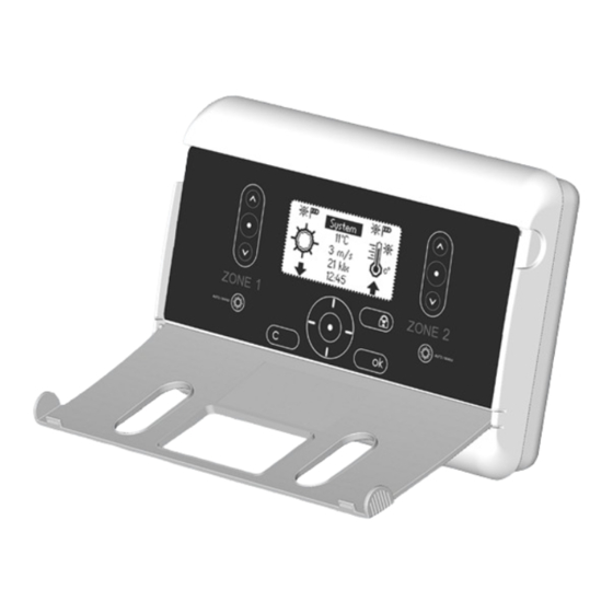
- Page 1 ® animeo Solo 2 zone Operating manual 1860144 ©2007-2023, SOMFY ACTIVITÉS SA, Société Anonyme. ALL RIGHTS RESERVED. REF. 5053700C – 2023/11/06...
-
Page 2: Table Of Contents
Table of content Welcome ......... 3 Settings .........22 Icons used in this manual ......3 Test and Demo mode ........22 Glossary used in this manual ......3 Test mode ..........22 Demo mode ........22 Status .............22 Getting started ......... 4 Sensors ..........22 What is an automatic solar protection system? .. -
Page 3: Welcome
Welcome Congratulations for purchasing Somfy animeo Solo, one of the most modern, efficient and easiest way to control solar protection and rolling shutters on the market. Before installation, please read and follow these instructions carefully. An incorrect installation could lead to serious injury. The product must be installed by a qualified electrician. -
Page 4: Getting Started
For more information about motor relays and other accessories see www.somfy.com or contact nearest dealer. * H If there is only one AC motor to be connected, it can be connected without a motor relay. -
Page 5: How To Use And Navigate In Animeo Solo
How to use and navigate in animeo Solo The animeo Solo is very easy to use. This chapter explains all possibilities in detail. We recommend you to read this part through at least once to better understand the whole concept in order to explore many of the nice features and possibilities. -
Page 6: Explanation Of Flashing Function Icons
Explanation of flashing function icons Below are some examples of function statuses when the icon is flashing: Info “Nothing” Sun icon Sun on delay is counting. Solar protection will soon be ordered out. Sun icon “Nothing” Sun off delay is counting. Solar protection will soon be ordered in. -
Page 8: Basic Setup (First Start Up)
Basic setup (first start up) The animeo Solo system is prepared to be able to operate automatically from the first start up (after the short start up wizard has been set). The standard functions are already enabled. Default settings are used on parameters such as thresholds and delays. Adapt your system to your needs If you feel that the system is not corresponding to your needs of life then you can make adaptations on the default settings. -
Page 9: System Functions
System functions Introduction In this chapter we go through all functions in detail. But first some information that is good to know to better understand the system in general. H In the system menu you can not access the functions “Lock” (both via unit and via exter- nal switch) or the manual commands (both via unit and via external switch). -
Page 10: Manual And Automatic Mode
Manual and Automatic mode In automatic mode all functions can get active. In manual mode functions 9-12 in the table can not get active, meaning that no down commands will be given automatically. Manual commands (see page 14-15) can be performed in both manual and automatic mode. Lock zone- via control unit About: When this function is active the selected zone’s solar protection will be blocked in up position. -
Page 11: Alarm
Check the cable between the system and the sensor so that it is not damaged or broken. Check that the sensor is not damaged and that it can rotate. If the error still remains please contact your nearest Somfy dealer. H This function is active in both manual and automatic mode. This function is always ena- bled and can not be disabled. - Page 12 / Wind Use function... Use function... Threshold... Delay... Sensor allocation... The first parameters in the wind function menu H If it’s both very windy and sunny at the same time, the solar protection will of course be blocked in up position in order to secure that no damage of the solar protection will occur. This means that the wind function has higher priority than the sun function.
-
Page 13: Rain
Recommended MAX wind speed values for different solar protection Type Wind speed On delay Off delay Km/h Façade awning / screen External Venetian blind Folding arm awning H For exact values please contact the solar protection supplier. Rain About: The Rain function is used to protect the solar protection from rain and snow. Doing so will prolong the life span of the solar protection, especially if they are made of fabric. -
Page 14: Frost
Frost About: The Frost function is used to protect the solar protection from getting stuck when frost. Doing so will prolong the life span of the solar protection. Enable this function for each zone where you have external solar protection by selecting Yes in the “Use function”... -
Page 15: Manual Command - Via External Switch
Active: By pressing on the up, stop, down push buttons (see page 5) you activate this func- tion and can command the solar protection, per zone, to any wanted position. When you com- mand the solar protection down and if you press a second time on the down button whilst the solar protection is running, a tilt action will be performed (see page 20 for more info). -
Page 16: Get Heat
Adapt the function: Go to the “Set timer” parameters and change the time span (start and stop time) as you want it per weekday. Last check that the direction parameter is set either up or down according to your needs. Use this function to position your solar protection independent of present weather con- ditions. -
Page 17: Preserve Heat
and vice versa. Lastly, if you find that the function is still active even though there haven’t been any sun for a while then decrease the Off delay and vice versa. Sensor allocation: Sun sensor allocation is used to set which sun sensor the function should listen to. - Page 18 / Preserve heat Use function... Set Timer... Delay... Temperature threshold... the Preserve heat function menu The timer span is normally set during non working hours to ensure, when the building is occu- pied, visual contact with the outside through the windows. This function is mainly used during nights.
-
Page 19: Sun
About: The Sun function is used to command the end products to specific position when there is sun. Using this function helps to avoids over heating and glaring situa- tions inside the building. Sun function can only get active in automatic mode. Enable this function for each zone by selecting Yes in the “use function”... -
Page 20: Motor - Running And Tilt Times
Sun parameters Function Range (Step) Per Zone Default Advanced Used Yes/No Threshold On 5-50klux 20klux Threshold Off 5-50klux 15klux On Delay 1-10min 2min Off Delay 5-60min 30min Allocation 1 or 2 common, 1/zone Motor – Running and Tilt times Here you set the desired down position of the solar protection (Running time) and slat angle if you are controlling a blind (Tilting time) for each zone. -
Page 21: Set Down Running Time
H The motors have a built-in limit setting that should be set by the installer of the solar protection. The limit settings avoids that the solar protection may get damaged if you set too long running times. Set Down running time Make sure that solar protection for the zone in question is fully up by commanding the zone up via the manual command button. -
Page 22: Settings
Running and Tilting time parameters Function Range Per Zone Default Expert Down 5-300s 180s 5-300s 180s Tilt 0-5s 1,0s Settings This chapter explains features that are not directly related to any function. Test and Demo mode When test or demo mode is activated it is shown at the bottom of the main menu. Test mode This feature is very efficient when testing an installation. -
Page 23: Error List
means how long the LCD screen backlight should be on after that no interaction has been done on the system. As soon as you press any button again the backlight will be lit up again. Error list In the Error list you can see the errors that the system has. The error messages can be good to start from in order to solve the problem. -
Page 24: External Inputs And Outputs
Stop is generated by a simultaneous up and down signal. This function is equal to the manual push buttons on the control unit (see page 14/15). The inputs are IB compatible meaning e.g. a Somfy Centralis switch can be used. Error output If an error would occur this potential free output will be activated (Low = Error). -
Page 25: Faq
- Check if there is an error indicated on the LCD screen or in the error list (see page 11). - Read the installation guide (ref. 5053517) for other important information. - Contact your supplier or www.somfy.com Tip when testing If you want to test a function, e.g. -
Page 26: Compatible Sensors & Switches
Rain Rain sensor (24 V, dry contact)* * = additional power supply needed Warranty Somfy leaves 5 years warranty on all products. Please check www.somfy.com for detailed information. Support Please contact your supplier or search for nearest support at www.somfy.com... - Page 28 SOMFY ACTIVITÉS SA 50 Avenue du Nouveau Monde 74300 Cluses France T +33 (0)4 50 96 70 00 F +33 (0)4 50 96 71 89 www.somfy.com www.somfy.com/projects...
Need help?
Do you have a question about the animeo Solo 2 zone and is the answer not in the manual?
Questions and answers