
Subscribe to Our Youtube Channel
Related Manuals for Iseki SSM72


Summary of Contents for Iseki SSM72
- Page 1 I S E K I M O W E R D E C K O p e r a t o r ’s & S e r v i c e M a n u a l MODELS: SSM72 SSM60 FOR TG6400,6370...
-
Page 2: Introduction
ISEKI MOWER DECK INTRODUCTION Thank you very much for purchasing an ISEKI mower deck. This manual provides the information necessary for operating and maintaining your mower deck safely and prop- erly. The contents are mainly composed of the following two items: SAFETY INSTRUCTION: Essential items which you should observe during operating the mower deck. - Page 3 SSM72 SSM60...
-
Page 4: Table Of Contents
INSTALLATION OF THE LINKAGE ON THE TRACTOR ............26 STORING OF THE MOWER DECK ......49 INSTALLATION OF THE MOWER DECK FOR SSM72 ............26 TROUBLESHOOTING ..........50 INSTALLATION OF THE MOWER DECK FOR SSM60 ............27 INSTALLATION OF THE JOINT COVER ..... 28 LINK ADJUSTMENT .......... -
Page 5: For Safe Operation
SSM72 SSM60 FOR SAFE OPERATION DANGER: Failure to observe the following safety instructions can result in serious injury or death. As the owner or operator of the tractor, you are responsible for pre- venting accidents or injuries. 1. HOW TO BE A SAFE OPERATOR 1.1. -
Page 6: Before Starting The Tractor
FOR SAFE OPERATION 1.9. Inspect the tractor periodically. If not, this may not only shorten the tractor’s service life but also make safe and efficient operation impossible. 1.10. Never use the tractor out of normal usage even if it is not mentioned at this manual. 2. - Page 7 SSM72 SSM60 2.12. Use only attachments and accessories ap- proved by the manufacturer and install and operate them as directed. 2.13. When your tractor is equipped with an imple- ment other than a standard mower deck, such as a collector, a cabin, etc., never fail to ask your dealers about machine balance.
-
Page 8: Operation Of The Tractor
FOR SAFE OPERATION 3. OPERATION OF THE TRACTOR 3.1. When the tractor is running, stay away from the discharge hole, the cutting unit(s), and all moving parts. 3.2. During operation, never allow anyone, especially children, and animals to be in the vicinity of the tractor. - Page 9 SSM72 SSM60 3.15. Never rest a foot on the brake pedal. If so, the brakes disc wear rapidly, which may lead to serious accidents. 3.16. Travelling set with the cruise lever should be restricted only to operations in specious, flat...
- Page 10 FOR SAFE OPERATION 3.25. When driving over a levee, stop the mower blades, lift up the mower deck, and move the tractor straight to the levee and make it climb over slowly. Avoid climbing over a levee too high, or the tractor may fall sideways or turn over. 3.26.
-
Page 11: Operation On A Slope
SSM72 SSM60 4. OPERATION ON A SLOPE DANGER: Slopes are a major factor re- lated to accidents with tractors, resulting in severe injuries. We cannot recomend the tractor with mower deck be oparated on a slope. All slopes require extra caution;... -
Page 12: Mounting And Dismounting Of The Mower Drive Shaft
FOR SAFE OPERATION 4.5. Never perform mowing operation on wet grass. 4.6. Be sure to shift the 4WD lever to the 4WD position. 4.7. Never use the cruise control during mowing operation. 4.8. Choose a low gear to prevent the need to stop or shift gears on a slope. -
Page 13: Inspection And Maintenance
SSM72 SSM60 6. INSPECTION AND MAINTENANCE 6.1. Never start the engine in a closed place. Exhaust fumes contain poisonous carbon monoxide, so sufficient ventilation should be provided when starting the engine indoors. 6.2. Be sure to wear safety glasses and gloves when servicing the tractor. - Page 14 Dam- SSM72 8655-306-003-10 8655 C aged or worn parts should be replaced with ISEKI genuine spare parts. Unauthorized parts SSM60 8654-306-006-10 8654 C may cause breakdown of the tractor, accidents, and ISEKI warranty to expire.
-
Page 15: Safety Labels
SSM72 SSM60 SAFETY LABELS The following labels are stuck on the mower. You should of course read the safety instructions in the manual. But never fail to read the labels on the machine as well. Their respective code numbers are also mentioned below, so order replacements from your dealer if any of them are lost or damaged. -
Page 16: Position Of The Safety Labels
FOR SAFE OPERATION POSITION OF THE SAFETY LABELS Pay attention to the safety labels on the mower deck, and observe the instructions they give to avoid physical injuries. SSM72-TG6400E4 2-TG6400E4 SSM60-TG6400E4 0-TG6400E4 FIG. 1-4... -
Page 17: Maintenance Of The Safety Labels
SSM72 SSM60 MAINTENANCE OF THE SAFETY LABELS - The labels should always be clearly seen, that is, nothing should obscure them. - When they have become dirty, wash them with soap water and wipe with a soft cloth. - When some of them are torn or lost, order new labels from your dealers. -
Page 18: General Information
Each mower is identified by means of model and se- rial numbers. To ensure prompt, efficient service when ordering parts or requesting repairs from authorized ISEKI Dealer, record these numbers in the spaces provided. Machine Model Number: Machine Serial Number:... -
Page 19: Specifications
SSM72 SSM60 SPECIFICATIONS Model SSM72-TG6400E4 SSM60-TG6400E4 Suitable Machine TG6400 / TG6370 Type Rotary Mower Discharge Type Side Discharge Cutting Width 1,830 (72) 1,524 (60) mm (inch) Number of Blades Dimension 1,134 (44.6) 1,011 (39.8) Overall Length mm (inch) 2,285 (90.0) 1,928 (75.9) -
Page 20: Name Of Major Components
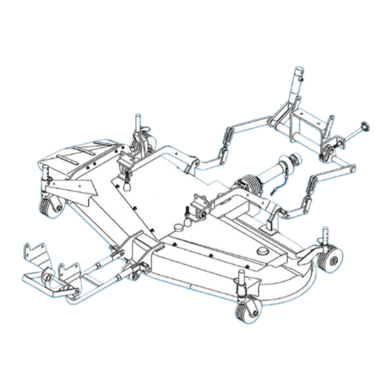
NAME OF MAJOR COMPONENTS NAME OF MAJOR COMPONENTS SSM72 FIG. 4-1 MOWER DECK UNIVERSAL JOINT DISCHARGE COVER STEP/LH STEP/RH BELT COVER/LH BELT COVER/RH JOINT COVER BELT (10) TENSION ARM (11) ROLLER (12) FRONT GAUGE WHEEL (13) REAR GAUGE WHEEL (14) BLADE... - Page 21 SSM72 SSM60 SSM60 FIG. 4-2 MOWER DECK UNIVERSAL JOINT DISCHARGE COVER BELT COVER/LH BELT COVER/RH JOINT COVER BELT TENSION ARM ROLLER (10) FRONT GAUGE WHEEL (11) REAR GAUGE WHEEL (12) BLADE...
-
Page 22: Assembling Instruction
Bolts should be tightened up according with the standard torque. INSTALLATION OF PACKING PARTS TO TRACTOR a. Take out all parts from box, then confirm them with referring to the FIG. of packing parts list for SSM72. FIG. 5-1... - Page 23 SSM72 SSM60 b. Take out all parts from box, then confirm them with referring to the FIG. of packing parts list for SSM60. FIG. 5-2 PARTS CODE PARTS NAME PARTS CODE PARTS NAME DECK/MOWER/60/TGSET 3650-380-220-10 HOSE / HYDRO / 900 ASSY...
-
Page 24: Before Installation
ASSEMBLING INSTRUCTION BEFORE INSTALLATION b. Fix mid-bracket (LH) and mid-bracket (RH) to both left and right side of the chassis with bolts and - Place the tractor on level, hard ground. washers. - Stop the engine and draw the engine key before mounting or dismounting the drive shaft. - Page 25 SSM72 SSM60 d-1. Assemble the height adjust system as indicated on FIG.5-8. These parts are not assembled in packing condition as indicated on FIG.5-9. After assembling, make sure that the SHAFT / ADJUST COMP, 1 rotates smoothly and PIN, SPLIT/3X35, 5 is completely split.
- Page 26 ASSEMBLING INSTRUCTION d-2. Install rear linkage to bottom of the rear e. Fix cylinder to the cylinder bracket with pin and ring transmission. pin. FIG. 5-11 FIG. 5-14 f. Remove bolt of the port and install adapter to the port. Connect the hose with adapter. FIG.
-
Page 27: Installation Of The Linkage On The Tractor
SSM72 SSM60 g. Route the hose. FIG. 5-20 FIG. 5-17 b. Drive tractor forward and drive over mower deck as INSTALLATION OF THE LINKAGE ON THE TRACTOR shown in the following photos. a Install mid arm onto rear link with fork and pin. -
Page 28: Installation Of The Mower Deck For Ssm60
ASSEMBLING INSTRUCTION FIG. 5-25 FIG. 5-23 d. Turn the main switch to “ON” position and lift down the link to the lowest position. e. Connect mid-arm to mower deck. FIG. 5-24 FIG. 5-26 f. Connect front arm to mower deck. INSTALLATION OF THE MOWER DECK FOR SSM60 a. -
Page 29: Installation Of The Joint Cover
SSM72 SSM60 INSTALLATION OF THE JOINT COVER FIG. 5-28 FIG. 5-31 g. Hook front arm onto front bracket and fasten them h. Connect the drive shaft of mower deck with Mid- by turning the lever. At this operation, adjust the PTO shaft. -
Page 30: Link Adjustment
ASSEMBLING INSTRUCTION FIG. 5-34 FIG. 5-36 LINK ADJUSTMENT a. Start the engine and lift the link up to the highest position by the hydraulic control lever. Stop the en- gine and turn the rear gauge wheels frontward. b. Under this condition, adjust the length of rear link so that the clearance between ground and bottom of mower deck is 150mm. -
Page 31: Operation Of Pto
SSM72 SSM60 OPERATION OF PTO PTO SWITCH & PTO SELECTABLE SWITCH FIG. 6-1: PTO switch, 1, is used to engage and disen- gage the PTO clutch. To engage the PTO clutch, turn the PTO switch clock- wise with pushing down the knob. When engaged, the PTO indicator lamp in the indicator light array will illuminate. -
Page 32: Mid Pto Selector Lever
OPERATION OF PTO The pressure control valve operates when the PTO clutch begins to operate, enabling efficient engaging of the PTO with a minimum of shock. Setting PTO selectable switch, 2, facilitates optimum engagement of the PTO. HST Type Turn PTO selectable switch, 2, to right to engage rear and mid PTO more smoothly and slowly. -
Page 33: Mower Operation
Lost or damaged ones should be re- placed with new ISEKI’s genuine parts. Especially before starting the mower, be sure to inspect visually to see that the blade and blade tightening bolts are not worn, damaged or loose. -
Page 34: Height Adjustment System
MOWER OPERATION HEIGHT ADJUSTMENT SYSTEM STARTING MOWING OPERATION Height adjustment system is standardly equipped - Mow only in daylight. on this tractor. During the operation on soft ground, when the height adjustment system is used, it helps - Pay attention to the safety around the machine to to decrease the mark of mower gauge wheel on the avoid injury to bystanders or damage to property. -
Page 35: Stopping The Mower
SSM72 SSM60 e. HST type: EMERGENCY STOP - Shift the throttle lever to the high-speed position. Stop the tractor and mower immediately when any of the following abnormalities is encountered. - Disengage the parking pedal. - Abnormal noise - Depress the HST forward travel pedal gradually... -
Page 36: Efficient Mowing
MOWER OPERATION EFFICIENT MOWING - Be sure to mow at full throttle. - Choose an adequate traveling speed in accor- dance with the height of grass to be cut. - Low cutting height will lead to poor mowing ef- ficiency and rapid blade wear. - When the screens for the air-intake openings are clogged with dust, clean them at once. - Page 37 SSM72 SSM60 3) For mowing tall grass a. Mow grass twice. First, mow to prepare the grass height to make it low enough for the next finishing pass. Then fin- ish to a desired grass height. Shift the second traveling pass sideways by 20cm (8 inch.) or so, or travel perpendicular to the prec-...
-
Page 38: Inspection And Service Of Each Part
INSPECTION AND SERVICE OF EACH PART INSPECTION AND SERVICE OF EACH PART CAUTION: • When servicing the mower, place the tractor on level, hard ground. • Stop the engine and remove key from the starter switch. • Apply the parking brake securely. •... - Page 39 SSM72 SSM60 2) Replacement of oil IMPORTANT: Replace oil after the initial 50 hours of operation and then after every 200 hours of operation. a. Remove the mower blade which is attached to the shaft of the gear case referring to the instructions for the replacement of the mower blades.
-
Page 40: Inspection And Replacement Of The Drive Belt
Check the tension of each belt. Measure the length or inter-coil clearance of the tension spring. FIG. 8-2 A: Length B: Clearance SSM72 FIG. 8-3 A: 129 - 131 mm (5.1 - 5.2 inch.) B: 1 - 1.2 mm (0.04 - 0.05 inch.) SSM60 FIG. - Page 41 Loosen the tension rod. b. Disengage the belt from the pulleys and install a new one. NOTE: Use a belt specified by ISEKI. c. Adjust the spring tension with the tension rod as shown in “Inspection of the belt tension”.
-
Page 42: Inspection And Replacement Of The Blades
INSPECTION AND SERVICE OF EACH PART INSPECTION AND REPLACEMENT OF THE BLADES 1) Inspection of the blades CAUTION: Be sure to wear gloves when inspecting or replacing the blades to avoid injuring your hands. a. Raise the mower to its highest level. Inspect the blades for wear and deformation. - Page 43 Chock a blade by inserting a piece of wood between the blade and mower deck to prevent the blades from rotating. Loosen the bolt tightening blade. c. Replace old blades with new ones. NOTE: Insist on ISEKI genuine blades when replacing. MODEL PARTS CODE...
-
Page 44: Inspection Of Gauge Wheels
INSPECTION AND SERVICE OF EACH PART INSPECTION OF GAUGE WHEELS Gauge wheels are very important parts to set the grass-cutting height. When a wheel does not turn smoothly or is deformed, replace it with a new gauge wheel immediately. INSPECTION OF ROLLERS Make sure that all rollers turn smoothly. -
Page 45: Washing The Machine
SSM72 SSM60 WASHING THE MACHINE CAUTION: If you use high pressure washer, be sure to use in accordance with this manual and safety label of washer. In case of irregular use, it may cause personal injury and damage to the machine. -
Page 46: Lubrication And Greasing Points
LUBRICATION AND GREASING POINTS LUBRICATION AND GREASING POINTS The parts listed below should be lubricated periodically with the lubricants specified. SSM72 FIG. 9-1 Description Lubricant to be used Quantity Gear Box Gear Oil: SAE80 930-950 cc Inject until grease overflow from lip of up-... - Page 47 SSM72 SSM60 SSM60 FIG. 9-2 Description Lubricant to be used Quantity Gear Box Gear Oil: SAE80 930-950 cc Inject until grease overflow from lip of up- Center Metal Grease per oil seal Inject until grease overflow from lip of up-...
-
Page 48: Disassembly And Reassembly
DISASSEMBLY AND REASSEMBLY DISASSEMBLY AND REASSEMBLY - As for the detachment of the mower from the tractor. - Remove the belt covers and other necessary parts to check the belts and other components for wear, damage, inspect or service each part if required. GEAR BOX a. -
Page 49: Backlash Adjustment
SSM72 SSM60 BACKLASH ADJUSTMENT a. Prepare the special jig as shown to measure the backlash at R25 mm of the output shaft. b. Place reassembled gear box sideways and lock the input shaft in order to prevent the shaft from turning. -
Page 50: Storing Of The Mower Deck
Check the V-belt and loosen the adjustable tensioner. h. Remove all rust and touch up where paint has peeled off with touch-up paint supplied by ISEKI. i. Check each part for damage and repair or replace damaged ones for the next operation. -
Page 51: Troubleshooting
SSM72 SSM60 TROUBLESHOOTING Troubles Presumable causes Remedies • Drive belt is not installed properly • Check belt and correct • Blades are installed upside down • Re-install them correctly • Grass is too moist • Wait until grass becomes dry •... - Page 52 TROUBLESHOOTING Troubles Presumable causes Remedies • Broken or unbalanced blades • Replace them with new ones • Loose blade tightening nuts • Re-tighten them • Clogged inside of mower or • Clean foreign matter caught in a pulley • Excessive noise and vibration •...
- Page 53 SSM72 SSM60...
- Page 54 DECLARATION OF CONFORMITY ISEKI & CO., LTD. 3-14 Nishi-Nippori 5-Chome Arakawa-ku 116-8541 Tokyo Japan declare under our sole responsibility that the products described below. Generic denomination: Agricultural machine Function: Agricultural, forestry use and ground care TG6400 TG6370 SSM72 SSM60 to which this declaration relates are in conformity with the following directives:...
- Page 55 SSM72 SSM60 FOR TG6400,6370 Overseas Business Division 5-3-14, Nishi-Nippori, Arakawa-ku, Tokyo 116-8541, Japan Phone: (03) 5604-7658 Fax: (03) 5604-7703 Parts code : 1815-912-201-0-EN Publishing date : 22 July 2015 Printed in Japan...
Need help?
Do you have a question about the SSM72 and is the answer not in the manual?
Questions and answers