
Subscribe to Our Youtube Channel
Related Manuals for Iseki SSM48


Summary of Contents for Iseki SSM48
- Page 1 I S E K I M O W E R D E C K Operation & Servise Manual MODELS: SSM48 SRM48 SSM54 SMM54 SSM60...
-
Page 2: Introduction
INTRODUCTION Thank you very much for purchasing an ISEKI mower. This operator’s manual is intended to provide the information necessary for operating and maintaining your mower safely and properly. The contents are mainly composed of the following two items: Safety instructions:... -
Page 3: Table Of Contents
2) For TH4330, 4290, 4260 tractors ..................26 CHAPTER 5. INSTALLATION ON THE TM TRACTOR .............. 28 Ⅰ. SSM48 / SRM48 ........................28 5-1. Before installation ......................28 5-2. Installation of the bracket and cylinder on the tractor ............ 28 5-3. - Page 4 7-2. Cutting height adjustment ....................46 7-3. Starting mowing operation....................47 7-4. Stopping the mower ......................48 7-5. Emergency stop ........................ 48 7-6. Efficient mowing ........................ 48 1) Mowing plan and method ....................48 2) For preventing damage of turf ..................49 3) For mowing tall grass ......................
-
Page 5: Chapter 1. For Safe Operation
OPERATION & SERVICE MANUAL FOR MOWER DECK CHAPTER 1. FOR SAFE OPERATION Read this manual thoroughly and carefully Never step on the mower deck. before starting the lawn mower for the first time. Especially abide by the instruction for safe oper- Be sure to alert them by signaling before you ation. - Page 6 CHAPTER 1. FOR SAFE OPERATION Service the machine in a place sufficiently illu- minated in order to avoid unexpected accidents. The engine, muffler, radiator, etc. are very hot just after operation, so wait until those heated parts cool down sufficiently to avoid burns. Avoid high-pressure fluids.
-
Page 7: Safety Labels
1-2. Position of the safety labels Pay attention to the safety labels on the mower, and observe the instructions they give to avoid physical injuries. 1) For TM3240, 3200, 3160 tractors SSM48-TM3160E4 Fig.1-1... - Page 8 CHAPTER 1. FOR SAFE OPERATION (1) Danger label (4) Hot label Caution: Caution: Keep clear of the mower blades while the Keep clear the hot surface.(6) Maintenance engine is running. label (2) Belt label (5) PTO label Caution: Caution: Do not remove the safety covers while the Keep clear of the PTO shaft while the engine is engine is running.
- Page 9 OPERATION & SERVICE MANUAL FOR MOWER DECK SSM54-TM3240E4 / HE4 Fig.1-2 (1) Danger label (3) Discharge label Caution: Caution: Keep clear of the mower blades while the Keep a safe distance from the mower. engine is running. (2) Belt label (4) Hot label Caution: Caution:...
- Page 10 CHAPTER 1. FOR SAFE OPERATION SSM60-TM3240E4 / HE4 Fig.1-3 (5) PTO label Caution: Keep clear of the PTO shaft while the engine is running. (6) Maintenance label Caution: Shut off the engine and remove the starter key before perform...
- Page 11 OPERATION & SERVICE MANUAL FOR MOWER DECK SRM48-TM3160E4 Fig.1-4 SMM54-TM3240E4 / HE4 Fig.1-5...
- Page 12 CHAPTER 1. FOR SAFE OPERATION (1) Belt label (4) PTO label Caution: Caution: Do not remove the safety covers while the Keep clear of the PTO shaft while the engine is engine is running. running. (2) Hot label (5) Maintenance label Caution: Caution: Keep clear the hot surface.
-
Page 13: For Th4330, 4290, 4260 Tractors
OPERATION & SERVICE MANUAL FOR MOWER DECK 2) For TH4330, 4290, 4260 tractors SSM60-TH4330E4 Fig.1-6 (1) Belt label (2) Hot label Caution: Caution: Do not remove the safety covers while the Keep clear the hot surface engine is running. - Page 14 CHAPTER 1. FOR SAFE OPERATION (3) Danger label (6) Maintenance label Caution: Caution: Keep clear of the mower blades while the Shut off the engine and remove the starter key engine is running. before performing maintenance or repair work. (4) PTO label 1-3.
-
Page 15: Chapter 2. General Information
Mid-Mount Mower. Every effort has been to provide correct and concise information to you, the operator, as available at date of publication. Your ISEKI Dealer is available, should items in Caution: In some of the illustrations used in this this manual or details of your machine not be Operator Instruction Book, panels or guards understood. -
Page 16: Machine Identification
Each mower is identified by means of model and serial numbers. To ensure prompt, efficient service when order- ing parts or requesting repairs from authorized ISEKI Dealer, record these numbers in the spaces provided. Machine Model Number: Machine Serial Number:... - Page 17 OPERATION & SERVICE MANUAL FOR MOWER DECK The mower identification plate (1) is located on SRM48-TM3160E4 the right-hand side of the deck. SSM48-TM3160E4 Fig.2-5 Fig.2-2 SMM54-TM3240E4 / HE4 SSM54-TM3240E4 / HE4 Fig.2-6 Fig.2-3 SSM60-TH4330E4 SSM60-TM3240E4 / HE4 Fig.2-4 Fig.2-7...
- Page 18 CHAPTER 2. GENERAL INFORMATION...
-
Page 19: Chapter 3. Specifications
OPERATION & SERVICE MANUAL FOR MOWER DECK CHAPTER 3. SPECIFICATIONS SSM48-TM3160E4 Model SSM48-TM3160E4 Suitable Machine TM3160-F Type Rotary Mower Discharge Type Side Discharge Cutting Width 48" (1224) inch (mm) Number of Blades Dimension Overall Length 33.9 (862) inch (mm) Overall Width 60.0 (1523) - Page 20 CHAPTER 3. SPECIFICATIONS SSM54-TM3240E4 / HE4 Model SSM54-TM3240E4 SSM54-TM3240HE4 Suitable Machine TM3240-F TM3200-F TM3240-FH TM3200-FH Type Rotary Mower Discharge Type Side Discharge Cutting Width 54" (1369) inch (mm) Number of Blades Dimension Overall Length 36.6 (929) inch (mm) Overall Width 67.2 (1708) inch (mm) Overall Height...
- Page 21 OPERATION & SERVICE MANUAL FOR MOWER DECK SSM60-TM3240E4 / HE4 Model SSM60-TM3240E4 SSM60-TM3240HE4 Suitable Machine TM3240-F TM3200-F TM3240-FH TM3200-FH Type Rotary Mower Discharge Type Side Discharge Cutting Width 60" (1524) inch (mm) Number of Blades Dimension Overall Length 39.2 (995) inch (mm) Overall Width 74.5 (1893)
- Page 22 CHAPTER 3. SPECIFICATIONS SRM48-TM3160E4 Model SRM48-TM3160E4 Suitable Machine TM3160-F Type Rotary Mower Discharge Type Side Discharge Cutting Width 48" (1225) inch (mm) Number of Blades Dimension Overall Length 33.2 (842) inch (mm) Overall Width 50.1 (1272) inch (mm) Overall Height 10.8 (274) inch (mm) Weight (Mower Deck + Linkage)
- Page 23 OPERATION & SERVICE MANUAL FOR MOWER DECK SMM54-TM3240E4/HE4 Model SMM54-TM3240E4 SMM54-TM3240HE4 Suitable Machine TM3240-F TM3200-F TM3240-FH TM3200-FH Type Rotary Mower Discharge Type Side Discharge Cutting Width 54" (1369) inch (mm) Number of Blades Dimension Overall Length 38.7 (983) inch (mm) Overall Width 57.0 (1449) inch (mm)
- Page 24 CHAPTER 3. SPECIFICATIONS SSM60-TH4330E4 Model SSM60-TH4330E4 Suitable Machine TH4260-F/-FH TH4330-FH TH4290-F/-FH Type Rotary Mower Discharge Type Side Discharge Cutting Width 60" (1524) inch (mm) Number of Blades Dimension Overall Length 39.2 (995) inch (mm) Overall Width 74.5 (1893) inch (mm) Overall Height 14.3 (364) inch (mm)
-
Page 25: Chapter 4. Name Of Major Components
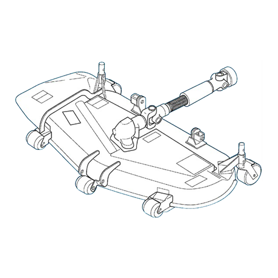
OPERATION & SERVICE MANUAL FOR MOWER DECK CHAPTER 4. NAME OF MAJOR COMPONENTS 1) For TM3240, 3200, 3160 tractors SSM48-TM3160E4 SSM54-TM3240E4 / HE4 Fig.4-1 Fig.4-2 Mower deck Mower deck Gear box Gear box Universal joint Universal joint Discharge cover Discharge cover... - Page 26 CHAPTER 4. NAME OF MAJOR COMPONENTS SSM60-TM3240E4 / HE4 SRM48-TM3160E4 Fig.4-3 Fig.4-4 Mower deck Mower deck Gear box Gear box Universal joint Universal joint Discharge cover Discharge cover Belt cover (LH) Belt cover (LH) Belt cover (RH) Belt cover (RH) Belt Belt Pulley...
-
Page 27: For Th4330, 4290, 4260 Tractors
OPERATION & SERVICE MANUAL FOR MOWER DECK 2) For TH4330, 4290, 4260 tractors SMM54-TM3240E4 / HE4 SSM60-TH4330E4 Fig.4-5 Fig.4-6 Mower deck Mower deck Gear box Universal joint Universal joint Discharge cover Belt cover (LH) Belt cover (LH) Belt cover (RH) Belt cover (RH) Belt Belt cover (Center) - Page 28 CHAPTER 4. NAME OF MAJOR COMPONENTS...
-
Page 29: Chapter 5. Installation On The Tm Tractor
OPERATION & SERVICE MANUAL FOR MOWER DECK CHAPTER 5. INSTALLATION ON THE TM TRACTOR Ⅰ Ⅰ . SSM48 / SRM48 5-1. Before installation - Place the tractor on level, hard ground. - Stop the engine and draw the engine key before mounting or dismounting the drive shaft. -
Page 30: Installation Of The Linkage On The Tractor
CHAPTER 5. INSTALLATION ON THE TM TRACTOR 5-3. Installation of the linkage on the tractor Fig.5-2 a. Install the MID-ARM (LH)(3) onto the MID- d. Connect the REAR LINK (5) and the CYLIN- BRACKET (LH) (9) by using the PIN (16X43) DER (6) by using the PIN (15X88) (14) and (11) and RING PIN (13). -
Page 31: Installation Of The Mower Deck
OPERATION & SERVICE MANUAL FOR MOWER DECK 5-4. Installation of the mower deck Fig.5-3 a. Before installing the mower deck Install the FRONT ARM (2) onto the mower Set the height of all gauge wheels to the lowest deck. position. g. -
Page 32: Installation Of The Drive Shaft
CHAPTER 5. INSTALLATION ON THE TM TRACTOR 5-5. Installation of the drive shaft Fig.5-4 a. The drive shaft should be mounted or dismount- ed always at the tractor side. b. Install the drive shaft of the mower deck (1) onto the MID PTO shaft of the tractor as installed. -
Page 33: Link Adjustment
OPERATION & SERVICE MANUAL FOR MOWER DECK 5-6. Link adjustment Fig.5-5 a. Start the engine and lift the link up to the highest position by the hydraulic control lever/switch, and stop the engine. b. Under this condition, adjust the length of the adjuster of the REAR LINK (5) so that the ground clearance of the bottom surface of the mower deck (1) is 120mm. -
Page 34: Ⅱ.ssm54,60 / Smm54
CHAPTER 5. INSTALLATION ON THE TM TRACTOR Ⅱ Ⅱ .SSM54,60 / SMM54 5-7. Before installation - Place the tractor on level, hard ground. - Stop the engine and draw the engine key before mounting or dismounting the drive shaft. - Shift the transmission range shift lever to the neutral position. -
Page 35: Installation Of The Linkage On The Tractor
OPERATION & SERVICE MANUAL FOR MOWER DECK 5-9. Installation of the linkage on the tractor Fig.5-7 a. Install the MID-ARM (LH)(3) onto the MID- BRACKET (LH) (10) by using the PIN (16X43) (13) and RING PIN (16). b. Install the MID-ARM (RH)(4) onto the MID- BRACKET (RH) (11) by using the PIN (16X43) (13) and RING PIN (16). -
Page 36: Installation Of The Mower Deck
CHAPTER 5. INSTALLATION ON THE TM TRACTOR 5-10. Installation of the mower deck Fig.5-8 a. Before installing the mower deck Set the height of all gauge wheels to the lowest position. b. Start the engine and lift up the link to the highest position by the hydraulic control lever/switch. -
Page 37: Installation Of The Drive Shaft
OPERATION & SERVICE MANUAL FOR MOWER DECK 5-11. Installation of the drive shaft Fig.5-9 a. The drive shaft should be mounted or dismount- ed always at the tractor side. b. Install the drive shaft of the mower deck (1) onto the MID PTO shaft of the tractor as installed. -
Page 38: Link Adjustment
CHAPTER 5. INSTALLATION ON THE TM TRACTOR 5-12. Link adjustment Fig.5-10 a. Start the engine and lift the link up to the highest position by the hydraulic control lever/switch, and stop the engine. b. Under this condition, adjust the length of the adjuster of the REAR LINK (5) so that the ground clearance of the bottom surface of the mower deck (1) is 150mm. -
Page 39: Installation Of The Height Adjuster
OPERATION & SERVICE MANUAL FOR MOWER DECK 5-13. Installation of the height adjuster Fig.5-11 g. It is turned clockwise until a shaft is turned more a. Lift down the mower deck to the lowest position. to the right and passed through one more head hole of the sticks and a nut rises from the link. - Page 40 CHAPTER 5. INSTALLATION ON THE TM TRACTOR Fig.5-12...
-
Page 41: Chapter 6. Installation On The Th Tractor
OPERATION & SERVICE MANUAL FOR MOWER DECK CHAPTER 6. INSTALLATION ON THE TH TRACTOR 6-1. Before installation - Place the tractor on level, hard ground. - Stop the engine and draw the engine key before mounting or dismounting the drive shaft. - Shift the transmission range shift lever to the neutral position. -
Page 42: Installation Of The Linkage On The Tractor
CHAPTER 6. INSTALLATION ON THE TH TRACTOR 6-3. Installation of the linkage on the tractor Fig.6-2 a. Install ARM/MID/LH (3) onto BRACK- ET/MID/LH (11) by using the PIN/16X43 (13) and RING PIN (15). b. Install ARM/MID/RH (4) onto BRACK- ET/MID/RH (12) by using the PIN/16X43 (13) and RING PIN (15). -
Page 43: Installation Of The Mower Deck
OPERATION & SERVICE MANUAL FOR MOWER DECK 6-4. Installation of the mower deck Fig.6-3 a. Before installing the mower deck Set the height of all gauge wheels to the lowest position. (30mm) Turn the rear gauge wheels sideways. b. Start the engine and lift up the link to the highest position. - Page 44 CHAPTER 6. INSTALLATION ON THE TH TRACTOR Fig.6-4 e. Turn the main switch to "ON" position and lift down the link to the lowest position. Connect the ARM/MID/LH(3)and ARM/MID/RH (4) to the mower deck. g. Hook the ARM/FRONT (2) onto the BRACK- ET/FRONT/LH (9) and BRACKET/FRONT/RH (10) fasten them by turning the lever.
-
Page 45: Link Adjustment
OPERATION & SERVICE MANUAL FOR MOWER DECK 6-5. Link adjustment Fig.6-5 a. Start the engine and lift the link up to the highest position by the hydraulic control lever. Stop the engine and turn the rear gauge wheels frontward. b. Under this condition, adjust the length of LINK/REAR (5) so that the clearance between ground and bottom of the deck is 140mm. -
Page 46: Installation Of The Height Adjuster
CHAPTER 6. INSTALLATION ON THE TH TRACTOR 6-6. Installation of the height adjuster Fig.6-6 a. Lift down the mower deck to the lowest position. Put WASHER/13X26X06 (23) at the tip of SHAFT/ADJUST (7) and fix it with 2 pcs of b. -
Page 47: Chapter 7. Mower Operation
All safety shields, guards, and covers should always be in position and functioning properly. Lost or damaged ones should be replaced with new ISEKI's genuine parts. - Especially before starting the mower, be sure to inspect visually to see that the blade and blade tightening bolts are not worn, damaged or loose. -
Page 48: Starting Mowing Operation
CHAPTER 7. MOWER OPERATION SSM60-TH4330E4 b. Shift the lift lever to the down position. Note: Lower the mower until the gauge wheels land positively on the ground without fail. When the lift lever is released in an improper position, the mower will be hung in the air. -
Page 49: Stopping The Mower
OPERATION & SERVICE MANUAL FOR MOWER DECK Important: 7-6. Efficient mowing When adjustment of the cutting height is required during operation, turn the PTO switch - Be sure to mow at full throttle. to the OFF position, raise the mower to the high- est with the lift lever, stop the engine, shift the - Choose an adequate traveling speed in accor- transmission range shift lever to the neutral posi-... -
Page 50: For Preventing Damage Of Turf
CHAPTER 7. MOWER OPERATION 2) For preventing damage of turf c. Select a sufficiently slow traveling speed and avoid sudden starts, turns and acceleration. If not a. Mowing is desirable in the afternoon or late the turf may be damaged. afternoon when the grass is dew-free, thus pre- venting the mower from heavy clogging. -
Page 51: Chapter 8. Inspection And Service Of Each Part
Replace oil after the initial 50 hours of operation 1) Inspection of oil level and then after every 200 hours of operation. Important: SSM48,54,60-TM Check oil level after every 50 hours of operation. SMM54,SRM48 Remove the level plug located on the left side wall of the gear case. -
Page 52: Inspection And Replacement Of The Drive Belt
CHAPTER 8. INSPECTION AND SERVICE OF EACH PART SSM60-TH4330E4 Make sure that the belt runs around the pulleys and it is completely seated in the belt ways of each pulley. Then give proper tension to the ten- sion spring with the tension rod. Re-install the drive shaft cover, the belt covers and the blades. - Page 53 OPERATION & SERVICE MANUAL FOR MOWER DECK SSM48-TM3160E4 SSM60-TM3240E4 / HE4 Fig.8-4 Fig.8-6 A: 138 - 140 mm (5.4 - 5.5 inch.) A: 136 - 138 mm (5.3 - 5.4 inch.) B: 1 - 1.2 mm (0.04 - 0.05 inch) B: 1 - 1.2 mm (0.04 - 0.05 inch)
-
Page 54: Inspection Of The Belt
Loosen the tension rod b. Disengage the belt from the pulleys and install a new one. Note: Use a belt specified by ISEKI. c. Adjust the spring tension with the tension rod as shown in "Inspection of the belt tension". Fig.8-9 Note: A: 136-138 mm (5.3-5.4inch.) -
Page 55: Inspection And Replacement Of The Blades
OPERATION & SERVICE MANUAL FOR MOWER DECK 8-3. Inspection and replacement of the c. Check the blades for balance and ground clear- blades ance of the blades. Important: Unbalanced blades will cause excessive vibra- 1) Inspection of the blades tion. Blades should be checked on a blade bal- ancer before installation. -
Page 56: Inspection Of Gauge Wheels
Replace old blades with new ones. Make sure that all rollers turn smoothly. Note: Insist on ISEKI genuine blades when replacing. - When the wheels and rollers are hard to turn, d. Tighten the bolt for blade temporarily to deter- disassemble them and clean them. -
Page 57: Chapter 9. Lubricating And Greasing Points
OPERATION & SERVICE MANUAL FOR MOWER DECK CHAPTER 9. LUBRICATING AND GREASING POINTS The parts listed below should be lubricated periodi- cally with the lubricants specified. 1) For TM3240, 3200, 3160 tractors SSM48-TM3160E4 Fig.9-1 Ref. No. Description Lubricant to be used... - Page 58 CHAPTER 9. LUBRICATING AND GREASING POINTS SSM54-TM3240E4 / HE4 Fig.9-2 Ref. No. Description Lubricant to be used Quantity Gear Box Gear Oil: SAE40 250 cc Center Metal Grease Inject until grease overflow Side Metal Grease Inject until grease overflow Tension Arm Grease Inject until grease overflow Gauge Wheel...
- Page 59 OPERATION & SERVICE MANUAL FOR MOWER DECK SSM60-TM3240E4 / HE4 Fig.9-3 Ref. No. Description Lubricant to be used Quantity Gear Box Gear Oil: SAE40 250 cc Center Metal Grease Inject until grease overflow Side Metal Grease Inject until grease overflow Tension Arm Grease Inject until grease overflow...
- Page 60 CHAPTER 9. LUBRICATING AND GREASING POINTS SRM48-TM3160E4 Fig.9-4 Ref. No. Description Lubricant to be used Quantity Gear Box Gear Oil: SAE40 250 cc Center Metal Grease Inject until grease overflow Side Metal Grease Inject until grease overflow Tension Arm Grease Inject until grease overflow Gauge Wheel Grease...
- Page 61 OPERATION & SERVICE MANUAL FOR MOWER DECK SMM54-TM3240E4 / HE4 Fig.9-5 Ref. No. Description Lubricant to be used Quantity Gear Box Gear Oil: SAE40 250 cc Center Metal Grease Inject until grease overflow Side Metal Grease Inject until grease overflow Tension Arm Grease Inject until grease overflow...
-
Page 62: For Th4330, 4290, 4260 Tractors
CHAPTER 9. LUBRICATING AND GREASING POINTS 2) For TH4330, 4290, 4260 tractors SSM60-TH4330E4 Fig.9-6 Ref. No. Description Lubricant to be used Quantity Gear Box Gear Oil: SAE80 380-420 cc Center Metal Grease Inject until grease overflow Side Metal Grease Inject until grease overflow Tension Arm Grease Inject until grease overflow... -
Page 63: Chapter 10. Disassembly And Reassembly
OPERATION & SERVICE MANUAL FOR MOWER DECK CHAPTER 10. DISASSEMBLY AND REASSEMBLY - As for the detachment of the mower from the 10-2. Backlash adjustment tractor. a. Prepare the special jig as shown to measure the - Remove the belt covers and other necessary parts backlash at R25 mm of the output shaft. - Page 64 CHAPTER 10. DISASSEMBLY AND REASSEMBLY SSM48,54,60 - TM / SRM48 / SMM54 Fig.10-2...
- Page 65 OPERATION & SERVICE MANUAL FOR MOWER DECK SSM60-TH4330E4 Fig.10-3 Important: • Inspect the oil seals for wear and deformation. (Oil seals are fundamentally consumable parts, so disassemble ones should be replaced with new ones.) • When installing on oil seal, take care not to allow the lips of the oil seal to turn up or the oil seal to be installed slanted.
- Page 66 CHAPTER 10. DISASSEMBLY AND REASSEMBLY...
-
Page 67: Chapter 11. Storing Of The Mower Deck
Check each part for damage and repair or replace damaged ones for the next operation. Important: Insist on ISEKI genuine parts when replacing. Store the mower in a dry place with wooden blocks placed under it and cover with tarpaulin or the like. - Page 68 CHAPTER 11. STORING OF THE MOWER DECK...
-
Page 69: Chapter 12. Troubleshooting
OPERATION & SERVICE MANUAL FOR MOWER DECK CHAPTER 12. TROUBLESHOOTING Troubles Remedies Presumable causes ・ Drive belt is not installed properly ・ Check belt and correct ・ Blades are installed upside down ・ Re-install them correctly ・ Grass is too moist ・... - Page 70 CHAPTER 12. TROUBLESHOOTING Troubles Remedies Presumable causes ・ Broken or unbalanced blades ・ Replace them with new ones ・ Loose blade tightening nuts ・ Re-tighten them ・ Clogged inside of mower or foreign ・ Clean ・ matter caught in a pulley ・...
-
Page 71: Chapter 13. Packing Parts List
OPERATION & SERVICE MANUAL FOR MOWER DECK CHAPTER 13. PACKING PARTS LIST 1) For TM3240, 3200, 3160 tractors SSM48-TM3160E4 Fig.13-1 Description Part Code. Description Part Code. DECK/MOWER/48 PIN/REAR/LH COMP 8595-609-270-0 ARM/FRONT PIN/REAR/RH COMP 8595-609-280-0 ARM/MID/LH HOSE/DELIVERY ASSY 1682-408-220-0A ARM/MID/RH CONNECTOR... - Page 72 CHAPTER 13. PACKING PARTS LIST SSM54-TM3240E4 / HE4 Fig.13-2 Description Part Code. Description Part Code. DECK/MOWER/54/M HOSE/DELIVERY ASSY 1682-408-220-1B ARM/FRONT SET ADAPTER/L/PT1/8 1675-506-002-0B ARM/MID/LH SET BAND/WIRE/250 1342-402-006-0 ARM/MID/RH SET NUT/ADJUST 8657-611-001-0A LINK/REAR SET WASHER/13X26X06 8657-611-003-0 CYLINDER SET PLATE/I/25X80 8657-611-005-0 SHAFT/ADJUST SET BOLT/7T/M12X30 V201-361-203-0 PLATE/GUIDE SET...
- Page 73 OPERATION & SERVICE MANUAL FOR MOWER DECK SSM60-TM3240E4 / HE4 Fig.13-3 Description Part Code. Description Part Code. DECK/MOWER/54/M HOSE/DELIVERY ASSY 1682-408-220-1B ARM/FRONT SET ADAPTER/L/PT1/8 1675-506-002-0B ARM/MID/LH SET BAND/WIRE/250 1342-402-006-0 ARM/MID/RH SET NUT/ADJUST 8657-611-001-0A LINK/REAR SET WASHER/13X26X06 8657-611-003-0 CYLINDER SET PLATE/I/25X80 8657-611-005-0 SHAFT/ADJUST SET BOLT/7T/M12X30...
- Page 74 CHAPTER 13. PACKING PARTS LIST SRM48-TM3160E4 Fig.13-4 Description Part Code. Description Part Code. DECK/MOWER/48 PIN/REAR/LH COMP 8595-609-270-0 ARM/FRONT PIN/REAR/RH COMP 8595-609-280-0 ARM/MID/LH HOSE/DELIVERY ASSY 1682-408-220-1B ARM/MID/RH CONNECTOR 3768-185-014-1A LINK/REAR BAND/WIRE/250 1342-402-006-0 CYLINDER S.W./M10 V401-160-010-0 BRACKET/REAR/RH COMP 8595-609-260-0B BOLT/M12X70 V201-261-207-5 BRACKET/FRONT 8595-609-021-0 BOLT/7T/M12X30 V201-361-203-0...
- Page 75 OPERATION & SERVICE MANUAL FOR MOWER DECK SMM54-TM3240E4 / HE4 Fig.13-5 Description Part Code. Description Part Code. DECK/MOWER/54/M ADAPTER/L/PT1/8 1675-506-002-0B ARM/FRONT SET BAND/WIRE/250 1342-402-006-0 ARM/MID/LH SET NUT/ADJUST 8657-611-001-0A ARM/MID/RH SET WASHER/13X26X06 8657-611-003-0 LINK/REAR SET PLATE/I/25X80 8657-611-005-0 CYLINDER SET BOLT/7T/M12X30 V201-361-203-0 SHAFT/ADJUST SET BOLT/7T/M10X35 V203-361-003-5...
-
Page 76: For Tm4330, 4290, 4260 Tractors
CHAPTER 13. PACKING PARTS LIST 2) For TM4330, 4290, 4260 tractors SSM60-TM4330E4 Fig.13-6 Description Part Code. Description Part Code. DECK/MOWER/60/THX SET PIN/15X71 8654-610-001-0 ARM/FRONT SET HOSE/HYDRO/900 ASSY 1682-408-220-1B ARM/MID/LH SET ELBOW/1/4-PT3/8 1683-273-054-0A ARM/MID/RH SET BAND/WIRE/250 1342-402-006-0 LINK/REAR SET NUT/ADJUST 8657-611-001-0A CYLINDER SET WASHER/13X26X06 8657-611-003-0... - Page 77 OPERATION & SERVICE MANUAL FOR MOWER DECK...
- Page 78 SSM48 SSM54 SSM60 SRM48 SMM54 Overseas Business Department 3-14, Nishi-Nippori, 5-chome, Arakawa-ku, Tokyo 116-8541, Japan Phone: (03) 5604-7658 Fax: (03) 5604-7703 OM/SM-SSM60/-EN-10 0406-01-200 Printed in Japan...
Need help?
Do you have a question about the SSM48 and is the answer not in the manual?
Questions and answers