
Subscribe to Our Youtube Channel
Related Manuals for Iseki SSM48


Summary of Contents for Iseki SSM48
- Page 1 I S E K I M O W E R D E C K S MODELS: SSM48 SSM54 SSM60 SMM54 SRM48 SRM54 FOR TXG237 [E4F]...
-
Page 2: To Our Custmer
ISEKI MOWER DECKS INTRODUCTION Thank you very much for purchasing an ISEKI mower deck. This operator’s manual provides the information necessary for operating and maintaining your mower deck safely and properly. The contents are mainly composed of the following two items: SAFETY INSTRUCTION: Essential items which you should observe while operating the mower deck. -
Page 3: Table Of Contents
SSM48, SSM54, SSM60 & SMM54, SRM48, SRM54 TABLE OF CONTENTS TO OUR CUSTMER ........... 1 5. INSTALLATION ON THE TRACTOR ....35 INSTALLATION OF MOWER DECK ....35 TABLE OF CONTENTS ..........2 ASSEMBLE THE PROTECTOR ONLY FOR SRM54/48............37 1. - Page 4 ISEKI MOWER DECKS 12. PACKING PARTS LIST ........67 SSM60-TXG23E4F ..........67 SSM54-TXG23E4F ..........68 SSM48-TXG23E4F ..........69 SMM54-TXG23E4F ..........70 SRM54-TXG23E4F ..........71 SRM48-TXG23E4F ..........72...
-
Page 5: For Safe Operation
SSM48, SSM54, SSM60 & SMM54, SRM48, SRM54 FOR SAFE OPERATION DANGER : Failure to observe the fol- lowing safety instructions can result in serious injury or death. As the owner or operator of the tractor, you are respon- sible for preventing accidents or injuries. -
Page 6: Before Starting The Tractor
FOR SAFE OPERATION 1.9. Inspect the tractor periodically. If not, this may not only shorten the tractor’s service life but also make safe and efficient operation impossible. 1.10. Never use the tractor out of normal usage even if it is not mentioned at this operation manual. 2. - Page 7 SSM48, SSM54, SSM60 & SMM54, SRM48, SRM54 2.12. Use only attachments and accessories ap- proved by the manufacturer and install and operate them as directed. 2.13. When your tractor is equipped with an imple- ment other than a standard mower deck, such as a collector, a cabin, etc., never fail to ask...
-
Page 8: Operation Of The Tractor
FOR SAFE OPERATION 3. OPERATION OF THE TRACTOR 3.1. When the tractor is running, stay away from the discharge opening, the cutting unit(s), and all moving parts. 3.2. During operation, never allow anyone, especially children, and animals to be in the vicinity of the tractor. - Page 9 SSM48, SSM54, SSM60 & SMM54, SRM48, SRM54 3.15. Never rest a foot on the brake pedal. If so, the brake discs wear rapidly, which may lead to serious accidents. 3.16. Travelling with using the cruise lever should be restricted only to operations in specious,...
- Page 10 FOR SAFE OPERATION 3.25. When driving over a levee with tractor, stop the mower blades, lift up the mower deck, and move the tractor straight to the levee and make it climb over slowly. Avoid climbing over a levee too high, or the tractor may fall sideways or turn over.
-
Page 11: Operation On A Slope
SSM48, SSM54, SSM60 & SMM54, SRM48, SRM54 4. OPERATION ON A SLOPE DANGER : Slopes are a major factor re- lated to accidents with tractors, resulting in severe injuries. We cannot recomend the tractor with mower deck be oparated on a slope. All slopes require extra caution;... -
Page 12: Mounting And Dismounting Of The Mower Drive Shaft
FOR SAFE OPERATION 4.5. Never perform mowing operation on wet grass. 4.6. Be sure to shift the 4WD lever to the 4WD position. 4.7. Never use the cruise control during mowing operation. 4.8. Choose a low gear to prevent the need to stop or shift gears on a slope. - Page 13 SSM48, SSM54, SSM60 & SMM54, SRM48, SRM54 6. INSPECTION AND MAINTENANCE 6.1. Never start the engine in a closed place. Exhaust fumes contain poisonous carbon monoxide, so sufficient ventilation should be provided when starting the engine indoors. 6.2. Be sure to wear safety glasses and gloves when servicing the tractor.
- Page 14 Dam- SMM54 MAIN BLADE IE01-306-211-00 DI IE01A aged or worn parts should be replaced with WET IE01-306-212-00 DI IE01B ISEKI genuine spare parts. Unauthorized parts SUB-BLADE DRY IE01-306-221-00 DI IE01C may cause breakdown of the tractor, accidents, SRM54 8666-306-001-00 I 8666M and ISEKI warranty to expire.
- Page 15 SSM48, SSM54, SSM60 & SMM54, SRM48, SRM54 ● SAFETY LABELS The following labels are stuck on the mower. You should of course read the safety instructions in the manual. But never fail to read the labels on the machine as well. Their respective code numbers are also mentioned below, so order replacements from your dealer if any of them are lost or damaged.
-
Page 16: Position Of The Safety Labels
FOR SAFE OPERATION ● POSITION OF THE SAFETY LABELS ・Pay attention to the safety labels on the mower, and observe the instructions they give to avoid physical injuries. SSM60-TXG23E4F FIG. 1-4... -
Page 17: Ssm54-Txg23E4F
SSM48, SSM54, SSM60 & SMM54, SRM48, SRM54 SSM54-TXG23E4F FIG. 1-5... -
Page 18: Ssm48-Txg23E4F
FOR SAFE OPERATION SSM48-TXG23E4F FIG. 1-6... -
Page 19: Smm54-Txg23E4F
SSM48, SSM54, SSM60 & SMM54, SRM48, SRM54 SMM54-TXG23E4F FIG. 1-7... -
Page 20: Srm54-Txg23E4F
FOR SAFE OPERATION SRM54-TXG23E4F FIG. 1-8... -
Page 21: Srm48-Txg23E4F
SSM48, SSM54, SSM60 & SMM54, SRM48, SRM54 SRM48-TXG23E4F FIG. 1-9... -
Page 22: Maintenance Of The Safety Labels
FOR SAFE OPERATION ● MAINTENANCE OF THE SAFETY LABELS - The labels should always be clearly seen, that is, nothing should obscure them. - When they have become dirty, wash them with soap water and wipe with a soft cloth. - When some of them are torn or lost, order new labels from your dealers. -
Page 23: General Information
SSM48, SSM54, SSM60 & SMM54, SRM48, SRM54 GENERAL INFORMATION MODEL / SERIAL NUMBERS Each Mower is identified by means of model and seri- al numbers. TO ENSURE PROMPT, EFFICENT SER- VICE WHEN ORDERING PARTS OR REQUESTING REPAIRS FROM AUTHORIZED ISEKI DEALER, RE- CORD THESE NUMBERS IN SPACES PROVIDED. -
Page 24: Ssm60-Txg23E4F
GENERAL INFORMATION The mower identification plate (1) is located on the SMM54-TXG23E4F righthand side of the deck. SSM60-TXG23E4F FIG. 2-6 SRM54-TXG23E4F FIG. 2-3 SSM54-TXG23E4F FIG. 2-7 SRM48-TXG23E4F FIG. 2-4 SSM48-TXG23E4F FIG. 2-8 FIG. 2-5... -
Page 25: Specifications
SSM48, SSM54, SSM60 & SMM54, SRM48, SRM54 SPECIFICATIONS SSM60-TXG23E4F Model SSM60-TXG23E4F Suitable Machine TXG23FH / TXG23TH / TXG237FH Type Rotary Mower Discharge Type Side Discharge Cutting Width inch (mm) 60" (1524) Number of Blades Dimension Overall Length inch (mm) 39.2 (995) -
Page 26: Ssm54-Txg23E4F
SPECIFICATIONS SSM54-TXG23E4F Model SSM54-TXG23E4F Suitable Machine TXG23FH / TXG23TH / TXG237 Type Rotary Mower Discharge Type Side Discharge Cutting Width inch (mm) 54" (1369) Number of Blades Dimension Overall Length inch (mm) 36.6 (929) Overall Width inch (mm) 67.2 (1708) Overall Height inch (mm) 13.2 (335) -
Page 27: Smm54-Txg23E4F
SSM48, SSM54, SSM60 & SMM54, SRM48, SRM54 SMM54-TXG23E4F Model SMM54-TXG23E4F Suitable Machine TXG23FH / TXG23TH / TXG237 Type Rotary Mower Discharge Type Mulching Cutting Width inch (mm) 54" (1369) Number of Blades Dimension Overall Length inch (mm) 38.7 (983) Overall Width inch (mm) 57.0 (1449) -
Page 28: Srm54-Txg23E4F
SPECIFICATIONS SRM54-TXG23E4F Model SRM54-TXG23E4F Suitable Machine TXG23FH / TXG23TH / TXG237 Type Rotary Mower Discharge Type Rear Discharge Cutting Width inch (mm) 54" (1370) Number of Blades Dimension Overall Length inch (mm) 38.6 (981) Overall Width inch (mm) 57.1 (1450) Overall Height inch (mm) 13.2 (335) -
Page 29: Srm48-Txg23E4F
SSM48, SSM54, SSM60 & SMM54, SRM48, SRM54 SRM48-TXG23E4F Model SRM48-TXG23E4F Suitable Machine TXG23FH / TXG23TH / TXG237 Type Rotary Mower Discharge Type Rear Discharge Cutting Width inch (mm) 49.4 (1255) Number of Blades Dimension Overall Length inch (mm) 33.1 (842) -
Page 30: Name Of Major Components
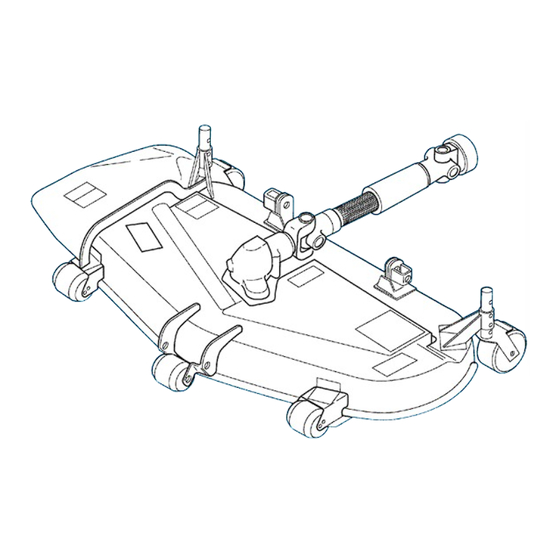
NAME OF MAJOR COMPONENTS NAME OF MAJOR COMPONENTS SSM60-TXG23E4F (1) Mower deck (2) Gear box (3) Universal joint (4) Discharge cover (5) Belt cover (LH) (6) Belt cover (RH) (7) Universal joint cover (8) Belt (9) Pulley (10) Tension arm (11) Blade (12) Front gauge wheel (13) Rear gauge wheel... -
Page 31: Ssm54-Txg23E4F
SSM48, SSM54, SSM60 & SMM54, SRM48, SRM54 SSM54-TXG23E4F (1) Mower deck (2) Gear box (3) Universal joint (4) Discharge cover (5) Belt cover (LH) (6) Belt cover (RH) (7) Universal joint cover (8) Belt (9) Pulley (10) Tension arm (11) Blade... -
Page 32: Ssm48-Txg23E4F
NAME OF MAJOR COMPONENTS SSM48-TXG23E4F (1) Mower deck (2) Gear box (3) Universal joint (4) Discharge cover (5) Belt cover (LH) (6) Belt cover (RH) (7) Universal joint cover (8) Belt (9) Pulley (10) Tension arm (11) Blade (12) Gauge wheel (13) Rollar FIG. -
Page 33: Smm54-Txg23E4F
SSM48, SSM54, SSM60 & SMM54, SRM48, SRM54 SMM54-TXG23E4F (1) Mower deck (2) Gear box (3) Universal joint (4) Belt cover (LH) (5) Belt cover (RH) (6) Universal joint cover (7) Belt (8) Pulley (9) Tension arm (10) Main blade (11) Sub blade... -
Page 34: Srm54-Txg23E4F
NAME OF MAJOR COMPONENTS SRM54-TXG23E4F (1) Mower deck (2) Gear box (3) Universal joint (4) Discharge cover (5) Belt cover (LH) (6) Belt cover (RH) (7) Universal joint cover (8) Belt (9) Pulley (10) Tension arm (11) Blade (12) Front gauge wheel (13) Rear gauge wheel (14) Rollar FIG. -
Page 35: Srm48-Txg23E4F
SSM48, SSM54, SSM60 & SMM54, SRM48, SRM54 SRM48-TXG23E4F (1) Mower deck (2) Gear box (3) Universal joint (4) Discharge cover (5) Belt cover (LH) (6) Belt cover (RH) (7) Universal joint cover (8) Belt (9) Pulley (10) Tension arm (11) Blade... -
Page 36: Installation On The Tractor
INSTALLATION ON THE TRACTOR INSTALLATION ON THE TRACTOR INSTALLATION OF MOWER DECK FIG. 5-1: NOTE: Place tractor on level, hard ground. Stop en- ● Before installing the mower deck, set height of all gine and remove engine key before mounting gauge wheel to lowest position 1.2”... - Page 37 SSM48, SSM54, SSM60 & SMM54, SRM48, SRM54 ● Before installing the mower deck on the tractor, as- semble the plate on the tractor’s transmission case for assembling the universal joint cover. (F-type) 1. Remove the 2 bolts from the transmission case, and detach the PTO shaft cover and bracket from the tractor as indicated on the FIGS.
-
Page 38: Assemble The Protector Only For Srm54/48
INSTALLATION ON THE TRACTOR FIG. 5-5 ASSEMBLE THE PROTECTOR ONLY FOR SRM54/48 8597-701-710-0 8597-701-710-0 PLATE/GUARD COMP PLATE/GUARD COMP V211-260-802-5 V211-260-802-5 V362-260-008-0 V362-260-008-0 BOLT/S BOLT/S NUT/M8 NUT/M8 M8X25 M8X25 FIG. 5-6... - Page 39 SSM48, SSM54, SSM60 & SMM54, SRM48, SRM54 Assemble COVER/PROTECTOR with PLATE/GUARD COMP by PLATE/ I /25X280 and NUT/M8. FIG. 5-7 Tighten up temporarily as cover will be attached on mower cover plate later. FIG. 5-8 Assemble the COVER/PROTECTOR as it is sand- wiched by PLATE COMP and PLATE/ I /25X184 and NUT/M8.
- Page 40 INSTALLATION ON THE TRACTOR PLATE COMP PLATE COMP ROPS frame ROPS frame COVER / PROTECTOR COVER / PROTECTOR PLATE/ I /25X184 PLATE/ I /25X184 NUT/M8 NUT/M8 FIG. 5-10 For all model 3. Turn the steering wheel. (If the mower deck is in- stalled from right side, turn the steering wheel to left side and vice versa.) FIG.
- Page 41 SSM48, SSM54, SSM60 & SMM54, SRM48, SRM54 4. Disengage the pin of gauge wheel on rearward of mower deck, then turn the wheel by 90 degree. (This procedure is for only SMM54, SRM48/54) FIG. 5-12 Make sure that 4WD wheel cover and mower gauge wheel are not touched with each other.
- Page 42 INSTALLATION ON THE TRACTOR 9. Assemble the PLATE/COVER/MID. FIG. 5-16 FIG. 5-17: ● The universal joint should be installed from side of tractor. ● Install universal joint of mower deck,1, onto mid PTO shaft of tractor as illustrated. CAUTION: Make sure that lock pin returns, as it should become so when universal joint fits onto PTO shaft completely.
- Page 43 SSM48, SSM54, SSM60 & SMM54, SRM48, SRM54 FIGS. 5-18,5-19,5-20,5-21: ● After assembling the universal joint on the tractor, attach the insulater on the cover, and assemble it on the tractor. 1. Attach the PROTECTOR (40),2 and the INSU- LATER (100),3 on the PLATE (COVER/MOWER),4 as indicated on the FIGS.
- Page 44 INSTALLATION ON THE TRACTOR 2. After attaching the universal joint on the tractor, assemble the PLATE (COVER/MOWER),4 on the tractor with the two NUT/WASHER,5 and the one BOLT, SEMS (SP),6 as indicated on the FIGS. 5-19,5-20. PLATE (COVER/MOWER) 8595-150-071-0A FIG. 5-21...
-
Page 45: Mower Operation
SSM48, SSM54, SSM60 & SMM54, SRM48, SRM54 MOWER OPERATION BEFORE OPERATION NOTE: Become familiar with how to operate mower and understand safety instructions by reading this manual and tractor’s manual carefully. IMPORTANT: The machine is equipped with vari- ous safety systems. All safety shields, guards, and covers should always be in position and functioning properly. - Page 46 MOWER OPERATION SRM54-TXG23E4F SRM48-TXG23E4F FIG. 6-3 8663-501-240-0 PIN/08X60 COMP FIG. 6-4...
- Page 47 SSM48, SSM54, SSM60 & SMM54, SRM48, SRM54 SSM48-TXG23E4F SSM54-TXG23E4F SSM60-TXG23E4F SRM48-TXG23E4F 8595-901-008-1D LABEL (GAUGE WHEEL) FIG. 6-5 SMM54-TXG23E4F SRM54-TXG23E4F 8658-901-031-0 LABEL (CUTTING) FIG. 6-6...
-
Page 48: Inspection And Service Of Each Part
INSPECTION AND SERVICE OF EACH PART INSPECTION AND SERVICE OF EACH PART INSPECTION AND REPLACEMENT OF THE GEAR 1) Inspection of oil level IMPORTANT: Check oil level after every 50 hours of operation. Remove the level plug located on the left side wall of the gear case. -
Page 49: Inspection And Replacement Of The Drive Belt
SSM48, SSM54, SSM60 & SMM54, SRM48, SRM54 a. Remove the mower blade which is attached the shaft of the gear case referring to the instructions for the replacement of the mower blades. b. Detach the drive shaft cover and both belt cover (LH and RH) by loosing the tightening nuts. -
Page 50: Stopping The Mower
INSPECTION AND SERVICE OF EACH PART 3) For preventing damage of turf a. Advance in a direction so that dust does not hit the operator by taking into consideration the direction of a. Mowing is desirable in the afternoon or late after- the wind. -
Page 51: Efficient Mowing
SSM48, SSM54, SSM60 & SMM54, SRM48, SRM54 EFFICIENT MOWING - Be sure to mow at full throttle. - Choose an adequate traveling speed in accordance with the height of grass to be cut. - Low cutting height will lead to poor mowing effi- ciency and rapid blade wear. - Page 52 INSPECTION AND SERVICE OF EACH PART b. Shift the lift lever to the down position. NOTE: Lower the mower until the gauge wheels land positively on the ground without fail. When the lift lever is released in an improper posi- tion, the mower will be hung in the air.
-
Page 53: Inspection And Replacement Of Vbelts
SSM48, SSM54, SSM60 & SMM54, SRM48, SRM54 INSPECTION AND REPLACEMENT OF V-BELTS SSM48-TXG23E4F 137±1mm SSM48-TXG23E4F 137±1mm FIGS. 7-4, 7-5, 7-6, 7-7, 7-8, 7-9: Check if belt is tensioned properly. When its tension is correct, clear- ance between coils of tension spring should be 0.04- 0.05”(1-1.2mm) or total length of tension spring when... -
Page 54: Belt Inspection
INSPECTION AND SERVICE OF EACH PART SRM48-TXG23E4F 137±1mm SRM48-TXG23E4F 137±1mm FIG. 7-8 SRM54-TXG23E4F 130±1mm SRM54-TXG23E4F 130±1mm FIG. 7-9 FIGS. 7-10 & 7-11: Belt Inspection. Check belt for damage and dirt. Remove belt covers, 1, and check belt. If they are smeared with oil, dirt, or wet with water, wipe them with a dry cloth. -
Page 55: Inspection And Replacement Of Blades
SSM48, SSM54, SSM60 & SMM54, SRM48, SRM54 INSPECTION AND REPLACEMENT OF BLADES Blade Removal CAUTION: Be sure to wear gloves to avoid cuts by blades. FIG. 7-12: Block blades by inserting a piece of wood, 1, between blade and mower deck. Loosen blade retain- ing nut with a 24-mm box end wrench. -
Page 56: Kind Of Blades
Install a washer on the blade and tighten the nut to the specified torque. 1300 kgf-cm Tightening torque: (94 ft-lbs) Kind of blades Model Parts code Mark SSM48 8595-306-055-10 I 8595E SSM54 8657-306-005-00 I 8657D SSM60 8654-306-006-10 I 8654C Main blade IE01-306-211-00 DI IE01A SMM54... -
Page 57: Lubrication And Greasing Points
SSM48, SSM54, SSM60 & SMM54, SRM48, SRM54 LUBRICATION AND GREASING POINTS The parts listed below should be lubricated periodi- cally with the lubricants specified. SSM60-TXG23E4F FIG. 8-1 Ref. No. Description Lubrication to be used Quantity Gear Box ISEKI Hypoid gear oil 80# 400 ±... -
Page 58: Ssm54-Txg23E4F
SSM54-TXG23E4F FIG. 8-2 Ref. No. Description Lubrication to be used Quantity Gear Box ISEKI Hypoid gear oil 80# 400 ± 20cc Center Metal Grease Inject until grease overflow from lip of upper oil seal Side Metal Tension Arm Wheel Fork... -
Page 59: Ssm48-Txg23E4F
SSM48, SSM54, SSM60 & SMM54, SRM48, SRM54 SSM48-TXG23E4F FIG. 8-3 Ref. No. Description Lubrication to be used Quantity Bevel Case ISEKI Hypoid gear oil 80# 400 ± 20cc Center Metal Grease Inject until grease overflow from lip of upper oil seal... -
Page 60: Smm54-Txg23E4F
SMM54-TXG23E4F FIG. 8-4 Ref. No. Description Lubrication to be used Quantity Gear Box ISEKI Hypoid gear oil 80# 400 ± 20cc Center Metal Grease Inject until grease overflow from lip of upper oil seal Side Metal Tension Arm Wheel Fork... -
Page 61: Srm54-Txg23E4F
SSM48, SSM54, SSM60 & SMM54, SRM48, SRM54 SRM54-TXG23E4F FIG. 8-5 Ref. No. Description Lubrication to be used Quantity Gear Box ISEKI Hypoid gear oil 80# 400 ± 20cc Center Metal Grease Inject until grease overflow from lip of upper oil seal... -
Page 62: Srm48-Txg23E4F
SRM48-TXG23E4F FIG. 8-6 Ref. No. Description Lubrication to be used Quantity Bevel Case ISEKI Hypoid gear oil 80# 400 ± 20cc Center Metal Grease Inject until grease overflow from lip of upper oil seal Side Metal Tension Arm Inject until grease overflow... -
Page 63: Disassembly And Reassembly
SSM48, SSM54, SSM60 & SMM54, SRM48, SRM54 DISASSEMBLY AND REASSEMBLY - As for the detachment of the mower from the tractor. remove the belt covers and other necessary parts to check the belts and other components for wear, damage, inspect or service each part if required. -
Page 64: Ssm60/54/48, Smm54, Srm54/48
DISASSEMBLY AND REASSEMBLY SSM60/54/48, SMM54, SRM54/48 FIG. 9-2 IMPORTANT: • Inspect the oil seals for wear and deformation. (Oil seals are funda- mentally consumable parts, so dis- assemble ones should be replaced with new ones.) • When installing the oil seal, take care not to allow the lips of the oil seal to turn up or the oil seal to be installed tilted. -
Page 65: Storing Of The Mower Deck
SSM48, SSM54, SSM60 & SMM54, SRM48, SRM54 STORING OF THE MOWER DECK a. Remove the mower deck from the tractor. b. Clean the mower deck. The special care to remove grass and dirt from the blades and the underside of the mower deck. -
Page 66: Troubleshooting
TROUBLESHOOTING TROUBLESHOOTING Troubles Presumable causes Remedies ・Drive belt is not installed properly ・Check belt and correct ・Blades are installed upside down ・Re-install them correctly ・Grass is too moist ・Wait until grass becomes dry ・Too tall grass ・Mow it in two steps ・Too dense grass ・Mow it in two step or narrow cut- ・Improper discharging... - Page 67 SSM48, SSM54, SSM60 & SMM54, SRM48, SRM54 Troubles Presumable causes Remedies ・Broken or unbalanced blades ・Replace them with new ones ・Loose blade tightening nuts ・Re-tighten them ・Clogged inside of mower or for- ・Clean eign matter caught in a pulley ・Excessive noise and vibration ・Broken belt...
-
Page 68: Packing Parts List
PACKING PARTS LIST PACKING PARTS LIST SSM60-TXG23E4F FIG.12-1 PART CODE PART NAME DECK/MOWER/60/TXG SET ARM/FRONT SET 8595-150-710-0A PLATE/COVER/MID COMP V211-361-005-0 BOLT/SP 8595-150-071-0 PLATE/COVER/MOWER 3680-155-005-0 PROTECTOR/040 3805-210-021-1A INSULATOR V362-260-008-0 NUT/M8 V211-360-801-6 BOLT, SEMS (SP) -
Page 69: Ssm54-Txg23E4F
SSM48, SSM54, SSM60 & SMM54, SRM48, SRM54 SSM54-TXG23E4F FIG.12-2 PART CODE PART NAME DECK/MOWER/54/TXG SET ARM/FRONT SET 8595-150-710-0A PLATE/COVER/MID COMP V211-661-005-0 BOLT/SP 8595-150-071-0A PLATE/COVER/MOWER 3680-155-005-0 PROTECTOR/040 3805-210-021-1A INSULATOR V362-260-008-0 NUT/M8 V211-360-801-6 BOLT, SEMS (SP) -
Page 70: Ssm48-Txg23E4F
PACKING PARTS LIST SSM48-TXG23E4F FIG.12-3 PART CODE PART NAME DECK/MOWER/TXG SET ARM/FRONT SET 8595-150-710-0A PLATE/COVER/MID COMP V211-661-005-0 BOLT/SP 8595-150-071-0A PLATE/COVER/MOWER 3680-155-005-0 PROTECTOR/040 3805-210-021-1A INSULATOR V362-260-008-0 NUT/M8 V211-360-801-6 BOLT, SEMS (SP) -
Page 71: Smm54-Txg23E4F
SSM48, SSM54, SSM60 & SMM54, SRM48, SRM54 SMM54-TXG23E4F FIG.12-4 PART CODE PART NAME DECK/MOWER/54/TXG SET ARM/FRONT SET 8595-306-006-0 SHIM/1.2 8658-306-003-0 PIN/PARALLEL 8595-150-710-0A PLATE/COVER/MID COMP V211-661-005-0 BOLT/SP 8595-150-071-0A PLATE/COVER/MOWER 3680-155-005-0 PROTECTOR/040 3805-210-021-1A INSULATOR V362-260-008-0 NUT/M8 V211-360-801-6 BOLT, SEMS (SP) -
Page 72: Srm54-Txg23E4F
PACKING PARTS LIST SRM54-TXG23E4F FIG.12-5 PART CODE PART NAME DECK/MOWER/54/TXG SET ARM/FRONT SET 8595-150-710-0A PLATE/COVER/MID COMP V211-661-005-0 BOLT/SP 8595-150-071-0A PLATE/COVER/MOWER 3680-155-005-0 PROTECTOR/040 3805-210-021-1A INSULATOR V211-360-801-6 BOLT, SEMS (SP) 8597-701-710-0 PLATE/GUARD COMP V211-360-802-5 BOLT, SEMS 8597-701-072-0A COVER/PROTECTOR 8666-701-002-0 PLATE/ I /25x280 8597-701-720-0A PLATE COMP 8597-701-071-0 PLATE/ I /25x184... -
Page 73: Srm48-Txg23E4F
SSM48, SSM54, SSM60 & SMM54, SRM48, SRM54 SRM48-TXG23E4F FIG.12-6 PART CODE PART NAME DECK/MOWER/48/TXG SET ARM/FRONT SET 8595-150-710-0A PLATE/COVER/MID COMP V211-661-005-0 BOLT/SP 8595-150-071-0A PLATE/COVER/MOWER 3680-155-005-0 PROTECTOR/040 3805-210-021-1A INSULATOR V211-360-801-6 BOLT, SEMS (SP) 8597-701-710-0 PLATE/GUARD COMP V211-360-802-5 BOLT, SEMS 8597-701-072-0A COVER/PROTECTOR... - Page 74 DECLARATION OF CONFORMITY ISEKI & CO., LTD. 3-14 Nishi-Nippori 5-Chome Arakawa-ku 116-8541 Tokyo Japan declare under our sole responsibility that the products described below. Generic denomination: Agricultural machine Function: Agricultural, forestry use and ground care TXG237 SSM48 SSM54 SMM54 SSM60...
- Page 76 SSM48 SSM54 SSM60 SMM54 SRM48 SRM54 Overseas Business Division 3-14, Nishi-Nippori, 5-chome, Arakawa-ku, Tokyo 116-8541, Japan Phone: (03) 5604-7658 Fax: (03) 5604-7703 OM-SMM54F-TXG237/-EN-10 1010-01-XXX Printed in Japan...
Need help?
Do you have a question about the SSM48 and is the answer not in the manual?
Questions and answers