
Summary of Contents for Koch PxtMX
- Page 1 Energizing Productivity Aufsteckmodul PxtMX Plug-on module PxtMX Betriebsanleitung Operating manual...
- Page 2 We reserve the right to make technical changes. Due to the product's further development, the diagrams and technical data used/indicated in this operating manual may be slightly different from the current status. V1.0DE/EN Betriebsanleitung Aufsteckmodul PxtMX / Operating manual Plug-on module PxtMX V1.0DE/EN...
-
Page 3: Table Of Contents
Aufsteckmodul PxtMX transportieren ........ - Page 4 Aufsteckmodul PxtMX reparieren ........
-
Page 5: Einführung
Grundsätzliches Die Betriebsanleitung ist in einzelne Kapitel unterteilt. Beachten Sie Folgendes: • Lesen Sie vor dem ersten Gebrauch des Aufsteckmoduls PxtMX diese Betriebsan- leitung sorgfältig und vollständig durch. Während des Gebrauchs ist es dafür zu spät! • Bemühen Sie sich, sie zu verstehen. Erst danach sind Sie in der Lage, das Aufsteck- modul PxtMX sicher und bestimmungsgemäß... -
Page 6: Abkürzungen
Hauptschalter einschalten. Lampe leuchtet. Bildpositionen und Wichtige Details werden in Grafiken mit Nummern (z. B. ) gekennzeichnet. Bild-Text-Bezug Im Text erfolgt der Bezug zu dieser Position durch diese Nummer hinter dem zugehörigen Detail. Betriebsanleitung Aufsteckmodul PxtMX V1.0DE/EN... -
Page 7: Definitionen
Risikograd, die leichte Verletzungen zur Folge haben kann. Beispiel für einen handlungsbezogenen Warnhinweis: Lebensgefahr durch elektrischen Strom! Vor dem Austausch der Sicherung den Hauptschalter ausschalten. Sachschaden Gefahren mit möglichen Sachschäden werden wie folgt gekennzeichnet: Piktogramm Hinweis auf Sachschaden. Betriebsanleitung Aufsteckmodul PxtMX V1.0DE/EN... - Page 8 1 Einführung Information Zusätzliche Informationen werden wie folgt gekennzeichnet: Piktogramm Hinweis auf Zusätzliche Hilfestellungen oder weitere nützliche Informationen. Applikation In dieser Betriebsanleitung wird „Applikation“ stellvertretend für „Antriebseinheit mit Frequenzumrichter“ oder „Servoantrieb“ verwendet. Betriebsanleitung Aufsteckmodul PxtMX V1.0DE/EN...
-
Page 9: Gerätebeschreibung
Leistungsauswertung ausgestattet werden. Neben seinen hardwaregebundenen Grundfunktionen (z. B. Digital-I/O-Schnittstelle) hat das PxtMX eine übergeordnete Funktion, deren Ziel es ist, die Geräte des Ener- giemanagements zu verbinden, die Kommunikation zu vereinfachen und zielgerich- tet an die Applikationsanforderungen anzupassen. Zu diesem Zweck fungiert es als Gateway und verbindet eine SPS über Feldbus (z. -
Page 10: Angewandte Richtlinien
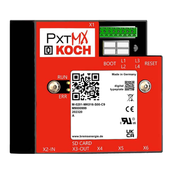
2 Gerätebeschreibung Angewandte Richtlinien Das Aufsteckmodul PxtMX erfüllt die grundlegenden Anforderungen der Richtlinie 2014/35/EU (Niederspannungsrichtlinie) und der Richtlinie 2014/30/EU (EMV-Richt- linie) Die Geräte sind nach UL 61800-5-1 zertifiziert. Typenbezeichnung M-0201-MK016-S00-C9 • Prüfsumme • Parametersatz • Stromgrenze des Netzanschlusses • Kennung •... -
Page 11: Übersichtsbilder
2 Gerätebeschreibung Übersichtsbilder Gehäuseansicht 2.4.1 Fig. 1: Gehäuseansicht PxtMX an einem PxtFX-Gerät PxtMX PxtMX, Frontansicht PxtMX mit Feldbus-Anschluss Betriebsanleitung Aufsteckmodul PxtMX V1.0DE/EN... -
Page 12: Funktionsübersicht
Das Gehäuse wird mit 2 Schrauben an der Frontseite der PxtXX-Gehäuse befestigt und bietet Platz für zusätzliche und unterschiedliche Module. Die Spannungsversor- gung des PxtMX erfolgt bei Befestigung an einem PxtXX über die interne Steckver- bindung. Alle zur Verfügung stehenden Interface-Stecker sind nach oben oder vorne herausgeführt und frei zugänglich. -
Page 13: Anschlüsse Oben
• Eingangspegel zwischen 0 und 0,7 Volt werden als LOW-Signale ausgewertet. Digitaleingänge: • Eingangspegel zwischen 2,7 und 24 Volt werden als HIGH-Signale ausgewertet. • Eingangspegel zwischen 0,7 und 2,7 Volt werden als undefiniert eingestuft und bewirken keine Veränderung des zuvor ausgelösten Status. Betriebsanleitung Aufsteckmodul PxtMX V1.0DE/EN... -
Page 14: Anschlüsse Unten
Fig. 6: Anschlüsse unten PxtMX (mit Feldbus) PxtMX (ohne Feldbus) Stecker X2 (Feldbus-Anschluss IN) Micro-SD-Karteneinschub Stecker X3 (Feldbus-Anschluss OUT) Stecker X4 (Mini-USB-Schnittstelle) Stecker X5 (Strommesswandler) Stecker X6 (K-Bus-Schnittstelle) Betriebsanleitung Aufsteckmodul PxtMX V1.0DE/EN... - Page 15 Möglichkeit der Protokollierung von Daten und der Systemsteuerung. Die Feldbusse stehen in unterschiedlichen Ausführungen als Schnittstelle zur Ver- fügung und bieten aktuell die Option EtherCAT zur Kommunikation mit dem PxtMX an. Die Steckerbelegung ist abhängig von der eingesetzten Steckmodulkarte und muss der zugehörigen Dokumentation entnommen werden.
-
Page 16: Typenschild
Seriennummer, dem Fertigungsdatum und der Hardware-Revision in digitaler Form. Die sogenannte "digital typeplate" ist der Zugang zu einer Web-Anwendung der Michael Koch GmbH, die weitere Informationen zu dem gescannten Gerät zur Verfügung stellt. Ist die Web-Anwendung durch Scannen des "digital typeplate code" geöffnet, muss ... -
Page 17: Elektrische Anschlusswerte
2 Gerätebeschreibung Elektrische Anschlusswerte Schutzart: IP20. Stromversorgung: über internen Stecker aus dem PxtXX oder über externes Netzteil. 2.10 Abmessungen 2.10.1 PxtMX Fig. 8: Abmessungen PxtMX Betriebsanleitung Aufsteckmodul PxtMX V1.0DE/EN... -
Page 18: Pxtmx Mit Feldbus-Anschluss
2 Gerätebeschreibung 2.10.2 PxtMX mit Feldbus-Anschluss Fig. 9: Abmessungen PxtMX mit Feldbus-Anschluss Betriebsanleitung Aufsteckmodul PxtMX V1.0DE/EN... -
Page 19: Grundlegende Sicherheitshinweise
Eine eigenständige Veränderung der Geräteparameter ohne Rücksprache mit der Michael Koch GmbH führt zum Haftungsausschluss. Gehäuse Das Gehäuse darf nicht geöffnet werden. Funktionsstörungen In der Nähe des PxtMX dürfen keine elektrischen Geräte benutzt werden, die die Funktion des PxtMX beeinflussen können. Betriebsanleitung Aufsteckmodul PxtMX V1.0DE/EN... -
Page 20: Transport / Lagerung / Montage
4 Transport / Lagerung / Montage RANSPORT AGERUNG ONTAGE Lieferung prüfen Das Aufsteckmodul PxtMX verlässt das Werk in geprüftem und einwandfreiem Zustand. Ein Verpackungsschild befindet sich außen auf der Verpackung. Transport- schäden sind von der Transportfirma zu verantworten. Lieferumfang: • 1 × Aufsteckmodul PxtMX •... -
Page 21: Aufsteckmodul Pxtmx Montieren
• Die Montage erfolgt direkt auf der am PxtFX oder PxtRX vorgesehenen Montage- fläche. Montage Fig. 10: Montage Das Gerät PxtRX oder PxtFX, an dem das PxtMX montiert werden soll, ausschalten. 2 Schrauben lösen und das Metallemblem entfernt. ... -
Page 22: Inbetriebnahme
24 V extern ±15% (min. 8 V, wenn nur parametrisiert werden soll). Pin 3 - 8 Über die digitalen Ein- und Ausgänge können bestimmte Funktionen ein- oder umgeschaltet und Statusmeldungen ausgewertet werden. Neben den nachfolgend aufgeführten Standardfunktionen sind die möglichen Optionen aufgabenabhängig und müssen gegebenenfalls definiert werden. Betriebsanleitung Aufsteckmodul PxtMX V1.0DE/EN... -
Page 23: Externe Spannungsversorgung Zur Parametrisierung
5 Inbetriebnahme 5.1.1 Externe Spannungsversorgung zur Parametrisierung Das PxtMX kann unabhängig von einem Basisgerät (PxtFX / PxtRX) und außerhalb des Montagebereichs parametrisiert werden. Benötigt wird ein Steckernetzteil mit min. 8 Volt Gleichspannung. Fig. 12: Parametrisierung 5.1.2 Digital Out 1 - 3 An Pin 3, 4 und 5 liegen die Digitalausgänge auf. - Page 24 5 Inbetriebnahme Fig. 13: Digital Out 1 - 3 Betriebsanleitung Aufsteckmodul PxtMX V1.0DE/EN...
-
Page 25: Digital In 1 - 3
Spannungsband können sowohl High als auch Low gemessen werden. Ein Betrieb in diesem Bereich ist zu vermeiden! Über die Digital-Eingänge kann z. B. eine von einem übergeordneten System ausge- gebene Freigabe für das PxtXX-System ausgewertet werden. Fig. 14: Digital In 1 - 3 Betriebsanleitung Aufsteckmodul PxtMX V1.0DE/EN... -
Page 26: Stecker X4 Anschließen (Mini-Usb-Schnittstelle)
5 Inbetriebnahme Stecker X4 anschließen (Mini-USB-Schnittstelle) Das PxtMX verfügt standardmäßig über eine integrierte ICI-Schnittstelle (Integrated Communication Interface) mit einem Micro-USB-Anschluss zur Verbindung mit ei- nem externen PC und ermöglicht eine Übertragung von Daten an und vom internen K-Bus, z. B. über die Software PxtTerminal. -
Page 27: Stecker X2 (In) Und X3 (Out) Anschließen (Feldbus)
Fig. 16: Stecker X2 und X3 (Feldbus) Option: Stecker X5 anschließen (Strommesswandler) Das Verbindungskabel wird anschlussfertig konfektioniert und mit 10 Meter Standardlänge ausgeliefert. Bei größeren Längen ist eine Rücksprache mit der Michael Koch GmbH erforderlich. Fig. 17: Stecker X5 Betriebsanleitung Aufsteckmodul PxtMX V1.0DE/EN... -
Page 28: Betriebsanzeigen L1 Bis L4
Gerät ist Master • In einem Verbund kann es immer nur (LED leuchtet) einen Master geben. • Bei Nutzung des PxtMX wird dieses immer zum Master. • In einem Verbund übernimmt der Master die Kommunikation und koordiniert die als Slave eingeteilten Geräte. -
Page 29: Firmwareupdate Installieren
• Mindestens eine Fehlermeldung liegt (LED leuchtet) vor. Firmwareupdate installieren Die PxtMX-Geräte werden mit einer zum Gerätetyp passenden Firmware ausgeliefert. Soll ein Firmware-Update durchgeführt werden, sind folgende Schritte notwendig: Updatefile bei der Michael Koch GmbH anfordern. Das Updatefile wird auf einer Micro-SD-Speicherkarte bereitgestellt. -
Page 30: Fehler Beim Laden Der Software
Fehler beim Laden der Software Wird ein Update der Applikation ausgeführt bzw. versucht, und eine SD-Karte mit gültiger Applikations-Datei vom PxtMX registriert, wird das Update durch Betätigen der Taste BOOT in den Flash-Speicher geladen. Dem Ladevorgang sind mehrere Statusmeldungen zugeordnet, die den aktuellen La- dezustand beschreiben. - Page 31 Aufsteckmodul PxtMX warten Das Aufsteckmodul PxtMX muss nicht gewartet werden. Aufsteckmodul PxtMX reparieren Ein defektes Aufsteckmodul PxtMX kann nur vom Hersteller repariert werden. Aufsteckmodul PxtMX entsorgen Das Aufsteckmodul PxtMX an den Hersteller zurückschicken oder entsprechend den lokalen Bestimmungen entsorgen.
- Page 32 Notizen… Betriebsanleitung Aufsteckmodul PxtMX V1.0DE/EN...
- Page 33 Transporting the Plug-on module PxtMX ........
- Page 34 Maintaining the Plug-on module PxtMX ........
-
Page 35: Introduction
Working with this Operating manual 1.3.1 Target group This Operating manual is intended for qualified electricians who are to work with the Plug-on module PxtMX of Michael Koch GmbH in all life cycles. 1.3.2 Basic information This Operating manual is divided into chapters. -
Page 36: Abbreviations
Image items and Important details are marked with numbers (e.g. ) in diagrams. relationship between This is referred to in the text by this number after the associated detail. text and image Operating manual Plug-on module PxtMX V1.0DE/EN... -
Page 37: Definitions
Example of an action-related warning: Danger to life from electric current! Switch off the main switch before replacing the fuse. Property damage Dangers with possible property damage are identified as follows: Pictogram Instruction about Property damage. Operating manual Plug-on module PxtMX V1.0DE/EN... - Page 38 1 Introduction Information Additional information is identified as follows: Pictogram Instruction about Additional assistance or other useful information. Application Application" stands for "drive unit with frequency converter" or "servo drive" in this Operating manual. Operating manual Plug-on module PxtMX V1.0DE/EN...
-
Page 39: Description Of The Device
Both variants are in their own housing and are simply plugged and screwed onto the PxtXX housing. In its main function, the PxtMX should work as a gateway and generally provide the option of communication. For this purpose, the PxtMX has an integrated USB interface ICI for data visualisation and access to important parameters, as well as a customised fieldbus connection (e.g. -
Page 40: Applied Guidelines
2 Description of the device Applied guidelines The Plug-on module PxtMX fulfils the basic requirements of Directive 2014/35/EU (Low Voltage Directive) and Directive 2014/30/EU (EMC Directive). The devices are certified to UL 61800-5-1. Type designation M-0201-MK016-S00-C9 • Checksum • Parameter set •... -
Page 41: Overview Diagrams
2 Description of the device Overview diagrams 2.4.1 Housing view Fig. 1: Housing view PxtMX on a PxtFX device PxtMX PxtMX, front view PxtMX with fieldbus connection Operating manual Plug-on module PxtMX V1.0DE/EN... -
Page 42: Function Overview
Layout Fig. 3: Layout The PxtMX module is mounted as an additional box on the front of the PxtXX energy management systems. The connection is made via an integrated connector strip. The enclosure is attached to the front of the PxtXX enclosures with 2 screws and offers space for additional and different modules. -
Page 43: Top Connections
• Input levels between 2.7 and 24 volts are evaluated as HIGH signals. • Input levels between 0.7 and 2.7 volts are classified as undefined and do not cause a change in the previously triggered status. Operating manual Plug-on module PxtMX V1.0DE/EN... -
Page 44: Bottom Connections
Fig. 6: Bottom connections PxtMX (with fieldbus) PxtMX (without fieldbus) Connector X2 (fieldbus connection IN) Micro SD card slot Connector X3 (fieldbus connection OUT) Connector X4 (mini USB interface) Connector X5 (current transformer) Connector X6 (K-bus interface) Operating manual Plug-on module PxtMX V1.0DE/EN... - Page 45 2 Description of the device Connector X2 and X3 Only the PxtMX with fieldbus interface is prepared for fieldbus communication and (fieldbus connections) offers the possibility of logging data and system control. The fieldbuses are available in different versions as interfaces and currently offer the EtherCAT option for communication with the PxtMX.
-
Page 46: Type Plate
The large (left) code contains the same information for the type designation, the serial number, the production date and the hardware revision in digital form. The so-called digital typeplate is the access to a web application of Michael Koch GmbH, which provides further information about the scanned device. -
Page 47: Electrical Supply Data
2 Description of the device Electrical supply data Protection class: IP20. Power supply: via internal plug from the PxtXX or via external power supply unit. 2.10 Dimensions 2.10.1 PxtMX Fig. 8: Dimensions of PxtMX Operating manual Plug-on module PxtMX V1.0DE/EN... -
Page 48: Pxtmx With Fieldbus Connection
2 Description of the device 2.10.2 PxtMX with fieldbus connection Fig. 9: Dimensions of PxtMX with fieldbus connection Operating manual Plug-on module PxtMX V1.0DE/EN... -
Page 49: Basic Safety Instructions
• Follow the instructions from your managers and first-aid staff. The device Functional status The Plug-on module PxtMX may only be operated in a fully functional state. Before using it, ensure that the PxtMX is in proper working condition. Shock or The PxtMX must not be subjected to any shock or vibration loads. -
Page 50: Transport / Storage / Installation
TORAGE NSTALLATION Checking the delivery The Plug-on module PxtMX leaves the factory in a tested and perfect condition. There is a packing label on the outside of the packaging. Any transport damage is the responsibility of the transport company. Scope of delivery: •... -
Page 51: Installing The Plug-On Module Pxtmx
• The device is mounted directly on the mounting surface provided on the PxtFX or PxtRX. Installation Fig. 10: Installation Switch off the PxtRX or PxtFX device on which the PxtMX is to be mounted. Loosen 2 screws and remove the metal emblem ... -
Page 52: Commissioning
Via the digital inputs and outputs, certain functions can be switched on or over and status messages can be evaluated. In addition to the standard functions listed below, the possible options depend on the task and may have to be defined. Operating manual Plug-on module PxtMX V1.0DE/EN... -
Page 53: External Power Supply For Parameterisation
5 Commissioning 5.1.1 External power supply for parameterisation The PxtMX can be parameterised independently of a base device (PxtFX / PxtRX) and outside the installation area. A plug-in power supply with min. 8 volts DC is required. Fig. 12: Parameterisation 5.1.2... - Page 54 5 Commissioning Fig. 13: Digital Out 1 - 3 Operating manual Plug-on module PxtMX V1.0DE/EN...
-
Page 55: Digital In 1 - 3
Operation in this area is to be avoided! Via the digital inputs, for example, a release issued by a higher-level system can be evaluated for the PxtXX system. Fig. 14: Digital In 1 - 3 Operating manual Plug-on module PxtMX V1.0DE/EN... -
Page 56: Connecting Connector X4 (Mini-Usb Interface)
5 Commissioning Connecting connector X4 (mini-USB interface) The PxtMX has an integrated communication interface (ICI) as standard with a micro- USB port for connection to an external PC and allows data to be transferred to and from the internal K-Bus, e.g. via the PxtTerminal software. -
Page 57: Connecting Connector X2 (In) And X3 (Out) (Field Bus)
Optional: Connecting connector X5 (current transformer) The connecting cable is assembled ready for connection and supplied with 10 metres of standard length. For longer lengths, consultation with Michael Koch GmbH is required. Fig. 17: Connector X5 Operating manual Plug-on module PxtMX... -
Page 58: Operation
• Current sensor faulty (optional). • Fieldbus error (optional). • Additional errors. Blue Master determination • The PxtMX present in the network is (LED is flashing) used as the master. • The address is the serial number of the device. -
Page 59: Installing The Firmware Update
(LED lights up) Installing the firmware update The PxtMX devices are delivered with firmware that matches the device type. If a firmware update is to be carried out, the following steps are necessary: Request an update file from Michael Koch GmbH. -
Page 60: Error When Loading The Software
Error when loading the software If an update of the application is executed or attempted and an SD card with a valid application file is registered by the PxtMX, the update is loaded into the flash memory by pressing the BOOT key. - Page 61 Repairing the Plug-on module PxtMX A faulty Plug-on module PxtMX can only be repaired by the manufacturer. Disposing of the Plug-on module PxtMX Return the Plug-on module PxtMX to the manufacturer or dispose of it according to local regulations.
- Page 62 Notes… Operating manual Plug-on module PxtMX V1.0DE/EN...
- Page 63 Notes… Operating manual Plug-on module PxtMX V1.0DE/EN...
Need help?
Do you have a question about the PxtMX and is the answer not in the manual?
Questions and answers