
Related Manuals for LEYBOLD LEYSPEC view Series


Summary of Contents for LEYBOLD LEYSPEC view Series
- Page 1 LEYSPEC Residual Gas Analyzer (RGA) Hardware Manual 300781172_002_C0 Part Numbers 220010V01 220011V01 220012V01 220013V01 220020V01 220021V01...
-
Page 3: Table Of Contents
Degassing Secondary electron multiplier (SEM) tube Baking Calibration Converting to partial pressure Storage Options 10.1 AC adaptor 10.2 USB 3.0 wired LAN adaptor 10.3 Switching hub Maintenance 11.1 Life expectancy of the ion source 300781172_002_C0 - 01/2019 - © Leybold... - Page 4 13.4 Interpretation of measurement value 13.5 Peaks of major residual gases 13.6 Setting the IP address of the sensor unit 13.7 Set up the RGA PC network Return the equipment or components for service 300781172_002_C0 - 01/2019 - © Leybold...
-
Page 5: Before Using This Instrument
CAUTION: No part of this manual shall be copied for a third party without consent by Leybold in writing. Safety symbols Important safety information is highlighted as WARNING and CAUTION instructions;... - Page 6 Connect the product to A-class grounding to prevent electrical leakage. WARNING: For safety reason, do not touch the metal parts of a terminal, which could be energized with a voltage. Touching the metal parts could cause electric shock. 300781172_002_C0 - 012/2019 - © Leybold...
- Page 7 WARNING: Before you switch on the power, make sure that the sensor unit and analyzer tube are correctly connected. If power is turned on without connecting the analyzer tube, components could be damaged. 300781172_002_C0 - 01/2019 - © Leybold...
- Page 8 When disposing of this product, dispose of it according to your local government regulations. If the analyzer tube or its parts were used in an environment that can affect the human health or the environment, dispose of them through an approved method. 300781172_002_C0 - 012/2019 - © Leybold...
- Page 9 Connect the product to A-class grounding to prevent electrical leakage. WARNING: Before turning on power, make sure that the operating voltage and supply voltage are the same. If incorrect power is applied, damage or fire could result. 300781172_002_C0 - 01/2019 - © Leybold...
- Page 10 When disposing this AC adaptor, dispose it according to your local government regulations. If the analyzer tube or its parts were used in an environment that can affect the human body, dispose of them through an approved method. 300781172_002_C0 - 012/2019 - © Leybold...
-
Page 11: Introduction
Introduction Introduction The Leybold range of Residual Gas Analyzers include: 1. LEYSPEC view models Application: Residual gas analysis and leak test of sputtering system, vacuum evaporation system, and so forth. 2. LEYSPEC ultra models Application: R&D, residual gas analysis and leak test of sputtering systems, vacuum coaters and others. -
Page 12: Specifications And Configurations
D-SUB 15-pin (M2.6 screw) Communication connector RJ45 female Fuse 6.3 A Weight (analyzer tube) (kg) 0.55 0.64 0.55 0.64 0.81 Weight (sensor unit) (kg) 2.1 (without SEM) 2.2(with SEM) IP protection class IP30 (sensor unit) 300781172_002_C0 - 012/2019 - © Leybold... - Page 13 ¤ TCP / IP communication can be used only with on wired connection with a Windows PC with dedicated software installed. Only Windows PC devices are supported. 300781172_002_C0 - 01/2019 - © Leybold...
-
Page 14: Standard Configuration
Specifications and configurations Standard configuration 2.2.1 LEYSPEC view models Item Quantity Sensor unit Sensor tube Software and instruction manual CD AC/DC adaptor LAN cable Fig. 2.1 LEYSPEC view dimensions 300781172_002_C0 - 012/2019 - © Leybold... - Page 15 Specifications and configurations 2.2.2 LEYSPEC ultra models Fig. 2.2 LEYSPEC ultra dimensions 2.2.3 LEYSPEC view100/LEYSPEC view200 (with analyzer tube) Fig. 2.3 LEYSPEC view100/LEYSPEC view200 (with analyzer tube) dimensions 300781172_002_C0 - 01/2019 - © Leybold...
- Page 16 LEYSPEC view100S/LEYSPEC view200S (with analyzer tube) Fig. 2.4 LEYSPEC view100S/LEYSPEC view200S (with analyzer tube) dimensions 2.2.5 LEYSPEC ultra 200S/LEYSPEC ultra 300S (with analyzer tube) Fig. 2.5 LEYSPEC ultra 200S/LEYSPEC ultra 300S (with analyzer tube) dimensions 300781172_002_C0 - 012/2019 - © Leybold...
-
Page 17: Buttons And Connections
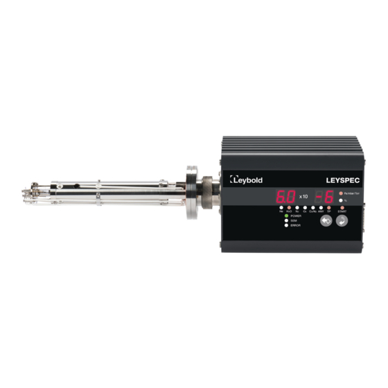
Measurement start button (START) Starts measurement. The upper orange LED indicates that measurement has started. Measurement value units display The unit of measured partial pressure. For the display shows a percentage (%). 300781172_002_C0 - 01/2019 - © Leybold... -
Page 18: Rear Panel
Ethernet connector (LAN) RJ45 connector (8-pole 8-wire) for connecting the LAN cable. Ethernet communication connector provides a wired connection for a Windows PC with dedicated software installed. Only Windows PCs are supported. 300781172_002_C0 - 012/2019 - © Leybold... -
Page 19: Ext-I/O Connector
) because power is not supplied to the input operational amplifier. If another recorder is connected in parallel with the RGA's analogue input, the input voltage to that recorder may fluctuate due to this undefined impedance. 300781172_002_C0 - 01/2019 - © Leybold... -
Page 20: Dip Switch
To set the sensor address for this RGA unit. See the table below for switch settings. Address Address (0: OFF, 1: ON) The following tables show the factory default switch settings (multiple sensor unit option excluded). 300781172_002_C0 - 012/2019 - © Leybold... - Page 21 : 192.168.250.22 Sensor 5 : 192.168.250.15 Sensor 13 : 192.168.250.23 Sensor 6 : 192.168.250.16 Sensor 14 : 192.168.250.24 Sensor 7 : 192.168.250.17 Sensor 15 : 192.168.250.25 Sensor 8 : 192.168.250.18 Sensor 16 : 192.168.250.26 300781172_002_C0 - 01/2019 - © Leybold...
-
Page 22: Installation
This can cause measurement errors or filament burnout. Front panel buttons and displays As indicated in on page 17, fix the analytical tube after paying attention to the orientation of the operation panel 300781172_002_C0 - 012/2019 - © Leybold... - Page 23 This can cause the sensor unit to malfunction. Fig. 4.1 Pin assignment as viewed from atmospheric side (LEYSPEC view) LEYSPEC view FIL1 Grid FIL2 FIL.C IC (SEM/FC) IC (FC) LEYSPEC view 300781172_002_C0 - 01/2019 - © Leybold...
- Page 24 Check filament continuity from FIL1 to FIL.C and from FIL2 to FIL.C. Ω. Measure the resistance. If the filaments are intact, the resistance is about 1 If the filament is broken, the resistance is infinite (open circuit). 300781172_002_C0 - 012/2019 - © Leybold...
- Page 25 1. Wire the power connector as follows: Power +24 V Pin that supplies 24 V d.c. power. Power GND GND when +24 V d.c. power is supplied. 300781172_002_C0 - 01/2019 - © Leybold...
- Page 26 Connect multiple sensors to the PC To connect more than one sensor unit, use a switching hub. For each sensor unit DIP switch set a separate sensor number (individual IP address) by referring to page 20. 300781172_002_C0 - 012/2019 - © Leybold...
- Page 27 Installation LAN connector LAN cable Sensor unit Switching hub Sensor unit (maximum 16 units) Fig. 4.5 Connection between PC and multiple sensor units 300781172_002_C0 - 01/2019 - © Leybold...
-
Page 28: Turning On (Supplying Power)
Remote Mode (Default) The "POWER" LED lights up. No indication on the display. Local Mode The "POWER" and "Pa" LED lights up. 0.0 x 10 is shown on the display as “0.0” and “-0”. 300781172_002_C0 - 012/2019 - © Leybold... -
Page 29: Operation
11.Click measure MES to start gas analysis. The S and M lights come on. (Whether the F, R and S lights are on or off depends on the settings on the control panel.) 300781172_002_C0 - 01/2019 - © Leybold... -
Page 30: Measurement With The Sensor Unit (Local Mode)
Add firewall rules to allow RGA communications on page 88. Measurement with the sensor unit (Local mode) With measurement stopped, set DIP switch 4 to ON. Front panel operation Conduct gas analysis referring to on page 31. 300781172_002_C0 - 012/2019 - © Leybold... -
Page 31: Front Panel Operation
Fig. 7.1 Front panel operation MESU - 2 Partial pressure is shown in the display during measurement. Pressing the CH button changes over the measurement gas species from He to O, N ration (%), ANY and TP. 300781172_002_C0 - 01/2019 - © Leybold... -
Page 32: If Pressure Is Lower Than Measurement Range
If filament fault has occurred Err. - 1 If any fault occurs with filament 1 when the START button is ON, the sign "F1" is shown. ("F2" is shown for filament 2 where present). 300781172_002_C0 - 012/2019 - © Leybold... -
Page 33: If Rf Fault Has Occurred
If interlock signal is input and total pressure interlock in on Err. - 4 If the interlock signal is input when the START button is ON, the sign "Prot" is shown on the display. 300781172_002_C0 - 01/2019 - © Leybold... - Page 34 Front panel operation The sign "Prot" could be also shown even when instantaneous pressure rise immediately after filament turns on. 300781172_002_C0 - 012/2019 - © Leybold...
-
Page 35: External Inputs And Outputs (I/O)
When the unit is in its error state, the error LED lights red. The unit keeps its interlock error state until the error is confirmed by the dedicated gas analysis software. This means that even when the interlock signal is not active, the interlock may be displayed as an error. 300781172_002_C0 - 01/2019 - © Leybold... -
Page 36: Analogue Input
(several ?) because power is not supplied to the input operational amplifier. If another recorder is connected in parallel with the RGA's analogue input, the input voltage to that recorder may fluctuate due to this undefined impedance. 300781172_002_C0 - 012/2019 - © Leybold... -
Page 37: Cautions In Operation
Ions that have passed through the quadrupole are incident on the SEM. Ions are incident on the metal surface on the 1st stage through the ion entrance port in the SEM, and secondary electrons are discharged. The secondary electrons are 300781172_002_C0 - 01/2019 - © Leybold... - Page 38 2. In the software control panel, set the detector to SEM and measure the ion current value of the desired mass number. 3. Perform the same measurement as in (2) by switching detector to FC. 300781172_002_C0 - 012/2019 - © Leybold...
-
Page 39: Baking
6. The temperature and time of baking depend on conditions. As a guide, bake at around 150 °C for 12 hours. Always control the temperature using a thermocouple or similar so that the analyzer tube will not be damaged by excessive temperature rises. 300781172_002_C0 - 01/2019 - © Leybold... -
Page 40: Calibration
For the relationship between mass numbers and ions, refer to Appendix "Peaks of Major Residual Gases". In the dedicated gas analysis software, use the analogue mode recipe to perform mass number calibration. Refer to the software instructions for further details. 300781172_002_C0 - 012/2019 - © Leybold... - Page 41 , the insulation may be held acceptable in normal sense, but in a micro-current measurement such as by an μ ionization gauge, a leakage current of 0.75 A would flow from the grid electrode. 300781172_002_C0 - 01/2019 - © Leybold...
-
Page 42: Converting To Partial Pressure
With a pumping system which can reach 1 x 10 Pa or less, select method 1) or 3) because the total pressure measurement range of LEYSPEC view models is from 1 x 10 to 1 x 10 300781172_002_C0 - 012/2019 - © Leybold... -
Page 43: Storage
If the instrument is not used for an extended time, store the analyzer tube in an inert gas atmosphere like nitrogen. If the analyzer tube is stored in a high humidity atmosphere, the SEM may deteriorate. 300781172_002_C0 - 01/2019 - © Leybold... -
Page 44: Options
MTBF 100,000 hours minimum at maximum load, 25 °C Applicable standard Safety standard: UL/c-UL (UL 60950-1: 2nd Edition), TUV/GS (EN 60950-1: 2nd Edition), EMI: FCC class B, EN 55022 and EN55024 class B, CE 300781172_002_C0 - 012/2019 - © Leybold... - Page 45 2. Make sure that the AC adaptor has not been damaged in transit. CAUTION: Make connections to the correct pins when wiring the power connector. If you apply power to the incorrect pins internal damage could result. 300781172_002_C0 - 01/2019 - © Leybold...
- Page 46 Fig. 10.3 Sensor unit power supply connectors +V (P (+) ) Positive polarity 24 V d.c. - white cable -V (N (-) ) Negative polarity of 24 V d.c. - black cable Frame GND ( Frame ground - green cable 300781172_002_C0 - 012/2019 - © Leybold...
-
Page 47: Usb 3.0 Wired Lan Adaptor
(1:1) or crossover cables. We recommended you use shielded LAN cables. CAUTION: The maximum length of the LAN cable used for connection between sensor unit and PC is 100 m. 300781172_002_C0 - 01/2019 - © Leybold... - Page 48 Screw type connector Rated voltage 24 V d.c. Current consumption 275 mA at 24 V d.c. Interface RJ45 female connector, 16 pieces Maximum transmission 100 m distance Install Can be mounted on universal DIN rail 300781172_002_C0 - 012/2019 - © Leybold...
- Page 49 8-port power connector wiring Connect the 24 V d.c. power supply to the power supply connector of this unit Be sure to turn off the main power supply when connecting the power supply. 300781172_002_C0 - 01/2019 - © Leybold...
- Page 50 Connection as a redundant power supply Connection as single power supply 5. Connect the Ethernet cables. CAUTION: Make sure the power is off. 6. Plug in the power connector. 7. Plug in the power supply. 300781172_002_C0 - 012/2019 - © Leybold...
-
Page 51: Maintenance
If FIL1 has burnt out in a model having two filaments, change over the filament to FIL2. If both filaments have burnt out or if the ion source is severely contaminated, it is necessary to replace the ion source. Contact your local Leybold representative. - Page 52 4. Install a new ion source and fix it to the Q pole using the M2 screw. 5. Fix the FIL 1, FIL 2, FIL C, GAUGE and GRID wiring with M2 screw. 6. Fix the wiring using the wiring fixing band. 300781172_002_C0 - 012/2019 - © Leybold...
- Page 53 1. Loosen the M2 screws (A) of the FIL1, FIL2 and FIL.C joints using a small screwdriver and remove the terminals from the hermetic seal. 2. Remove the two M2 screws (circled) from the ion source post using a small screwdriver. 300781172_002_C0 - 01/2019 - © Leybold...
- Page 54 4. Set a new filament and fix it to the ion source using the M2 screws. 5. Reattach FIL1, FIL2 and FIL.C to the terminals and reattach to the hermetic seal. Fig. 11.2 Pin assign of atmospheric side view 300781172_002_C0 - 012/2019 - © Leybold...
- Page 55 1. Loosen the M2 screws (A) of the FIL1, FIL2 and FIL.C joints. 2. Loosen the M2 screws (circled) to remove the GRID, FOCUS and GAUGE wiring from the ion source. 3. Remove two M2 screws to remove the ion source. See Figures (3) and (4). 300781172_002_C0 - 01/2019 - © Leybold...
- Page 56 5. Remove the sockets connected to pins "l" and "m" from the analyzer tube base flange (A). Removing this pin separates the SEM from the base flange. The pin may break if a force is applied to the pin horizontally. 300781172_002_C0 - 012/2019 - © Leybold...
-
Page 57: Calibrate
1. Check that the pressure is less than 1 x 10 2. Connect a circuit tester to the TUNING socket on the back of the unit and set the tester to DC voltage mode. 300781172_002_C0 - 01/2019 - © Leybold... - Page 58 In Operation setting of FIL button, remove all the check marks except "RF". 5. Start measurement and confirm that you see a DC voltage on the circuit tester. 6. Turn the Resolution adjustment potentiometers on the sensor rear-panel to minimize the DC voltage. 7. Stop measurement. 300781172_002_C0 - 012/2019 - © Leybold...
- Page 59 3. Compare the measured spectrum with reference spectrum described (below) to see if adjustment is required. 4. Turn the Resolution adjustment potentiometers on the sensor rear-panel to adjust the resolution while confirming spectra. (L) Adjust low mass side 300781172_002_C0 - 01/2019 - © Leybold...
- Page 60 While you adjust the potentiometers keep track of the direction of rotation and number of rotations at all times. Fig. 11.3 Reference spectrum (LEYSPEC view100) Fig. 11.4 Reference spectrum (LEYSPEC view100S) 300781172_002_C0 - 012/2019 - © Leybold...
- Page 61 Maintenance Fig. 11.5 Reference spectrum (LEYSPEC view200/200S or LEYSPEC ultra 200S) m/z=1-10 Fig. 11.6 Reference spectrum (LEYSPEC view200/200S or LEYSPEC ultra 200S) m/z=101-200 Fig. 11.7 Reference spectrum (LEYSPEC ultra 300S) m/z=1-100 300781172_002_C0 - 01/2019 - © Leybold...
- Page 62 (temperature, humidity) change, or during a confirmation of sensitivity. Procedure: 1. Set a recipe for analogue mode and measure the mass spectrum. (If peaks are not clear, improve the situation by adding gas flow or increasing the SEM voltage.) 300781172_002_C0 - 012/2019 - © Leybold...
- Page 63 4. Set calibration points for several main peaks (m/z = 2, 18, 28, 32, 40, 44…). At least three points are required to calibrate. Mass numbers for points that you do not enter are estimated from extrapolation and interpolation. 5. From the File menu, select Send Calibration Data. 300781172_002_C0 - 01/2019 - © Leybold...
- Page 64 = 28) 3. Control settings From the Sensor menu, open Control Panel and make these settings: Ion collector = FC Emission current = μ A LEYSPEC view models (fixed value) μ A LEYSPEC ultra models 300781172_002_C0 - 012/2019 - © Leybold...
- Page 65 (Degas is cleaning function which removes deposition from surface of electrode by colliding high energy thermal electrons.) If the sensitivity is not improved after degassing, consider exchanging the ion source. IonCurrent Sensitivit essure 300781172_002_C0 - 01/2019 - © Leybold...
- Page 66 7. Check the sensitivity again after degassing. If after degassing, the ion current is below 1 x 10 A/Pa by more than one order of magnitude, consider degassing for a longer time with a greater current or consider replacing the ion source. 300781172_002_C0 - 012/2019 - © Leybold...
- Page 67 1. Flow gas into the sensor until target pressure. After that, start measurement and confirm total pressure. 2. Calculate the coefficient. Coefficient = vacuum gauge [Pa] / total pressure of the RGA [Pa] 3. From the Sensor menu, select TP coefficient setting. 300781172_002_C0 - 01/2019 - © Leybold...
- Page 68 Cycle: After confirming sensitivity. Procedure: 1. From the Setting menu, select Sensitivity factor. 2. Enter the pressure and ion current you confirmed during confirmation of sensitivity and click OK. 300781172_002_C0 - 012/2019 - © Leybold...
- Page 69 5. Enter the setting current on the recipe. The shipping standards are as follows: LEYSPEC view: 2.5 x 10 A at 5 x 10 LEYSPEC ultra : 6.25 x 10 A at 5 x 10 300781172_002_C0 - 01/2019 - © Leybold...
- Page 70 8. Set the Control Panel as shown. SEM: as follows Ion collector: SEM Filament: 1 or 2 Emission current: 500 uA (LEYSPEC ultra ) Operation setting of FIL: all 9. Start the calibration. Click FIL and MES. 300781172_002_C0 - 012/2019 - © Leybold...
-
Page 71: Replacing The Secondary Electron Multiplier (Sem)
LEYSPEC ultra 300S Analyzer tube D05002015 LEYSPEC ultra 200 Analyzer tube contamination, sensitivity decrease or abnormal waveform. LEYSPEC ultra 300S Secondary electron D05002013 LEYSPEC view-S Sensitivity decrease. multiplier (SEM) LEYSPEC ultra -S 300781172_002_C0 - 01/2019 - © Leybold... -
Page 72: List Of Materials
Quadrupole Machinable Glass/Ceramic Pole holder Ni (Nickel)/Al2O3 (Alumina) Line Ni (Nickel)/Al2O3 (Alumina) Cu (Copper)/Al2O3 (Alumina) Filament line Al2O3 (Alumina)/Al (Aluminum) Secondary electron multiplier Cu (Copper) SUS304 Socket Al2O3 (Alumina)/Fe-Ni-Co (Kovar) 10/13-Pin electrode Other SUS304 300781172_002_C0 - 012/2019 - © Leybold... - Page 73 Maintenance 300781172_002_C0 - 01/2019 - © Leybold...
- Page 74 Maintenance Material Parts LEYSPEC view LEYSPEC ultra Housing Al (Aluminium) Connector Brass/Teflon SUS303/POM (Polyacetal) Panel sticker PET (Polyethylene terephthalate) Screw SUS304 Other Electricity board 300781172_002_C0 - 012/2019 - © Leybold...
-
Page 75: Troubleshooting
If there is continuity, remove the lights up) or other electrode. analyzer tube and eliminate the cause of contact. Insufficient power capacity. Use 24 V d.c., 2 A power or more. 300781172_002_C0 - 01/2019 - © Leybold... - Page 76 No LAN communication to the PC Check the setting of network communication of PC and Windows. Communication setting of PC is not correct. Check the setting of firewall of PC and Windows. Reset your PC and check again. 300781172_002_C0 - 012/2019 - © Leybold...
- Page 77 No set-point signal output circuit of EXT-I/O connector. circuit tester or other. Failure of output circuit. See your closest Leybold representative for repair and inspection. Erroneous wiring or Correct the wiring and check continuity using a disconnection of EXT I/O circuit tester or other.
-
Page 78: Appendix
The structure of the ion source is identical to that of the hot cathode type ionization vacuum gauge, in which thermions emitted from the filament are accelerated, and gas molecules are ionized. In the ionization vacuum gauge, ions are collected into 300781172_002_C0 - 012/2019 - © Leybold... - Page 79 Substituting equation (1) as shown in equation (2), we obtain Maschew's differential equation, which is equation (3). 300781172_002_C0 - 01/2019 - © Leybold...
- Page 80 This can be summarized as follows: "Apply the voltage in on page 78 and sweep voltage while maintaining the U/V ratio at a ratio with which appropriate resolution can be obtained". Fig. 13.4 Stability diagram of (U, V) plane and mass scan lines 300781172_002_C0 - 012/2019 - © Leybold...
-
Page 81: Handling Of Quadrupole Spectrometer
(A/Pa) by calibrating with an ionization gauge using nitrogen gas in order to obtain information about the pressure value. 13.4.1 Sensitivity factor The sensitivity of a quadrupole spectrometer varies by gas species. The principal reasons for this are: 300781172_002_C0 - 01/2019 - © Leybold... - Page 82 14 and 12 respectively, it is possible to judge them to some extent, but it is not easy to find the ratio and partial pressure accurately because the peaks overlap. 300781172_002_C0 - 012/2019 - © Leybold...
-
Page 83: Peaks Of Major Residual Gases
36 to 44, especially much at 39, Hydrocarbon 41 and 43. Hydrocarbon Hydrocarbon, CO Some CO peaks of C13 and O18 appear at 45 and 46. Hydrocarbon especially aromatic groups Hydrocarbon, especially aromatic groups 300781172_002_C0 - 01/2019 - © Leybold... -
Page 84: Setting The Ip Address Of The Sensor Unit
1. In the software, from the Setting menu, select Optional IP address setting. The first 3 fields must match those used by the PC, only the 4th can be different. If required, click Default IP address Return to reload the fixed IP address setting. 300781172_002_C0 - 012/2019 - © Leybold... - Page 85 7. From the Setting menu, select Communication IP address setting and check "Optional" for the sensor to be connected. The variable IP address you set is displayed. 8. Reopen the Sensor type dialog and connect it to the RGA unit. 300781172_002_C0 - 01/2019 - © Leybold...
-
Page 86: Set Up The Rga Pc Network
3. In the list, select Internet protocol version4, TCP/IPv4 and click Properties 4. Select Use the following IP address. Set the IP address for the PC. Set the Subnet Mask to 255.255.255.0 300781172_002_C0 - 012/2019 - © Leybold... - Page 87 Do not leave the firewall disabled. Leaving the firewall disabled leaves the PC vulnerable to cyber attacks. Requires Administrator privilege (example OS: Windows10) Control Panel ' Windows Firewall Turn Windows Firewall on or off Turn off Windows Firewall 300781172_002_C0 - 01/2019 - © Leybold...
- Page 88 Add firewall rules to allow RGA communications Requires Administrator privilege (example OS: Windows10) Exit the windows software From Control Panel select System and Security, Windows Defender Firewall and click Advanced Settings Inbound Rules New Rule 300781172_002_C0 - 012/2019 - © Leybold...
- Page 89 Appendix Program Next In This program Path, click Browse and specify the RGA installation folder (by default it is installed in C:\Leybold or, C:\Program Files (x86)\Leybold Click Next. Allow the connection Next. 300781172_002_C0 - 01/2019 - © Leybold...
- Page 90 Enter "RGA" and click "Finish". In Inbound Rules, make sure "RGA" has been added. Close the setting screen of Windows Firewall, start the software and check communication connection with the RGA sensor unit. 300781172_002_C0 - 012/2019 - © Leybold...
-
Page 91: Return The Equipment Or Components For Service
"Declaration of Contamination of Compressors, Vacuum Pumps and Components". The form can be found on the Internet: www.leybold.com - Downloads - Download documents. Attach the form to the device or attach it in email. This declaration of contamination is required to comply with legal requirements and protect our employees. - Page 94 Sales and Service Germany Great Britain America Leybold Japan Co., Ltd. Tsukuba Technical Service Center 1959, Kami-yokoba Leybold UK LTD. Leybold GmbH Tsukuba-shi, Ibaraki-shi 305-0854 Unit 9 Bonner Strasse 498 Japan Silverglade Business Park D-50968 Cologne Leybold USA Inc. Service:...
Need help?
Do you have a question about the LEYSPEC view Series and is the answer not in the manual?
Questions and answers