United Chargers Grizzl-E Classic User Manual & Installation Manual
Hide thumbs
Also See for Grizzl-E Classic:
Table of Contents
Advertisement
Advertisement
Table of Contents

Related Manuals for United Chargers Grizzl-E Classic


Summary of Contents for United Chargers Grizzl-E Classic
- Page 1 ™ GRIZZL E EV Charger User Manual & Installation Guide...
- Page 2 Grizzl-E Manual Manual Revision: 2.5 Model Numbers: Grizzl-E Classic: Grizzl-E Avalanche Edition: Grizzl-E Special Edition: GR1-6-18-R GR1-14-24-AB GR1-14-24-PC GR1-6-24-R GR1-6-24-AB GR1-6-24-P GR1-14-24-AW GR1-14-18-R GR1-14-24-R GR1-14-24-P...
- Page 3 Grizzl-E Home EV Charging Station The Grizzl-E is a simple, powerful, heavy-duty, and portable electric vehicle charging station made in Canada and built to withstand the harshest conditions. Grizzl-E comes in three different varieties Classic Black, Avalanche White, or Extreme Camo. Grizzl-E comes with either a 18ft or 24ft Regular or Premium cable.
- Page 4 Check with a licensed electrician if you are in doubt as to whether the product is properly connected and grounded. Repair and Maintenance Clause • All United Chargers products do not require routine maintenance however, periodic inspections should be conducted to ensure that all parts remain in good working order and no damage exists. •...
- Page 5 Security and Tamper Feature In addition to the security pin that secures the GRIZZL-E charging station to the wall mount bracket, the GRIZZL-E Classic can also be used with a coupler lock and key with a length of 90mm and diameter of 7mm...
- Page 6 Product Specifications Description Specifications GR1-6-18-XX: GRIZZL-E EVSE; NEMA 6-50 Plug; 18 ft. J1772 Cordset, GR1-6-24-XX: GRIZZL-E EVSE; NEMA 6-50 Plug; 24 ft. J1772 Cordset, Model Numbers GR1-14-18-XX: GRIZZL-E EVSE; NEMA 14-50 Plug; 18 ft. J1772 Cordset GR1-14-24-XX: GRIZZL-E EVSE; NEMA 14-50 Plug; 24 ft. J1772 Cordset EVSE Level SAE J1772;...
-
Page 7: Table Of Contents
INSTRUCTIONS Manual Table of Contents 1. Introduction & Unpacking ................8 1.1 Your Charger ....................8 1.2 Package Contents ..................9 2. Installation Planning and Service Wiring: ............ 10 2.1 Electrical Source Requirements ............... 10 2.2 Grounding Instructions ................10 3. -
Page 8: Introduction & Unpacking
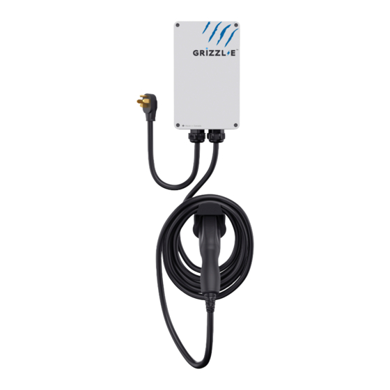
1. Introduction & Unpacking 1.1 Your Charger Charger Components 1. Input Cable NEMA 14-50P or NEMA 6-50 2. Output Cable J1772 Connector 3. Latch Release Button 4. Indicator Light... -
Page 9: Package Contents
1.2 Package Contents Mounting Kit Front Plate Screw (x4) Back Plate Screws (x2) Security Pin (x1) Mounting Bracket (x1) EasyEvPlug Holster Holster Holster Screws (x4) Anchor (x4) Holster (x1) -
Page 10: Installation Planning And Service Wiring
2. Installation Planning and Service Wiring: WARNING: Disconnect the power supply to the charging station before installing, adjusting, or repairing the charging. Failure to do so may result in physical injury or damage to the power supply system and the charging station. CAUTION: To reduce the risk of fire, connect only to a circuit provided with the minimum branch circuit overcurrent protection requirements in accordance with the National Electrical Code ANSI/... -
Page 11: Adjustable Maximum Current Output
3. Adjustable Maximum Current Output The GRIZZL-E ™ charging station features the ability to adjust the maximum Charging Station current output to support 50A, 40A, 30A, or 20A Dedicated Circuit ratings as follows: Circuit Rating Maximum Charging Station Output 40A (9.6 kW) 32A (7.68 kW) 24A (5.76 kW) 16A (3.84 kW) - Page 12 3. With the front cover placed to the side, locate the DIP switch on the charging station circuit board. The DIP switch is a 4-position switch on the main circuit board, located directly to the left of the LED. DOWN WARNING: Do not touch live electrical parts.
- Page 13 4. Adjust the Maximum Current Output to either 40A, 32A, 24A or 16A, using the following combination of DIP switch settings: Switch 3 Switch 4 DIP Switch Setting Maximum Current Output Switch 1 Switch 2 40A Maximum Current Output DOWN (Factory Default Setting) DOWN DOWN...
-
Page 14: Installation
4. Installation 4.1 Tools & Parts Required for Installation Prior to mounting, determine the location of an acceptable mounting support. All charging station products must be anchored into a mounting support such as a 2” x 4” stud or a solid concrete wall. -
Page 15: Install The Charging Station
4.2 Install the Charging Station 1. Separate the front and back piece of the mounting bracket by pushing down on the notch. Back Piece Front Piece 2. Attach the front piece of the mounting bracket to the back of the charging station using the Front Plate screws. - Page 16 3. Secure the back piece of the mounting bracket to the wall or other suitable structure using the Back Plate screws. The back piece of the mounting bracket has 3 holes to support attachment to various surfaces. Use the top two holes to attach the mounting bracket to a wall stud. Mounting Screw Recommendations: •...
- Page 17 4. Mount the charger on the wall by securing the front piece of the mounting bracket to the back piece of the mounting bracket. 5. Secure the charger in place by inserting either the security pin or the outdoor security lock into the mounting bracket.
-
Page 18: Wiring Connection
5. Wiring Connection 5.1 Optional Hardwire Connection 1. Choose the appropriate conduit in accordance with all applicable, local, and electrical safety codes and standards. The connection into the enclosure is 1.3 inches in diameter. 2. Using the appropriate tool, clamp the ring wire terminal to the copper wire. For non- insulated terminals, use heat shrink tube to cover the non-insulated portion of the terminal. - Page 19 CAUTION: To reduce the risk of fire, connect only to a circuit provided with the appropriate amperes minimum branch circuit overcurrent protection in accordance with the National Electrical Code, ANSI/NFPA 70, and the Canadian Electrical Code, Part I, C22.1. 8. Once the input wiring and conduit are connected, reassemble the charging station. Reinstall the charging station font cover using the following torque force to secure the (4) screws: Screw...
-
Page 20: Replace Output Cable
5.2 Replace Output Cable 1. Remove the front cover by removing the 4 screws at each corner of the charging station. 2. Loosen the gland beneath the charger. 3. Loosen strain relief clamp on inside of charger. Use a screwdriver or other tool to break metal clamp. -
Page 21: Easyevplug Holster And Cable Management System
6. EasyEvPlug Holster and Cable Management System The EasyEVPlug™ Holster or Tesla EasyEVPlug™ Holster is the new innovative method to pro- tect your plug and manage your cord. It has the following features: • No need to aim – flawless plug even in the dark. •... -
Page 22: Charging Status Indicators And Buzzers
7. Charging Status Indicators and Buzzers 7.1 Indicator Lights Grizzl-E uses the following indicator lights for the charger status: LED Indicator Buzzer Description Definition No buzzer Not illuminated Power Off Blue Steady Ready No buzzer No buzzer Blue Flashing Vehicle detected No buzzer Green Flashing Charging in progress... -
Page 23: Self-Monitoring And Recovery (Auto Restart)
4. With the circuit breaker in the “OFF” position, wait 1-2 minutes and then switch the upstream circuit breaker back to the “ON” position 5. Confirm the Fault light is no longer present. 6. If the Fault light remains, please contact United Chargers. Fill out the Technical Support Form. Indicate the number of red flashes. -
Page 24: Operation
8. Operation 8.1 Connect and Charge Insert the charging Connector into the EV and ensure the connector is fully seated/locked in place. Once complete, the charging session will begin. 8.2 Stop Charging 1. Press down on the latch release button. Ensure latch release button is fully compressed. 2. -
Page 25: General Product Care And Use Information
• If the power cable or the charging connector is damaged, turn off the charging station supply circuit breaker, do not use the charging station, and Contact United Chargers Customer Support for replacement parts. • When moving or lifting the unit, always grasp and carry by the charging station body. -
Page 26: Warranty And Return Policy
10. Warranty and Return Policy GRIZZL-E ™ EV Residential Charging Stations 3-Year or 5-Year Replacement Warranty. This warranty is extended by United Chargers to original purchasers of GRIZZL-E ™ EV Charging Stations. United Chargers warrants that this product is free from defects in materials years and free from defects in workmanship for the period specified in the warranty from the date of purchase.
Need help?
Do you have a question about the Grizzl-E Classic and is the answer not in the manual?
Questions and answers