United Chargers GRIZZL-E Classic / Avalanche Edition / Special Edition / Refurbished Manual
- User manual & installation manual (26 pages) ,
- User manual & installation manual (26 pages)
Advertisement
- 1 IMPORTANT SAFETY INSTRUCTIONS
- 2 Product Features
- 3 Product Specifications
- 4 Introduction & Unpacking
- 5 Installation Planning and Service Wiring
- 6 Adjustable Maximum Current Output
- 7 Installation
- 8 Input Wiring Connection (Optional Hardwire Connection)
- 9 EasyEvPlug Holster and Cable Management System
- 10 Charging Status Indicators and Buzzers
- 11 Operation
- 12 General Product Care and Use Information
- 13 Documents / Resources
IMPORTANT SAFETY INSTRUCTIONS
This document contains instructions and warnings that must be followed when installing and using the Grizzl-E Electric Vehicle Supply Equipment (EVSE). Before installing or using the EVSE, read this document including any WARNING and CAUTION symbols.
The Symbols Used Have the Following Meanings

Risk of personal injury
 Risk of fire

Risk of electric shock

Risk of damage to equipment
- This document provides instructions for the charging station and should not be used for any other product. Before installation or use of this product, review this manual carefully and consult with a licensed contractor, licensed electrician, or trained installation expert to ensure compliance with local building codes and safety standards.
- Consult a licensed electrician to ensure that you can safely install and use this product.
- Ensure that the materials used, and the installation procedures, follow local building codes and safety standards.
- The information provided in this manual in no way exempts the user of responsibility to follow all applicable codes or safety standards.
Basic precautions should always be followed when using electrical products, including the following:
- Read all the instructions before using this product.
- Children should not use this device.
- Do not put fingers into the EV connector.
- Do not touch live electrical parts.
- Do not use this product if the flexible power cord or EV cable is ragged, has broken insulation, or any other signs of damage.
- Do not use this product if the enclosure or the EV connector is broken, cracked, open, or shows any other indication of damage.
- Improper connection of the equipment grounding conductor can result in a risk of electric shock. Check with a licensed electrician if you are in doubt as to whether the product is properly connected and grounded.
Repair and Maintenance Clause
- All United Chargers products do not require routine maintenance however, periodic inspections should be conducted to ensure that all parts remain in good working order and no damage exists.
- Do not attempt to open, disassemble, repair, tamper with, or modify any components of the products. Contact United Chargers for any repairs.
This equipment is intended only for charging vehicles that do not require ventilation during charging. Please refer to your vehicle's owner's manual to determine ventilation requirements.
Product Features
GRIZZL-E™ Electric Vehicle Charging Station (EVSE)
- J1772 AC Level 2 (208-240 VAC), 40A Continuous Rated (9.6 kW)
- Adjustable Maximum Current Output (40A, 32A, 24A, 16A) to Support Multiple Circuit Ratings (50A, 40A, 30A, 20A)
- Extreme Duty, Rigid & Compact Design:
- Robust and heavy-duty aluminum cast case; airtight enclosure for indoor or outdoor use
- No user interface required with EVSE, simply Plug-in to your EV to initiate charging
- EasyEvPlug™ Holster or Tesla EasyEVPlug™ Holster with cable Management System.
- Plug-in Configuration for easy portability.
- Wall Mount with security features (including single stud mount), Pedestal, Bollard/Pole (Single & Dual Port) available from United Chargers.
- UL Listed.
Adjustable Maximum Current Output to Support Multiple Circuit Ratings
The GRIZZL-E™ Electric Vehicle Charging Station features the ability to adjust the maximum charging station current output to allow the use of a 50A, 40A, 30A, or 20A Dedicated Circuit as follows:
50A Circuit Rating: To support 40A (9.6kW) Maximum Charging Station Output
40A Circuit Rating: To support 32A (7.68kW) Maximum Charging Station Output
30A Circuit Rating: To support 24A (5.76kW) Maximum Charging Station Output
20A Circuit Rating: To support 16A (3.84kW) Maximum Charging Station Output
The Default Factory Setting is 40A (9.6kW). To change the maximum current output, refer to Chapter "Adjustable Maximum Current Output". If you are unsure of the circuit ratings in your home consult a licensed electrician.
Security and Tamper Feature
In addition to the security pin that secures the GRIZZL-E charging station to the wall mount bracket, the GRIZZL-E Classic can also be used with a coupler lock and key with a length of 90mm and diameter of 7mm
Product Specifications
United Chargers GRIZZL-E™ Electric Vehicle Charging Station (EVSE)
| Description | Specifications |
| Model Numbers | GR1-6-18-XX: GRIZZL-E™ EVSE, 18 ft. J1772 Cordset, Plug-in: NEMA 6-50 Plug GR1-6-24-XX: GRIZZL-E™ EVSE, 24 ft. J1772 Cordset, Plug-in: NEMA 6-50 Plug GR1-14-18-XX: GRIZZL-E™ EVSE, 18 ft. J1772 Cordset, Plug-in: NEMA 14-50 Plug GR1-14-24-XX: GRIZZL-E™ EVSE, 24 ft. J1772 Cordset, Plug-in: NEMA 14-50 Plug |
| EVSE Level | SAE J1772; AC Level 2 |
| Max Output Rating | 40A; 9.6 kW Maximum Output – For use with 50A Circuit Rating |
| Alternate Adjustable Output Ratings | 32A; 7.68 kW Maximum Output – For use with 40A Circuit Rating 24A; 5.76 kW Maximum Output – For use with 30A Circuit Rating 16A; 3.84 kW Maximum Output – For use with 20A Circuit Rating |
| Charge Cable Lengths | 18 ft. (5.5m) for GR1-6-18-XX and GR1-14-18-XX 24 ft. (7.2m) for GR1-6-24-XX and GR1-14-24-XX |
| Electrical Circuit/Input Power Requirements | Circuit Requirement: Dedicated Single Phase 208-240VAC, 50/60 Hz.; Branch Breaker: Double pole; Circuit Conductors: Line 1, Line 2, Earth/Ground |
| Input Power Connection | Standard: Plug-in, NEMA 6-50 or NEMA 14-50 Plug. Plug is removable for Hardwire Connection. |
| Installation Rating | NEMA 4, Indoor/Outdoor Rated |
| Operational Ratings | Temperature: -22⁰F to 122⁰F (-30⁰C to 50⁰C); Humidity: 95% RH non-condensing |
| Mounting | Wall or Pedestal Installation |
| Overall Dimensions | EVSE: 10.25 x 6.25 x 3.75 inches (26.0 x 16.0 x 9.3 cm) |
| Display & Indicators | LED Charge Status Indicators (Power/Ready, Charging, Fault) |
| Cable Management | EasyEvPlug™ with cable management |
| Standards & Compliance | UL certified |
Introduction & Unpacking
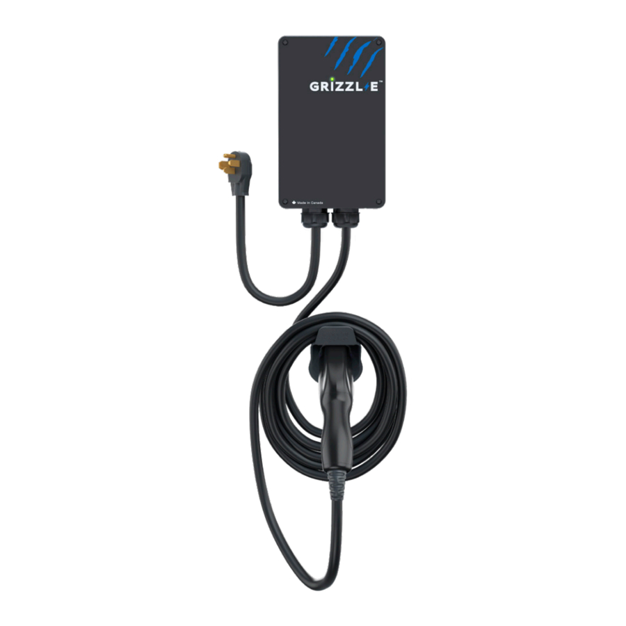
The Grizzl-E is a simple, powerful, heavy-duty, and portable electric vehicle charging station made in Canada and built to withstand the harshest conditions. Grizzl-E comes in three different varieties Classic Black, Avalanche White, or Extreme Camo.
Grizzl-E comes with either a 18ft or 24ft Premium or Regular cable. Internal design and components of the charger have been selected to provide maximum operational life of the device and be able to withstand the elements.
Grizzl-E provides up to 10 KW of power to your vehicle. Physical switches inside can be set to provide 16 Amps, 24 Amps, 32Amps or 40 Amps adjustable maximum current.
This user manual applies to the GRIZZL-E™ EVSE for Plug-in Hybrid Electric Vehicles (PHEVs) and Electric Vehicles (EVs).

Installation Planning and Service Wiring:
Disconnect the power supply to the charging station before installing, adjusting, or repairing the charging. Failure to do so may result in physical injury or damage to the power supply system and the charging station.
To reduce the risk of fire, connect only to a circuit provided with the minimum branch circuit overcurrent protection requirements in accordance with the National Electrical Code ANSI/ NFPA 7- and the Canadian Electrical Safety Code, Part 1, C22.1. If you are unsure if your circuit meets these requirements consult a licensed electrician.
Electrical Source Requirements
- Prior to mounting, locate an available electrical source that can support the following Input Requirements for the Charging Station Per local Electrical Safety Code requirements:
- 40A Maximum Output Setting (Default Factory Setting): a DEDICATED CIRCUIT rated for 50A; 208-240 VAC, 50-60 Hz, Single Phase must be used.
- 32A Maximum Output Setting (Optional Setting): a DEDICATED CIRCUIT rated for 40A; 208-240 VAC, 50-60 Hz, Single Phase must be used.
- 24A Maximum Output Setting (Optional Setting): a DEDICATED CIRCUIT rated for 30A; 208-240 VAC, 50-60 Hz, Single Phase must be used.
- 16A Maximum Output Setting (Optional Setting): a DEDICATED CIRCUIT rated for 20A; 208-240 VAC, 50-60 Hz, Single Phase must be used.
- A Double Pole Circuit Breaker of the circuit rating must be used.
- The Charging Unit has a built in GFCI protection; do not provide any additional GFCI protection upstream of the charging unit.
- The Charging Stations can connect a Standard NEMA 6-50 or 14-50 Receptacle, or the unit can be hardwired
Grounding Instructions
The charging station must be implemented equipment grounding through a permanent wiring system or an equipment grounding conductor. Use a cable with a dedicated grounding conductor connected to the equipment ground terminal block.
Adjustable Maximum Current Output
The GRIZZL-E ™ charging station features the ability to adjust the maximum Charging Station current output to support 50A, 40A, 30A, or 20A Dedicated Circuit ratings as follows:
| Circuit Rating | Maximum Charging Station Output |
| 50A | 40A (9.6 kW) |
| 40A | 32A (7.68 kW) |
| 30A | 24A (5.76 kW) |
| 20A | 16A (3.84 kW) |
- The Charging Station Default Factory Maximum Current Output Setting is 40A (9.6 kW) for use with a 50A Circuit Rating.
- The Circuit must be a DEDICATED CIRCUIT 208-240 VAC, 50-60 Hz, Single Phase.
- Requirements govern that only 80% of the circuit rated load may be utilized, hence the higher Circuit Ratings Requirement relative to maximum Charging Station output.
Adjust Maximum Current Output
To adjust the Maximum Current Output Setting:
- Ensure unit is unplugged. Place the Charging Station on a flat surface with the front cover facing up.
- Remove the front cover by removing the 4 screws at each corner of the charging station.
![]()

The LED pipe is attached to the front cover. When the front cover is removed, place it on a flat surface facing down to avoid damage to the LED pipe.
Generation 1 Grizzl-E (3 DIP Switches)
The Generation 1 Grizzl-E has 3 DIP switches located at the top left corner of the circuit board. If your Grizzl-E has 4 DIP Switches please see "Generation 2 Grizzl-E (4 DIP Switches)".
- With the front cover placed to the side, locate the DIP switch on the charging station circuit board. The DIP switch is a 3-position switch on the main circuit board, located directly to the left of the LED.
![]()
![]()
Do not touch live electrical parts. Disconnect the power supply to the charging station before adjusting the DIP Switches. Failure to do so may result in physical injury or damage to the power supply system and the charging station. - Using a non-conductive object adjust the Maximum Current Output to either 32A, 24A or 16A, using the following combination of DIP switch settings:
Maximum Current Output DIP 3 DIP 2 DIP 1 DIP Switch Setting (Picture) 40A Maximum Current Output
(Factory Default Setting)DOWN DOWN UP ![]()
32A Maximum Current Output UP DOWN UP ![]()
24A Maximum Current Output DOWN UP UP ![]()
16A Maximum Current Output UP UP UP ![]()
- Once the DIP Switch Setting is adjusted, reassemble the charging station. Reinstall the top cover to the charging station using the following torque force to secure the (4) socket cap screw:
Screw Torque M6 16 kgf-cm
13.88 lb-in


Generation 2 Grizzl-E (4 DIP Switches)
The Generation 2 Grizzl-E has 4 DIP switches located at the top left corner of the circuit board.
- With the front cover placed to the side, locate the DIP switch on the charging station circuit board. The DIP switch is a 4-position switch on the main circuit board, located directly to the left of the LED.
![]()
![]()
Do not touch live electrical parts. Disconnect the power supply to the charging station before adjusting the DIP Switches. Failure to do so may result in physical injury or damage to the power supply system and the charging station. - Using a non-conductive object adjust the Maximum Current Output to either 32A, 24A or 16A, using the following combination of DIP switch settings:
Switch 1 Switch 2 Switch 3 Switch 4 40A Maximum Current Output
(Factory Default Setting)UP UP UP DOWN ![]()
32A Maximum Current Output UP DOWN UP DOWN ![]()
24A Maximum Current Output UP UP DOWN DOWN ![]()
16A Maximum Current Output UP DOWN DOWN DOWN ![]()
- Once the DIP Switch Setting is adjusted, reassemble the charging station. Reinstall the top cover to the charging station using the following torque force to secure the (4) socket cap screw:
Screw Torque M6 16 kgf-cm 13.88 lb-in


Installation
Tools & Parts Required for Installation
Prior to mounting, determine the location of an acceptable mounting support. All charging station products must be anchored into a mounting support such as a 2" x 4" stud or a solid concrete wall. DO NOT mount this unit directly to a stucco/drywall/wall board.
| Tool | Size | Source of Supply | Description |
| Mounting Bracket | 255 x148 x 36 mm | Included with Product | For mounting the charging station to the wall/structure |
| Socket cap screw (x4) | 5/16" | Included with Product | For securing the charging station to the Mounting Bracket |
| Robertson-Head Screw (x2) | #14 | Included with Product | For installing the Mounting Bracket to the wall/structure |
| Holster/Tesla Holster | ™ 58 x 58 x 70 mm | Included with Product | To store the EV charging Plug and Cable |
| Phillips-Head Screw (x8) | #8 | Included with Product | For installing the EasyEvPlug™ to the wall/ structure |
| Anchors (x8) | #8 | Included with Product | For installing the EasyEvPlug™ to the wall/structure |
| Philips Screwdriver | PH3 | Commercially Available | For Holder Installation and Optional Hardwire Install |
| Allen key | M4 | Commercially Available | For Charging Station Cover Screws |
| Allen key | 3/16" | Commercially Available | For installing the enclosure plate to the back of the station body. |
Install the Charging Station
- Separate the front and back piece of the mounting bracket by pushing down on the notch.

- Attach the front piece of the mounting bracket to the back of the charging station using the Socket-cap screws. Ensure the top of the mounting bracket is matched with the top of the charging station.

- Secure the back piece of the mounting bracket to the wall or other suitable structure using the Robertson-head screws.
![]()
The back piece of the mounting bracket has 3 holes to support attachment to various surfaces. Use the top two holes to attach the mounting bracket to a wall stud.
Mounting Screw Recommendations:- For finished walls supported by wood studs, use #14 or M6 tapping screws. (Included).
- For masonry walls, use M6 mechanical screws. (Commercially available)
- Use following torque force:
Screw Torque M6 50 kgf-cm
43.4 lb-in1/4" 50 kgf-cm
43.4 lb-in


Mount the unit between 24 inches (0.6 m) and 60 inches (1.5m) from the ground. The charging station should not be more that 18 inches away from the NEMA outlet. The NEMA outlet should be located no less than 20~26" from the ground or as defined by applicable, local electrical safety codes and standards.
- Mount the charger on the wall by securing the front piece of the mounting bracket to the back piece of the mounting bracket.

- Secure the charger in place by inserting either the security pin or the outdoor security lock into the mounting bracket.
- Plug the power cord into the wall outlet.

Input Wiring Connection (Optional Hardwire Connection)
- Choose the appropriate conduit in accordance with all applicable, local, and electrical safety codes and standards.
![]()
- Using the appropriate tool, clamp the wire terminal to the copper wire. For non-insulated terminals, use heat shrink tube to cover the non-insulated portion of the terminal.
![]()
- Remove the front cover by removing the 4 screws at each corner of the charging station. For more information on how to remove the front cover refer to Chapter "Adjust Maximum Current Output".
- With the front cover placed to the side, use Philips screwdriver to release terminal screws of the input cable. Loosen the Strain Relief Fitting for the 6-50 or 14-50 Plug and Remove the Plug. Remove the Strain Relief connector.
- Insert the wire end passing through the conduit and insert them into the input wiring hole. (Use Red wire for L1, Black wire for L2, Green wire for G). Attach the copper wire on the corresponding terminal block. Use the following wire and torque force when connecting to input terminal block.
Model Terminal Conductor Screw Rating Torque GRIZZL-E™ L1, L2, G 8 AWG M4 90C, copper wire 16 kgf-cm
13.88 lb-in


To reduce the risk of fire, connect only to a circuit provided with the appropriate amperes minimum branch circuit overcurrent protection in accordance with the National Electrical Code, ANSI/NFPA 70, and the Canadian Electrical Code, Part I, C22.1.
- Once the input wiring and conduit are connected, reassemble the charging station. Reinstall the charging station font cover using the following torque force to secure the (4) screws:
Screw Torque M4 16 kgf-cm
13.88 lb-in
EasyEvPlug Holster and Cable Management System
The EasyEVPlug™ Holster or Tesla EasyEVPlug™ Holster is the new innovative method to protect your plug and manage your cord. It has the following features:
- No need to aim – flawless plug even in the dark.
- Your EV holster will always be in a convenient location.
- Saves space – special angle for less wall clearance.
- Integrated cable management – holds up to 25 feet of cable.
The EasyEvPlug holster can be installed at any location near the charging station.
- Hold back of holster against the mounting surface. Fasten Phillips head screws through back holes. Use anchors if attaching directly to drywall.
![]()
- Insert charging connector into holster.
![]()
- Wrap cable on top of EasyEvPlug.
![]()


Charging Status Indicators and Buzzers
Indicator Lights
Grizzl-E uses the following indicator lights for the charger status:
| LED Indicator | Buzzer | Description | Definition |
 | No buzzer | Not illuminated | Power Off |
 | No buzzer | White | Initialization |
 | No buzzer | Blue Steady | Ready |
 | No buzzer | Blue Flashing | Vehicle detected |
 | No buzzer | Green Flashing | Charging in progress |
 | No buzzer | Green Steady | Charging complete or no current consumed by the car |
 | Buzzer beeps | Red Flashing* | Fault |
*See Chapter "LED Fault Indicator" to identify the type of fault.
LED Fault Indicator
The number of red flashes shows the type of fault:
| LED Indicator | # of Flashes | Error Description |
| Red Flashing | 1 | Lost ground - AC Line1 |
| Red Flashing | 2 | GFCI High Leakage |
| Red Flashing | 3 | Relay is stuck |
| Red Flashing | 4 | GFCI Low Leakage |
| Red Flashing | 5 | High temperature of the module |
| Red Flashing | 6 | High temperature of the relay- |
| Red Flashing | 7 | Pilot state is Status E |
| Red Flashing | 8 | Pilot state is Status F |
| Red Flashing | 9 | Diode error |
| Red Flashing | 10 | Over Current |
| Red Flashing | 12 | Application Error |
Reset Charger
In the instance of a fault, it is recommended that you perform a reset:
- Count the number of flashes as described above and record the error type.
- Unplug the charging Connector from your EV
- Turn off the power to the Charging Station by switching the upstream circuit breaker to the "OFF" position
- With the circuit breaker in the "OFF" position, wait 1-2 minutes and then switch the upstream circuit breaker back to the "ON" position
- Confirm the Fault light is no longer present.
- If the Fault light remains, please contact United Chargers. Download the Technical Support Form and send an email to techsupport@unitedchargers.com. Indicate the number of red flashes.
Operation
Connect and Charge
Insert the charging Connector into the EV and ensure the connector is fully seated/locked in place. Once complete, the charging session will begin.

Stop Charging
- Unplug the charging station by pressing the connector button and removing the Charger Connector from the EV (once the connector button is depressed, the charging session terminates immediately).
- Return the connector to the holster.
General Product Care and Use Information
The exterior of the charging station is designed to be waterproof and dust proof (NEMA 4 Outdoor Rated). However, periodic cleaning may be required, depending on local conditions. To ensure proper maintenance of the charging station, follow these guidelines:
- To avoid damaging the finish of the products, only use an automotive grade soft cleaning cloth with soap and water to remove accumulated dirt and dust. Do not use cleaning solvents to clean any of the product components.
- Despite the water resistance of the enclosure, submerging the unit in water is not recommended.
- Ensure the charging connector is put back in the holster after charging to avoid damage.
- Ensure the power cable is stored on the charging station after use to avoid damage.
- If the power cable or the charging connector is damaged, turn off the charging station supply circuit breaker, do not use the charging station, and Contact United Chargers Customer Support for replacement parts.
- When moving or lifting the unit, always grasp and carry by the charging station body. Never attempt to lift, move, or carry the unit by any of the electrical cables. Improper handling may cause damage to the unit.
Download the Technical Support Form: https://grizzl-e.com/wp-content/uploads/2021/03/United-Chargers-Technical-Support-Form.pdf
And Send it to: info@unitedchargers.com
United Chargers Inc
90 Gough Road, Unit 2
Markham, Ontario L3R 5V5 Canada
Phone: +1-833-840-4970
E-mail: info@unitedchargers.com
Website: www.grizzl-e.com
Documents / Resources
References
Download manual
Here you can download full pdf version of manual, it may contain additional safety instructions, warranty information, FCC rules, etc.
Download United Chargers GRIZZL-E Classic / Avalanche Edition / Special Edition / Refurbished Manual
Advertisement


Need help?
Do you have a question about the GRIZZL-E Classic and is the answer not in the manual?
Questions and answers