Table of Contents
Advertisement
Quick Links
Advertisement
Table of Contents

Related Manuals for MIR 250 Hook


Summary of Contents for MIR 250 Hook
- Page 1 User Guide (en) Date: 01/2023 Revision: v.1.2...
-
Page 2: Copyright And Disclaimer
Copyright and disclaimer Copyright and disclaimer Mobile Industrial Robots A/S (MiR) makes no warranties, expressed or implied, in respect of this document or its contents. In addition, the contents of this document are subject to change without prior notice. Every precaution has been taken in the preparation of this document. -
Page 3: Table Of Contents
1.1 Where to find more information 1.2 Version history 2. Product presentation 2.1 Main features of MiR250 Hook 2.2 External parts 2.3 Internal parts 2.4 How MiR Hook 250 works 3. Warranty 4. Safety 4.1 Safety message types 4.2 General safety precautions 4.3 Intended use 4.4 Users... - Page 4 Table of contents 6.1 In the box 6.2 Unpacking MiR250 Hook 6.3 Connecting the battery 6.4 Powering up the robot 6.5 Connecting to the robot interface 6.6 Driving the robot in Manual mode 6.7 Moving the robot by hand 6.8 Checking the robot 6.9 Mounting the nameplate 6.10 Enable the MiR250 Hook feature 6.11 Testing the top module...
- Page 5 11.1 System overview 11.2 Personnel detection 11.3 Overspeed avoidance 11.4 Stability 11.5 Emergency stop buttons 11.6 MiR Hook 250 safety functions 11.7 Safety stop 11.8 Light indicators and speakers 12. Commissioning 12.1 Analysis of the work environment 12.2 Risk assessment 12.3 Cart specifications...
- Page 6 Table of contents 13.3 Creating a cart 13.4 Creating the mission Prompt user 13.5 Creating the mission Try/Catch 13.6 Creating the mission Variable docking 13.7 Creating a cart mission 13.8 Testing a mission 14. Demounting the top module 15. Maintenance 15.1 Regular weekly checks and maintenance tasks 15.2 Regular checks and replacements 15.3 Battery maintenance...
-
Page 7: About This Document
Documentation: • Quick starts describe how you start operating MiR robots quickly. It comes in print in the box with the robots. Quick starts are available in multiple languages. • User guides provide all the information you need to operate and maintain MiR robots and how to set up and use top modules and accessories, such as charging stations, hooks, shelf lifts, and pallet lifts. -
Page 8: Version History
MiR products. • Troubleshooting guides can help you determine the cause of an issue you are experiencing with your MiR product and how to resolve it. 1.2 Version history This table shows current and previous versions of this document. - Page 9 Added description about Fast docking. Affects section: Markers • Updated copyright. • Updated reference to robot or MiR Fleet reference guide to interface guide. • Updated style. MiR250 Hook User Guide (en) 01/2023 - v.1.2 ©Copyright 2021-2023: Mobile Industrial Robots A/S.
- Page 10 Added information about wheel wear down tolerance. Affects section: Maintenance. • Added information about how the robot picks up and places carts. Affect section: How MiR Hook 250 works. • General improvements throughout the manual. MiR250 Hook User Guide (en) 01/2023 - v.1.2 ©Copyright 2021-2023: Mobile Industrial Robots A/S.
- Page 11 1. About this document Revision Description Date: 2021-06-15 Robot HW: 1.0 Top module HW: 1.0 • First edition MiR250 Hook User Guide (en) 01/2023 - v.1.2 ©Copyright 2021-2023: Mobile Industrial Robots A/S.
-
Page 12: Product Presentation
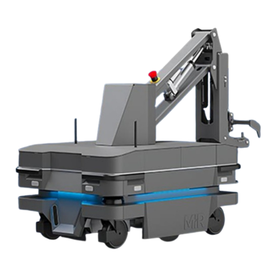
MiR250 Hook is a MiR250 robot with a MiR Hook 250 top module mounted to it. It is designed to transport carts indoors within production facilities, warehouses, and other industrial locations where access to the public is restricted. -
Page 13: Main Features Of Mir250 Hook
MiR250 Hook transports carts that are designed according to the specifications in "Cart specifications" on page 139. Specifications for MiR250 Hook are available on the MiR website. 2.1 Main features of MiR250 Hook The main features of MiR250 Hook are: •... - Page 14 MiR Charge 48V These fully automatic chargers enable MiR robots to recharge their batteries. Together with MiR Fleet, charging of robots can be fully automated, ensuring that robots never run out of power during missions. MiR250 Hook User Guide (en) 01/2023 - v.1.2 ©Copyright 2021-2023: Mobile Industrial Robots A/S.
-
Page 15: External Parts
2. Product presentation 2.2 External parts This section presents the parts of MiR250 Hook that are visible on the outside. Figure 2.1 MiR250 Hook external parts. Table 2.1 Identification of the external parts in Figure 2.1 Pos. Description Pos. Description Hook center cover Corner bumper: four pcs, one on each corner... - Page 16 2. Product presentation Pos. Description Pos. Description 3D depth camera: two Nanoscan3 safety laser pcs, both in the front— scanner: two pcs, in "Obstacle detection opposite corners—see " on page 106 "Obstacle detection " on page 106 Status light: on all four Side cover: opens to side sides of the robot—see compartment—see...
- Page 17 Identification label MiR250 Hook is delivered with identification labels mounted to both the MiR250 robot and the MiR Hook 250 top module. The identification labels identify the product, the product serial number, and the hardware version of the product. Figure 2.2 The identification label of MiR250 is located on the rear cover next to the battery.
- Page 18 2. Product presentation Figure 2.3 The identification label of MiR Hook 250 is located on the center back of the hook base frame. Figure 2.4 Example of a MiR250 Hook identification label. Item number : 800257 Product serial number : ...
- Page 19 2. Product presentation Rated drawbar pull : Model : MiR250 Hook Coupling height : 80–350 mm S/N : 103103001 This device complies with part of the FCC Rules. Operation is subject to the following two conditions: (1) Year of construction : 2023 This device may not cause harmful interference, and (2) Made in Denmark this device must accept any interference received, Lithium ion battery...
- Page 20 2. Product presentation Color indication: • Red: It is possible to engage the Manual stop. Resume button Pressing this button: • Clears the Emergency or Protective stop state. • Lets the robot continue operating after the Manual stop button was pressed or after the operating mode changes.
- Page 21 2. Product presentation For more information on operating modes, see "Operating modes" on the next page. Remove the Operating mode key during normal operation. The vibrations from the robot's driving may shake the key and plug, and can cause an unwanted Protective stop.
- Page 22 2. Product presentation Figure 2.8 Turn the Manual brake release switch clockwise to release the brakes. The mechanical brakes require electrical power to be released. To release the brakes, the robot must be connected to an active and charged battery when you turn the switch. When the robot is driving, the robot engages and releases the mechanical brakes automatically.
-
Page 23: Internal Parts
2. Product presentation 2.3 Internal parts Most internal parts of MiR250 Hook are accessed through covers that open to different compartments: • Front compartment • Rear compartment • Side compartments • Top compartments To access the compartments correctly, see " Accessing the internal parts" on page 50. - Page 24 2. Product presentation Figure 2.9 Internal parts of the front compartment. Table 2.3 Identification of internal parts in Figure 2.9 Pos. Description Pos. Description Robot computer Carrier board with motor controller controlling the right-side drivetrain Loudspeaker Charging pads under robot and broom for keeping dirt away from the charging pads 3D cameras...
- Page 25 2. Product presentation Rear compartment The rear compartment components are listed in Table 2.4. NOTICE The unique nameplate of your robot is to be mounted on the rear compartment cover—see "Mounting the nameplate" on page 79. Make sure you do not swap the cover with covers from other robots.
- Page 26 2. Product presentation Pos. Description Pos. Description Battery lever Power board for motor controllers, robot computer, and safety Safety PLC Cable charging interface Side compartments The left side compartment components are listed in Table 2.5 Figure 2.11 Internal parts of the left side compartment. Table 2.5 Identification of internal parts in Figure 2.11 Pos.
- Page 27 2. Product presentation Pos. Description Pos. Description Safe Torque Off (STO) contactor Bogie and drivetrain consisting of motor, gearbox, encoder, brake, drive wheel, and assembly parts The right side compartment components are listed in Table 2.6 Figure 2.12 Internal parts of the right side compartment. Table 2.6 Identification of internal parts in Figure 2.12 Pos.
- Page 28 2. Product presentation Top compartments The two top compartments contain electrical interfaces that can be connected to top modules. The top compartments are only accessible after the top module has been removed— "Demounting the top module" on page 231. Figure 2.13 The top compartments on the robot. Table 2.7 Identification of top compartments in Figure 2.13 Pos.
- Page 29 General purpose inputs General purpose outputs Auxiliary safety functions I/Os Auxiliary safety functions I/Os MiR Hook 250 The components of MiR Hook 250 are listed in Table 2.9. MiR250 Hook User Guide (en) 01/2023 - v.1.2 ©Copyright 2021-2023: Mobile Industrial Robots A/S.
- Page 30 2. Product presentation Figure 2.15 Internal parts in MiR Hook 250. Table 2.9 Identification of internal parts in Figure 2.15 Pos. Description Pos. Description Motor controllers Emergency stop Brake Ethernet interface Auxiliary power connector Emergency stop interface interface Counterweight: three pcs Hook computer...
-
Page 31: How Mir Hook 250 Works
MiR Hook 250 is connected to MiR250 through the Ethernet, Power, and Auxiliary emergency stop interfaces. If any of these connections are disconnected, MiR Hook 250 is not able to operate. The robot uses Cart position to identify places where it can pick up and place carts—see "Positions"... - Page 32 2. Product presentation Picking up carts The following steps describe how the robot picks up a cart at a Cart position: The robot moves to the Pick up Entry position in front of the Cart position. The center of the Entry position is 1.30 m from the center of the Cart position. The robot turns around and orients itself so the hook camera is able to read the ID tag on the cart.
- Page 33 2. Product presentation Driving with a cart Once a cart is attached to MiR250 Hook, the robot does not reverse when driving to another position. As a result, its dynamic obstacle avoidance capabilities are somewhat restricted compared to when a cart is not attached. The system operator needs to keep this in mind when choosing where to run the robot.
- Page 34 2. Product presentation The robot opens its gripper, lowers the hook arm, and drives forward, leaving the cart at the Cart position. Reverse If the Cart position is placed so the back is against a structure or other obstacle, the robot must place the cart in reverse.
- Page 35 2. Product presentation The following steps describe how the robot reverses and places a cart at a Cart position in reverse: The robot moves to an Entry position of the Cart position. Depending on whether the robot approaches from the left or the right it will move to either of the following Entry positions: ...
- Page 36 2. Product presentation The robot pivots approximately 90° towards the Cart position. The robot now drives in reverse with the cart so the cart is parallel to the direction of the Cart position. The robot straightens up, and reverses with the cart into the Cart position. When reversing with a cart, the robot will warn with both a loud beeping sound and a flashing orange light.
- Page 37 2. Product presentation • Fast: The robot uses the most space in front on the Cart position, but less space to the sides, and places the cart faster than when using the other methods. • Compact: The robot uses the least space in front on the Cart position, but more space to the sides, and places the cart slower than when using the other methods.
-
Page 38: Warranty
3. Warranty 3. Warranty Mobile Industrial Robots offers a standard warranty on all products. Contact your distributor to see the terms and extent of product coverage. NOTICE Mobile Industrial Robots disclaims any and all liability if MiR250 Hook or its accessories are damaged, changed, or modified in any way. -
Page 39: Safety
4. Safety 4. Safety Read the information in this section before powering up and operating MiR250 Hook. Pay particular attention to the safety instructions and warnings. NOTICE Mobile Industrial Robots disclaims any and all liability if MiR250 Hook or its accessories are damaged, changed, or modified in any way. - Page 40 4. Safety NOTICE Indicates important information, including situations that can result in damage to equipment or property. Tells you where you can find more information about the topic. MiR250 Hook User Guide (en) 01/2023 - v.1.2 ©Copyright 2021-2023: Mobile Industrial Robots A/S.
-
Page 41: General Safety Precautions
4. Safety 4.2 General safety precautions This section contains general safety precautions. CAUTION Harmful electromagnetic interference might be the result of having two radio modules transmitting at the same time. The robot is certified to have only one radio module active at any given time. •... - Page 42 Using a charging device different from the one supplied by the manufacturer can cause a fire and thereby burn injuries to nearby personnel and damage to the robot and equipment. • Only use an original MiR charger. MiR250 Hook User Guide (en) 01/2023 - v.1.2 ©Copyright 2021-2023: Mobile Industrial Robots A/S.
- Page 43 4. Safety WARNING Lithium battery packs may get hot, explode, or ignite and cause serious injury if they are misused electrically or mechanically. Observe the following precautions when handling and using lithium-ion batteries: • Do not short-circuit, recharge, or connect with false polarity. •...
- Page 44 4. Safety WARNING Load falling or robot overturning if the load on the robot is not positioned or fastened correctly can cause fall injuries to nearby personnel or damage to equipment. • Ensure that the load is positioned according to the specifications and is fastened correctly.
-
Page 45: Intended Use
MiR250 Hook is intended to be commissioned and used in indoor industrial environments where access for the public is restricted. For details about the environmental conditions in which MiR250 Hook should operate, see specifications for MiR250 Hook on the MiR website. MiR250 Hook is intended to be commissioned according to the guidelines in "Commissioning"... -
Page 46: Users
4. Safety The robot cannot detect objects between the robot and the cart, and it cannot detect objects behind the cart (the robot does not reverse as part of the route; however, it can reverse when placing a cart). For this reason, it is not possible to drive more than one cart at a time by chaining carts together. -
Page 47: Foreseeable Misuse
4. Safety Operators Operators have thorough knowledge of MiR250 Hook and of the safety precautions presented in this user guide. Operators have the following main tasks: • Servicing and maintaining MiR250 Hook. • Creating and changing missions and map features in the robot interface. Direct users Direct users are familiar with the safety precautions in this User Guide and have the following main tasks:... -
Page 48: Warning Label
4. Safety • Making the robot use a MiR Fleet controlled elevator while it is towing a cart • Using the robot in medical and life critical applications • Operating the robot outside the permissible operating parameters and environmental specifications •... - Page 49 4. Safety • You risk being crushed or trapped if you touch the robot while it is in motion. • You risk being crushed or trapped if the robot places a load outside a designated drop-off area due to faulty localization. •...
-
Page 50: Accessing The Internal Parts
The front and rear covers have to be removed before you can remove the side covers. For more information on how to remove the covers on MiR250, see the video How to remove and attach the covers on MiR250 on MiR Academy at the MiR website. CAUTION... - Page 51 5. Accessing the internal parts Loosen the bottom corners one at the time by pulling out each corner. Loosen the top corners one at the time by pulling each corner down, and then out. Pull off the cover. MiR250 Hook User Guide (en) 01/2023 - v.1.2 ©Copyright 2021-2023: Mobile Industrial Robots A/S.
-
Page 52: Rear Compartment
5. Accessing the internal parts 5.2 Rear compartment To open the rear compartment, follow these steps: Push the two white buttons on the rear cover at the same time. Loosen the bottom corners one at the time by pulling out each corner. MiR250 Hook User Guide (en) 01/2023 - v.1.2 ©Copyright 2021-2023: Mobile Industrial Robots A/S. -
Page 53: Side Compartments
5. Accessing the internal parts Loosen the top corners one at the time by pulling each corner down, and then out. Pull off the cover. 5.3 Side compartments To open a side compartment, follow these steps: Remove the front cover and rear cover—see "... - Page 54 5. Accessing the internal parts Turn the two screws counterclockwise with a T30 screwdriver. Loosen the bottom corners one at the time by pulling out each corner. Pull off the cover. MiR250 Hook User Guide (en) 01/2023 - v.1.2 ©Copyright 2021-2023: Mobile Industrial Robots A/S.
-
Page 55: Top Compartments
5. Accessing the internal parts 5.4 Top compartments The top compartments are only accessible after the top module has been removed— "Demounting the top module" on page 231. To open a top compartment, follow these steps: Unscrew and remove the antenna from the top cover. MiR250 Hook User Guide (en) 01/2023 - v.1.2 ©Copyright 2021-2023: Mobile Industrial Robots A/S. - Page 56 5. Accessing the internal parts Unscrew the nut from the antenna connector with a 10 mm wrench, and push the antenna cable free of the cover. NOTICE With the antenna cables mounted, the plastic top covers can be lifted 50 mm. If you do not need to remove the cover completely, you do not have to remove the antennas.
- Page 57 5. Accessing the internal parts Pull off the cover. MiR250 Hook User Guide (en) 01/2023 - v.1.2 ©Copyright 2021-2023: Mobile Industrial Robots A/S.
-
Page 58: Mir Hook
5. Accessing the internal parts 5.5 MiR Hook 250 To access the internal parts of MiR Hook 250, follow these steps: Remove the center cover by unscrewing the four screws (two on each side) with a T25 screwdriver and lifting the cover off. MiR250 Hook User Guide (en) 01/2023 - v.1.2 ©Copyright 2021-2023: Mobile Industrial Robots A/S. - Page 59 5. Accessing the internal parts Remove the antennas from the front cover. Remove the front and rear covers by lifting them slightly up and out. The covers are held in place with magnets. MiR250 Hook User Guide (en) 01/2023 - v.1.2 ©Copyright 2021-2023: Mobile Industrial Robots A/S.
- Page 60 5. Accessing the internal parts Remove the internal front and rear covers by unscrewing the eight screws (four in each cover) with a T25 screwdriver and lifting the covers off. MiR250 Hook User Guide (en) 01/2023 - v.1.2 ©Copyright 2021-2023: Mobile Industrial Robots A/S.
-
Page 61: Getting Started
6. Getting started 6. Getting started This section describes how to get started with MiR250 Hook. To be able to use MiR250 Hook, your robot must be running software version 2.11.0 or higher. Read "Safety" on page 39 before powering up MiR250 Hook. 6.1 In the box This section describes the contents of the MiR250 Hook box. -
Page 62: Unpacking Mir250 Hook
The USB flash drive in the document folder has the following content: • MiR250 Hook User Guide • MiR250 Hook Quick Start • MiR Network and WiFi Guide • MiR Cybersecurity Guide • MiR Robot Interface Guide • Getting the robot online •... - Page 63 6. Getting started Remove the lid from the box. Take the folder with the printed documents and the USB flash drive out of the box. MiR250 Hook User Guide (en) 01/2023 - v.1.2 ©Copyright 2021-2023: Mobile Industrial Robots A/S.
- Page 64 6. Getting started Remove four of the five walls of the box and the protective foam blocks. Remove the last wall of the box. MiR250 Hook User Guide (en) 01/2023 - v.1.2 ©Copyright 2021-2023: Mobile Industrial Robots A/S.
-
Page 65: Connecting The Battery
6. Getting started Place the lid of the box with the reinforcement face down so that you can use it as a ramp. Align the lid so that it is flush with the base of the box. 6.3 Connecting the battery To connect the battery to the robot, you need to open the rear compartment—see "... - Page 66 6. Getting started Pull up the lever to connect the battery connector to the battery. Turn the battery lever lock counterclockwise to lock the battery lever. MiR250 Hook User Guide (en) 01/2023 - v.1.2 ©Copyright 2021-2023: Mobile Industrial Robots A/S.
- Page 67 6. Getting started Reattach the rear cover by tilting it slightly so that the bottom points forward while inserting it into the two attachment sockets. Press the two white buttons while attaching the cover to the robot. Click the cover in place one corner at the time. MiR250 Hook User Guide (en) 01/2023 - v.1.2 ©Copyright 2021-2023: Mobile Industrial Robots A/S.
-
Page 68: Powering Up The Robot
6. Getting started 6.4 Powering up the robot To power up the robot, follow these steps: Press the Power button for three seconds to turn on the robot. The status lights waver orange, and the robot starts the software initialization process. When the initialization process ends, the robot goes into Protective stop. -
Page 69: Connecting To The Robot Interface
Press the Resume button to clear the Protective stop. The robot is now ready for operation. If you are not able to power up the robot upon delivery, see MiR 48V Battery Technical Guide to troubleshoot the issue. 6.5 Connecting to the robot interface When the robot is turned on, it enables the connection to its WiFi access point. - Page 70 MiR_20XXXXXXX. The access point name is derived from the robot application's model serial number. In a browser, go to the address mir.com and sign in. Switch to Manual mode, and drive the robot down the ramp—see "Driving the robot in Manual mode"...
-
Page 71: Driving The Robot In Manual Mode
6. Getting started 6.6 Driving the robot in Manual mode CAUTION When driving the robot in Manual mode, it is possible to mute the Protective fields and drive the robot into Forbidden zones and Unpreferred zones on the map. This means that the robot will not stop for physical objects and will not respond to zones on the map. - Page 72 6. Getting started On the robot, press the Resume button. The status lights turn blue, indicating that the Hook is in Manual mode. In the Hook menu, select Deactivate brake. Manually move the hook arm to approximately 0 degrees. MiR250 Hook User Guide (en) 01/2023 - v.1.2 ©Copyright 2021-2023: Mobile Industrial Robots A/S.
- Page 73 6. Getting started Select Activate brake. In the robot interface, select Manual control. MiR250 Hook User Guide (en) 01/2023 - v.1.2 ©Copyright 2021-2023: Mobile Industrial Robots A/S.
- Page 74 6. Getting started Select Manual control. The Resume button on the robot starts blinking. On the robot, press the Resume button. The status lights turn blue, indicating that the robot is in Manual mode. Drive the robot onto the ramp using the joystick. Place your foot in front of the ramp while the robot drives on it to keep the ramp from slipping.
- Page 75 6. Getting started Place the bottom plate in continuation of the lid of the box. Ensure that the bottom plate is placed with approximately 0.20 m overlap. Drive the robot carefully down and off the bottom plate. Place your foot in front of the ramp while the robot drives on it to keep the ramp from slipping.
-
Page 76: Moving The Robot By Hand
6. Getting started 6.7 Moving the robot by hand You should generally avoid moving the robot by hand, as it can cause the robot to lose its localization. If the robot gets stuck near an obstacle and cannot be moved by manual control, it might be the only option to move the robot by hand. -
Page 77: Checking The Robot
6. Getting started NOTICE When handling the robot, do not push or pull the robot sideways, and do not use the covers for pushing or pulling. Only use the designated pull handles, corner bumper, or the top module. 6.8 Checking the robot To ensure the robot is ready for use, check the following: ... - Page 78 6. Getting started • Check that your robot is running the latest recommended software. This also applies to newly supplied robots, as there may have been important software updates during the storage time and shipment of the robot. You can see the software version your robot is running in the bottom left corner of the robot interface.
-
Page 79: Mounting The Nameplate
6.9 Mounting the nameplate Before using MiR250 Hook, you must mount its unique nameplate to it. The nameplate contains information specific to your MiR application—see "Nameplate" on page 18. MiR250 Hook User Guide (en) 01/2023 - v.1.2 ©Copyright 2021-2023: Mobile Industrial Robots A/S. - Page 80 6. Getting started To mount the nameplate correctly, follow these steps: Locate the rear cover—see "External parts" on page 15. Clean the area marked in the image below with a degreasing agent. Mount the nameplate on the cleaned area. MiR250 Hook User Guide (en) 01/2023 - v.1.2 ©Copyright 2021-2023: Mobile Industrial Robots A/S.
-
Page 81: Enable The Mir250 Hook Feature
6. Getting started 6.10 Enable the MiR250 Hook feature To access the MiR250 Hook settings and mission menus, the MiR250 Hook features must be enabled. To check that they are enabled, follow these steps: Sign in to the robot interface, and go to System > Settings > Features. MiR250 Hook User Guide (en) 01/2023 - v.1.2 ©Copyright 2021-2023: Mobile Industrial Robots A/S. -
Page 82: Testing The Top Module
6. Getting started Under Hook, check that True is selected. 6.11 Testing the top module To test that the top module of MiR250 Hook is configured and connected correctly, follow the steps in the following sections. MiR250 Hook User Guide (en) 01/2023 - v.1.2 ©Copyright 2021-2023: Mobile Industrial Robots A/S. - Page 83 6. Getting started Activate Manual control Manual control must be activated before the hook can be moved manually. To activate Manual control, follow these steps: On the robot, turn the Operating mode key to Manual mode (turn it to the right). In the robot interface, go to Hook >...
- Page 84 6. Getting started The Manual control hook menu now appears in the robot interface. Manual test Under Hook > Manual control, select the following listed actions, and verify that the hook performs as described: • Open/Close: These actions open or close the hook gripper. MiR250 Hook User Guide (en) 01/2023 - v.1.2 ©Copyright 2021-2023: Mobile Industrial Robots A/S.
- Page 85 6. Getting started • Activate/Deactivate brake: These actions activate or deactivate the hook brake. The hook brake locks the hook arm and prevents it from turning horizontally.Activating the hook brake makes it easier to perform the cart calibration since even small hook movements may affect the calibration.
-
Page 86: Shutting Down The Robot
6. Getting started Manually push the arm close to 0 degrees. Select Activate brake. Homing is now complete. 6.12 Shutting down the robot To shut down MiR250 Hook, follow these steps: Ensure that the robot is not moving or executing an action. Press the Power button for three seconds. - Page 87 6. Getting started When the robot finishes the shutdown process, the status and signal lights go off. When you shut down the robot for transportation, service, or repair, the battery must be disconnected—see "Disconnecting the battery" on page 92. MiR250 Hook User Guide (en) 01/2023 - v.1.2 ©Copyright 2021-2023: Mobile Industrial Robots A/S.
-
Page 88: Storage
Charge the robot's battery before storage. • Store the robot in an area at room temperature with a non-condensing relative air humidity— see specifications on the MiR website. Temperatures and humidity below or above the specifications will shorten the service life of the battery. •... -
Page 89: Inactive Battery Modes
To activate the battery, you must either connect a 48V cable charger directly to the battery while the battery is disconnected from the robot, or you must connect MiR Cable Charger Lite 48V 3A to the robot's charging interface while the battery is connected to the robot. -
Page 90: Battery And Charging
80–90%. A MiR cable charger is not part of the MiR250 Hook standard delivery. Contact your distributor for more information. - Page 91 8. Battery and charging To charge MiR250 Hook using the cable charger, follow these steps: Plug the cable charger into an AC power supply. Always make sure to connect the cable charger to a power supply before connecting it to the battery. Overtime, the battery will take damage if you connect the charger to the battery before the power supply.
-
Page 92: Disconnecting The Battery
To disable Power save mode see "Storage" on page 88. For information about the charging time, see specifications on the MiR website. 8.2 Disconnecting the battery The battery can be disconnected for complete separation of all power to the robot. Disconnect the battery whenever the robot is to be transported, undergo maintenance, or stored for over 24 hours. -
Page 93: Enabling Fast Swap
8. Battery and charging Pull down the battery lever to disconnect the battery. Turn the battery lock counter-clockwise to lock the battery connector. 8.3 Enabling fast swap If you wish to enable the fast swap-option on the robot, you must first unscrew the plate holding these levers from the robot and then the levers themselves and fasten them to the levers controlling the connector. - Page 94 8. Battery and charging The levers holding the battery in place are fastened with screws from the factory to ensure that the battery stays disconnected during transportation. MiR250 Hook User Guide (en) 01/2023 - v.1.2 ©Copyright 2021-2023: Mobile Industrial Robots A/S.
- Page 95 8. Battery and charging The rear compartment holds the robot’s battery. To access the rear compartment, see " Accessing the internal parts" on page 50. MiR250 Hook User Guide (en) 01/2023 - v.1.2 ©Copyright 2021-2023: Mobile Industrial Robots A/S.
- Page 96 8. Battery and charging To enable the fast swap-option on the robot, follow these steps: Disconnect the battery—see "Disconnecting the battery" on page 92. Unscrew the two small screws mounting the status light bracket to the battery plate. Use a T20 screwdriver. Unscrew the two bolts and washers keeping the fast-swap levers raised.
-
Page 97: Swapping Out The Lithium-Ion Battery
8.4 Swapping out the lithium-ion battery MiR250 Hook is supplied with a removable lithium-ion battery. The battery can be charged inside the robot with a MiR cable charger. The robot is delivered with one lithium-ion battery. Contact your distributor if you need more batteries. - Page 98 8. Battery and charging The rear compartment holds the robot’s battery. To access the rear compartment, see " Accessing the internal parts" on page 50. To swap out the battery, follow these steps: Disconnect the battery—see "Disconnecting the battery" on page 92. Pull out the battery.
-
Page 99: Battery Disposal
8. Battery and charging 8.5 Battery disposal Legal obligations apply to used batteries. Used batteries must be recycled. Disposing used batteries in the household waste is prohibited. A recycling label indicates that the battery needs to be recycled and not disposed as municipal waste—see Figure 8.1 Contact your distributor to get specific information about their take back service. -
Page 100: Cybersecurity
We recommend conducting a cybersecurity risk assessment before commissioning MiR250 Hook. To ensure the cybersecurity of your MiR product, see MiR Cybersecurity Guide found on the USB drive shipped with MiR250 Hook and on the Support Portal. -
Page 101: Navigation And Guidance System
10. Navigation and guidance system 10. Navigation and guidance system The navigation and guidance system is responsible for driving the robot to a goal position while avoiding obstacles. This section describes the processes and components involved in the robot's navigation and guidance system. 10.1 System overview The purpose of the navigation and guidance system is to guide the robot from one position on a map to another position. -
Page 102: User Input
10. Navigation and guidance system Figure 10.1 Flow chart of the navigation and control system. The user provides the necessary input for the robot to generate a path to the goal position. The robot executes the steps in the navigation loop until it reaches the goal position and stops by engaging the brakes. -
Page 103: Global Planner
10. Navigation and guidance system • The current position of the robot on the map. This usually only needs to be provided when a new map is activated. Figure 10.2 On the map, the current position of the robot is identified by the robot icon , and the goal destination in this example is the robot position . - Page 104 10. Navigation and guidance system Figure 10.3 The global path is shown with the blue dotted line that leads from the start to the goal position. The global path is created only at the start of a move action or if the robot has failed to reach the goal position and needs to create a new path.
-
Page 105: Local Planner
10. Navigation and guidance system 10.4 Local planner The local planner is used continuously while the robot is driving to guide it around obstacles while still following the global path. Figure 10.5 The global path is indicated with the dotted blue line and is visible on the map. The local path is indicated with the blue arrow, showing the robot driving around a dynamic obstacle. -
Page 106: Obstacle Detection
10. Navigation and guidance system Once the local path is determined, the robot computer derives the desired rotational velocity of each drive wheel to make the robot follow the local path and sends the desired velocities for each motor to the motor controllers—see "Motor controller and motors"... - Page 107 10. Navigation and guidance system Safety laser scanners Two safety laser scanners, diagonally placed on one front and one rear corner of the robot, scan their surroundings. Each safety laser scanner has a 270° field of view, overlapping and thus providing a full 360°...
- Page 108 10. Navigation and guidance system Figure 10.7 The two safety laser scanners together provide a full 360° view around the robot. The laser scanners have the following limitations: • They can only detect objects that intersect a plane at 200 mm height from the floor. •...
- Page 109 10. Navigation and guidance system • From the floor plane, the robot does not detect objects below 30 mm from the ground. This value increases by 10 mm per meter from the robot—see Figure 10.9. The 3D cameras are only used for navigation. They are not part of the robot's safety system. CAUTION The 3D cameras cannot be used as a means for safety related risk reduction, for example, detecting low hanging obstacles.
- Page 110 10. Navigation and guidance system Figure 10.8 The two 3D cameras can see objects up to 1800 mm above floor height at a distance of 1200 mm in front of the robot and have a horizontal field of view of 114°. MiR250 Hook User Guide (en) 01/2023 - v.1.2 ©Copyright 2021-2023: Mobile Industrial Robots A/S.
- Page 111 10. Navigation and guidance system Figure 10.9 Objects below 30 mm from the ground are not detected by the camera. This value increases by 10 mm per meter from the robot. The 3D cameras have the following limitations: • They can only detect objects in front of the robot, unlike the full 360° view of the laser scanners.
- Page 112 10. Navigation and guidance system Figure 10.10 The proximity sensors in the corners of the robot detect objects below the safety laser scanners' plane of view. The main purpose of the proximity sensors is to detect low objects, such as pallets and forklift forks, placed close to the robot while it is standing still. When the robot begins to drive, it plans a path around the nearby detected obstacles.
- Page 113 10. Navigation and guidance system CAUTION Proximity sensors cannot be used as a means for safety related risk reduction, for example, detecting feet. They cannot be used as an alternative to the Personnel detection safety function—see "Personnel detection" on page 123. The robot may collide with and cause injury to personnel if you rely on the proximity sensors alone to detect personnel.
-
Page 114: Localization
10. Navigation and guidance system • When the robot is driving, obstacles detected by the proximity sensors are too close for the robot to stop or avoid. The robot relies on the laser scanners and 3D cameras to detect obstacles while it is driving. •... - Page 115 10. Navigation and guidance system Successful localization Failed localization When the robot can localize itself, it In a failed localization, the robot cannot determines a cluster of likely positions, determine a position where the red lines indicated in the images above as blue dots. (laser scanner data) align with the black lines on the map.
-
Page 116: Motor Controller And Motors
10. Navigation and guidance system • The robot must be able to detect the static landmarks that are marked on the map to be able to approximate its current position. Make sure there are not too many dynamic obstacles around the robot so that it cannot detect any static landmarks. Cannot detect any static landmarks Can detect enough static landmarks •... - Page 117 10. Navigation and guidance system Figure 10.11 The robot has reached the goal position and stops by engaging the dynamic brake function. Once the robot has stopped, the mechanical brakes are enabled. These brakes are used to keep the robot in place once it has stopped. You can compare the mechanical brakes with the parking brake or hand brake in a car.
-
Page 118: Safety-Related Functions And Interfaces
Emergency stop or Protective stop, depending on the function—see "Types of stop" below. For more information about how the safety-related electrical interfaces work without the MiR Hook 250 top module, see MiR250 User Guide. Types of stop There are four different stopped states: •... - Page 119 11. Safety-related functions and interfaces Protective stop The robot enters Protective stop automatically to ensure the safety of nearby personnel. When the robot enters Protective stop, internal safety contactors are switched so the robot's top module and all moving parts of the robot do not receive power. You can hear the safety contactors emit audible clicks when they are switched.
- Page 120 11. Safety-related functions and interfaces Figure 11.1 MiR250 Hook has one Emergency stop button located on the hook. CAUTION Emergency stop buttons are not designed for frequent use. If a button has been used too many times, it may fail to stop the robot in an emergency situation, and nearby personnel may be injured by electrical hazards or collision with moving parts.
- Page 121 If the limit is exceeded, the robot enters Protective stop. • Emergency stop buttons MiR Hook 250 has one Emergency stop button. When the button is pressed, the robot goes into Emergency stop. MiR250 Hook User Guide (en) 01/2023 - v.1.2 ©Copyright 2021-2023: Mobile Industrial Robots A/S.
- Page 122 11. Safety-related functions and interfaces • MiR Hook 250 safety functions MiR Hook 250 monitors the motor encoder data from the hook motors to ensure that the hook operates correctly. If the hook computer detects any discrepancies or errors in the hook components, it reports an error to the robot computer.
-
Page 123: Personnel Detection
11. Safety-related functions and interfaces 11.2 Personnel detection The Personnel detection safety function prevents the robot from colliding with personnel or obstacles by stopping it before it collides with any detected obstacles. It does this using the safety laser scanners. Clear ahead Obstacle detected The robot drives when the area is clear. - Page 124 11. Safety-related functions and interfaces Field set when driving forward The following table shows speeds and the field ranges when driving forward. The table describes the length of the Protective field in front of the robot in different cases. Each case is defined by a speed interval that the robot may operate at.
- Page 125 11. Safety-related functions and interfaces Field set when driving backward The field set for driving backward is the same as the field set for driving forward. However, the robot is limited to a top speed of 1.0 m/s when driving backward and therefore only has five fields.
- Page 126 11. Safety-related functions and interfaces Field sets to the sides The field sets on each side of MiR250 Dynamic varies with the speed of the robot. At speeds below 0.5 m/s, the field sets are very small, making it possible for the robot to traverse narrower corridors.
- Page 127 11. Safety-related functions and interfaces CAUTION Other risk reduction means must be implemented as muted Protective fields introduce a risk for collision with personnel in its path. • Areas where Protective fields are muted must be marked as Operating hazard zones, and personnel must be informed not to enter the zone while the robot is operating in it—see "Using operating hazard zones"...
-
Page 128: Overspeed Avoidance
11. Safety-related functions and interfaces You can mute the Protective field when driving the robot in Manual mode: Put the robot into Manual mode—see "Driving the robot in Manual mode" on page 71. In the robot interface, select Muted Protective fields in the joystick control. In the dialog box, select Yes to acknowledge the muting of the Protective fields. -
Page 129: Stability
11.6 MiR Hook 250 safety functions When MiR Hook 250 is mounted to MiR250, the electrical top interfaces are no longer accessible. MiR250 Hook User Guide (en) 01/2023 - v.1.2 ©Copyright 2021-2023: Mobile Industrial Robots A/S. -
Page 130: Safety Stop
11. Safety-related functions and interfaces The interfaces are used to communicate with the hook and connect to the Emergency stop button. Component monitoring The hook computer monitors the components within the hook to ensure they are operating correctly and the hook does not pose a risk to nearby personnel. If the hook computer detects any discrepancies or errors from the hook components, it relays this information to the robot computer via the Ethernet connection, and the robot enters Protective stop if the error indicates that the hook cannot be controlled reliably. -
Page 131: Light Indicators And Speakers
11. Safety-related functions and interfaces This can occur, for example, if the robot drives on surfaces that are not within specifications or the load on the robot does not fulfill the payload specifications. 11.8 Light indicators and speakers The robot uses its speaker and two types of light indicators to let people in the environment know what the robot is currently doing or planning to do. - Page 132 Waiting for Charging at MiR Fleet resource charging station or for another MiR robot to move When the robot's battery reaches a critically low level of power (0-1%), the ends of the status lights flash red. Signal lights Signal lights are used to indicate the robot’s immediate motion plans by signaling forwards- backwards-braking and left-right turns.
- Page 133 11. Safety-related functions and interfaces The signal lights work similarly to lights used on cars; white at the front, red at the back, and indicating a left or right turn by blinking. When the robot drives with muted Protective fields, for example, when docking to a charging station, all signal lights blink yellow.
- Page 134 11. Safety-related functions and interfaces CAUTION Unaware personnel may not see the robot in certain situations and risk colliding with the robot. This may result in injury to personnel or damage to equipment. • Make sure to adjust the volume of the robot's warning sounds so they are audible in the robot's work environment.
-
Page 135: Commissioning
It is the responsibility of the commissioner to: • Analyze the work environment. • Make a risk assessment of the full installation. • Procure carts with specifications supported by MiR. • Create and configure the site with maps. • Create missions. •... - Page 136 Temperature and humidity Temperatures outside of the approved temperature range can affect the performance and durability of the robot—see specifications on the MiR website. This is especially relevant for the robot's battery—see "Storage" on page 88.
- Page 137 Staging positions as parking areas. Evacuation plan In MiR Fleet, it is possible to set up evacuation of robots from one or more zones in case of an emergency situation. Evacuation zones should be created and Evacuation positions should be added to the map—see How to set up evacuation zones and fire alarms in MiRFleet for more...
-
Page 138: Risk Assessment
12. Commissioning information. 12.2 Risk assessment To achieve a safe installation, it is necessary to conduct a risk assessment of MiR250 Hook in the environment it will be used in. This is the responsibility of the commissioner. The risk assessment must cover both MiR250 Hook itself and also take into account carts, potential load transfer stations, work cells, and the work environment. -
Page 139: Cart Specifications
12. Commissioning MiR250 Hook as a partly completed machine As a partly complete machine, it is not known or determined by Mobile Industrial Robots how the application will be used. Adequate risk reduction measures and a risk assessment must be implemented prior to hand-over to the end user. - Page 140 12. Commissioning Figure 12.1 Front view of a cart (left), and side view of a cart (right). Table 12.1 Identification of the cart dimensions in Figure 12.1 Pos. Description Pos. Description Cart width: between 400 mm Cart length: between 500 and 1500 mm mm and 2400 mm Cart height: maximum 1800...
- Page 141 12. Commissioning Wheel configuration of the cart The carts must be fitted with two rigid and two swivel wheels. The two rigid wheels can either sit on the front or the back of the cart. Whether the robot performs better towing a cart with rigid wheels on the front or the back depends on the maneuvering conditions on the individual site and should be assessed before the gripper bar is fixed.
-
Page 142: Id Tags
12. Commissioning 12.4 ID tags A QR marker or an AprilTag is needed for MiR250 Hook to identify the individual carts. QR codes and AprilTags cannot be activated on the same site. QR markers The QR code contains the dimension of the marker and a unique name. The format is SizeUnit- Name. - Page 143 12. Commissioning It is recommended to use less than 17 characters in the QR code. For example, 75mm-Cart_A is 11 characters long. If more than 16 characters are added, the QR code will change format, and it will become more difficult to detect. AprilTags MiR250 Hook can be set to read AprilTags instead of QR codes.
-
Page 144: Calibrate Cart
12. Commissioning 12.5 Calibrate cart It is important to calibrate the relation between the robot and the cart. In the Manual control menu under Hook, enter values into the Change height field to define Entry and Lock heights for the hook to use when docking to and gripping a cart. When a value is entered and confirmed in Change height, the hook will move up or down depending on the chosen value. - Page 145 12. Commissioning Now enter a height which enables the hook to grip the bottom frame (gripper bar) without lifting or pushing the cart. This step may require some trial and error until you have the correct height. This height value is known as the Lock height, and is also used when defining the dimensions of the cart.
- Page 146 12. Commissioning Now attach the ID tag (QR-marker or AprilTag) to the cart so that the camera on MiR250 Hook can see it when MiR250 Hook is ready to grip the cart. NOTICE The ID tag must be oriented vertically when fixed on the cart grating. In other words, the ID tag must be facing the hook camera directly and may not be tilted in any direction.
-
Page 147: Creating And Configuring Maps
12. Commissioning 12.6 Creating and configuring maps The map is visible in the robot interface and is the basis for the robot's ability to navigate its surroundings safely and efficiently. The map illustrates the physical area in which the robot operates. - Page 148 If the robot must operate on different floors connected with ramps or elevators, you must have a map for each floor. • If you are using an elevator, ask your distributor for the guide How to set up elevators in MiR Fleet. •...
- Page 149 • End the mapping in the same place you started it. For more information on creating a map, see the Creating your first map-course in MiR Academy on the MiR website. Contact your distributor for access to MiR Academy. Cleaning up a map The robot navigates best when using a clean map with as little noise as possible.
- Page 150 12. Commissioning Figure 12.6 Example of a map that includes too much noise and dynamic obstacles. There are several tools in the robot interface that you can use to improve your map: • Use Erase uploaded or recorded data when editing walls to remove walls that were created around dynamic obstacles and noise on the map.
- Page 151 Use Draw a new line when editing walls to create solid and even walls. Checklist • You have created a map or several maps that cover the entire area you want the MiR robot to operate in. • You have removed all noise and dynamic obstacles from the map(s) and added floor everywhere the robot can travel to.
- Page 152 12. Commissioning All zones are ignored when you drive the robot in Manual mode or when you use a Relative move action (except when using Relative move actions in Limit-robots zones). NOTICE The robot prioritizes the instructions it receives in the following order: •...
- Page 153 12. Commissioning Highly dynamic areas A highly dynamic area is an area where objects are moved frequently. This could be a production area where pallets and boxes are often moved back and forth. Issue: The robot will stop if a person steps out in front of it. In a transient work flow area, the robot will stop and reassess its paths many times a day, thereby wasting valuable time.
- Page 154 12. Commissioning Doorways Going through narrow doorways can cause problems for the robot's global planner since the robot must drive closer to wall edges than it usually would. It can also be hazardous for the people working near the robot, as they might not see the robot coming. Issue: The robot does not plan its global path through narrow doorways, since this will bring the robot too close to a known obstacle.
- Page 155 12. Commissioning Shelves Shelves are often placed in a certain height above the floor on four (or more) posts and will often appear as dots on a map for the robot. This may cause the robot to believe that there is enough space (if the posts are far enough apart) below the shelves to pass through.
-
Page 156: Creating User Groups And Users
If there isn't enough space for robots to pass each other, you can use a Limit-robots zone to specify that only one robot may drive down the corridor at a time. To use Limit-robots zones, your robots must be connected to MiR Fleet. 12.7 Creating user groups and users All users of the robot must have a user profile in the system. - Page 157 • What functions or widgets should be available for the different users? For more details on users and dashboards, see MiR Robot Interface Guide on the Support Portal. Before creating users or user groups, you should map out the permissions for each user group...
-
Page 158: Markers
12. Commissioning Table 12.2 Example of user group mapping Integrator Commissioner Operator Direct user Maps Missions Settings Dashboards Sounds Checklist • You have mapped out the necessary permissions for each user group. • You have created the user groups in the user interface. •... - Page 159 12. Commissioning Docking to markers When robots position themselves at a set point relative to the marker, the robot must do a docking sequence. When the robot is docking, it uses its safety laser scanners to detect the marker and drives itself to the correct position relative to the detected marker. The robot begins docking to a marker from the marker's Entry position—see Figure 12.11.
- Page 160 12. Commissioning L-markers are the only markers where the Protective fields are not muted automatically. If you want the robot to mute the Protective fields while docking to an L-marker, you must use a Mute Protective fields action—see "Personnel detection" on page 123.
- Page 161 Figure 12.13 Illustration of how the robot Slow docks when the mission uses a Move action followed by Dock to action to the same marker. Undocking from markers A MiR robot can undock from markers automatically. When undocking, the robot reverses from the marker until it is outside of the undocking area—see Figure 12.14.
- Page 162 12. Commissioning Figure 12.14 The undocking area initiates an undocking sequence for any robots with their center in the zone before beginning an action (except Relative move actions). The red dot represents the center of the robot when it is docked to the marker, the blue dot represents how far back the robot intends to move to undock from the marker, and the blue area represents the undocking area.
- Page 163 12. Commissioning The undocking sequence will always occur if a robot begins an action where it plans a new route while inside the undocking area, even if the robot was not previously docked to the marker. This means the sequence is also initiated on robots that have entered the area via a Relative move action or Manual control.
- Page 164 Types of markers There are four standard marker types that all MiR robots can use: V, VL, L, and Bar-markers. A V-marker is a small, V-shaped marker that is designed for the robot to either dock to so its front or its rear is facing the marker.
- Page 165 12. Commissioning Figure 12.17 The icon used for VL-markers in the interface and an illustration of how robots can dock to the marker. An L-marker makes it possible for the robot to dock in several different ways and orientations. Robots can both dock to the inside and outside of an L-marker, and the marker can be on any side of the robot.
- Page 166 12. Commissioning A Bar-marker can be used for forward or reverse docking between two bars or plates, similar to pallet racks or shelves. Bar-markers must be between 400 mm and 2000 mm long, and the distance between the bars must be between 750 mm and 1500 mm. The robot can dock and undock from either end of the marker.
-
Page 167: Positions
There are different types of positions depending on whether the robot is part of a fleet or drives with top modules, but the standard position that is available in all MiR applications is the Robot position. This position has no special features, it simply marks a location where you want to be able to send the robot to. -
Page 168: Creating Missions
12.10 Creating missions MiR robots function through missions that you create. A mission is made up of actions, such as: move actions, logic actions, docking actions, and sounds, which can be put together to form a mission with as many actions as needed. - Page 169 12. Commissioning For more information on parameters and variables, see the guide How to use variables in missions. NOTICE The robot prioritizes the instructions it receives in the following order: • Instructions from zones. • Instructions from mission actions. • Instructions from system settings (except instructions from the setting Maximum allowed speed, which are never overruled by neither zones nor mission actions).
- Page 170 12. Commissioning To create efficient missions, you should first familiarize yourself with the available actions in MiR Robot Interface—see MiR Robot Interface Guide—and then consider: • Which tasks do I want the robot to perform? • Which actions are involved in this task and in which order are the actions executed? •...
- Page 171 For more information on building robust missions, see the Mission robustness videos in MiR Academy on the MiR website. Contact your distributor for access to MiR Academy. When you have figured out which tasks you want the robot to perform and how many different missions you need to create, you should consider how you want to organize the missions in different mission groups.
-
Page 172: Creating A Footprint
When a MiR robot is towing a cart, the footprint does not need to be increased. The robot will navigate with the cart using the dimensions provided in the cart type—see "Creating a cart "... - Page 173 12. Commissioning Default footprint Larger footprint The default footprint can be used when you If the robot's top moduel or load exceeds do not have a top module or load that the robot's physical dimensions, increase exceeds the robot's physical dimensions. the footprint size accordingly to ensure that the robot plans paths where the extended size is taken into account.
- Page 174 For a more thorough guide to creating footprints, see the guide How to change the robot footprint. For more information about the footprint editor, see MiR Robot Interface Guide. How Protective fields affect the footprint size Protective fields and footprints are both defined as areas relative to the robot that affect the robot's driving behavior.
- Page 175 12. Commissioning Physical dimensions: Adjust the length, width, and height of the footprint to match the physical footprint of the top module and its expected payload. Navigation: Adjust the length and width of the footprint to be as small as possible for both safe and agile autonomous driving.
- Page 176 12. Commissioning MiR250 Hook User Guide (en) 01/2023 - v.1.2 ©Copyright 2021-2023: Mobile Industrial Robots A/S.
-
Page 177: Using Operating Hazard Zones
12. Commissioning If you want to change what the robot's default footprint is, for example if the mounted top module is larger than the robot, go to System > Settings > Planner, and select a new footprint under Robot footprint. Checklist • You have created footprints that reflect all of the top module and loads the robot will carry. •... - Page 178 For the robot's space requirements, see the space requirements guide for your robot on the Support portal or see the specifications for your robot on the MiR website.
- Page 179 12. Commissioning Figure 12.23 The striped black and yellow line identifies the required operating hazard zone around the marker. The robot is placed on the Entry position to the marker. You must mark the floor area one meter around the docking marker and the robot when it is at the Entry position.
-
Page 180: Making A Brake Test
12. Commissioning When the robot begins the cart pick up or placement procedure, the status light band emits a wavering white light. Figure 12.24 The striped black and yellow line identifies the hazard zone around the back of the cart when it is placed. -
Page 181: Creating Dashboards
The decline of the surface the robot drives on Because of this, it is not possible to predetermine the exact braking distance of MiR robots. The distance has to be determined in the environment and under the driving conditions the robot will be operating in. - Page 182 12. Commissioning Figure 12.25 The default dashboard includes the robot information, a joystick for manual control, and the active map. When creating new dashboards, you should consider the following: • Who will be using the dashboards? • Which functionalities will they need to use the most? •...
-
Page 183: Updating Software
• Never turn off the robot during the update process. • If your robot has a MiR hook mounted to it, make sure to update the hook software before updating the robot software. • If your robot is connected to MiR Fleet, and your products are running software 2.12.0.4 or lower, make sure to remove the robot from MiR Fleet before updating them. -
Page 184: System Settings
12.17 System settings This section describes some of the commonly used system settings of MiR250 Hook that the commissioner must be aware of. Only the basic system settings are explained in this section—see MiR Robot Interface Guide for more information. NOTICE The robot prioritizes the instructions it receives in the following order: •... - Page 185 12. Commissioning Figure 12.26 Under System > Settings, there are several menus where you can edit your robot's settings. Remember to restart the robot if you have made any changes to the system settings. Planner In the Planner section, you set the basic parameters for driving the robot. This section refers to the local and global planner functions.
- Page 186 12. Commissioning Figure 12.27 You set basic parameters for driving the robot in the Planner section. Robot height defines the height of the robot including top modules. Use this setting if your robot operates permanently with a top module that makes the combined robot application higher than the robot itself.
- Page 187 12. Commissioning Max distance from path defines the maximum allowed distance in meters that the generated global path is allowed to deviate from the most direct path on the map. Max distance from path and Max distance from path with cart define the maximum allowed distance in meters that the generated global path is allowed to deviate from the most direct path on the map.
- Page 188 12. Commissioning Figure 12.28 Example of where the robot might benefit from using a Line-following configuration. When there isn't enough space for the robot to go around an obstacle, it will often spend more time trying to maneuver around the obstacle and correct its trajectory afterward than it would have just waiting for the obstacle to move out of the way.
- Page 189 12. Commissioning Figure 12.29 Change the parameters regarding docking to and from markers in the Docking section. In Undock from markers, you can select if the robot should undock from a marker before it starts moving from a docked position. It is usually best to set this setting to True to prevent the robot from going into Protective stop when moving away from markers.
- Page 190 12. Commissioning Safety system In the Safety system section, you can change which warning sound the robot should emit when it mutes its Protective fields and how loud the sound should play. Figure 12.30 In the Safety system section, you can change the robot's warning sound. Modify Muted protective fields sound to change the warning sound that is played when the robot drives with muted Protective fields.
- Page 191 12. Commissioning CAUTION Unaware personnel may not see the robot in certain situations and risk colliding with the robot. This may result in injury to personnel or damage to equipment. • Make sure to adjust the volume of the robot's warning sounds so they are audible in the robot's work environment.
- Page 192 This modifies how some of the pins in the electrical interfaces are used. Hook enables the hook feature. Enable this feature if your top module is a MiR Hook. This will enable the Hook menu in the robot interface.
- Page 193 Enable this feature if the robot drives with an application from Universal Robots. Fleet makes the robot visible for MiR Fleet. Enable this feature if the robot is part of a fleet. Modbus enables Modbus communications. When enabled, you can access the page System > Triggers to set up the Modbus triggers.
-
Page 194: Usage
13. Usage 13. Usage The main way to use MiR250 Hook is through missions that you create. In the following sections you will find practical examples of how missions can be tailored to different tasks. The examples include: • Setting markers and positions on the map. •... - Page 195 13. Usage Once the robot is localized, you can insert a marker on the map. In this example, we are using a VL-marker . To create a marker, follow these steps: Place your physical marker where you want the robot to dock. Manually drive the robot to the marker so the robot is facing the marker.
- Page 196 13. Usage Go to Setup > Maps, and select Edit for the active map. Within the editor, select Markers in the Object-type drop-down menu, and then select Draw new marker in the editor tools. MiR250 Hook User Guide (en) 01/2023 - v.1.2 ©Copyright 2021-2023: Mobile Industrial Robots A/S.
- Page 197 13. Usage In the Create marker dialog box, name the marker. Under Type, select your marker type. In this case, a VL-marker is used. Then select Detect marker. The X, Y, and orientation values will automatically be filled out with the current position of the robot.
- Page 198 13. Usage • To change where the robot stops relative to the marker, you can adjust the offsets. • The X-offset moves the robot closer to or further from the marker in meters. • The Y-offset moves the robot further to the left or right of the marker in meters. •...
-
Page 199: Creating Positions
13. Usage Select Save to create the marker. The marker is now visible on the map. You can make the robot dock to the marker by selecting it on the map and selecting Go to. The marker can also be used in missions. 13.2 Creating positions The following steps describe how to create a position on a map. - Page 200 13. Usage In the robot interface, go to the map editor of the map where you want to create a position. This is done by going to Setup > Maps and selecting Edit next to the map you would like to work on. In the Object-type drop-down menu, select Positions, and then select Draw a new position .
- Page 201 13. Usage Name the position. Under Type, select which type of position you want to make. In this example we are making a Robot position. Select OK to create the position. The position is now visible on the map. You can send the robot to the position by selecting it on the map and selecting Go to. The position can also be used in missions.
-
Page 202: Creating A Cart
13. Usage 13.3 Creating a cart Before creating missions with carts, you need to define the different carts that your robot will be docking to. This information is used when the robot is picking up, placing, and towing the cart to ensure that the cart is correctly transported. - Page 203 13. Usage Under Type, select Create / Edit. Here, you can either select an existing cart type, or create a new cart type by selecting Create type. When creating a new cart type, you must define the following parameters: • Name: Is used to identify the cart type. •...
- Page 204 13. Usage Figure 13.2 Front view of a cart (left), and side view of a cart (right). Table 13.1 Identification of the cart dimensions in Figure 13.2 Pos. Description Pos. Description Cart width: between 400 mm Cart length: between and 1500 mm 500 mm and 2400 Cart height: maximum 1800 Locked wheels...
- Page 205 13. Usage Under Calibration, select Create / Edit. Here you can either select an existing cart calibration, or create a new calibration by selecting Create calibration. When creating a new calibration you must defined the following parameters: • Name: Is used to identify the calibration settings. This will automatically be filled when you select Detect and MiR250 Hook is correctly positioned to read the ID tag of the cart.
-
Page 206: Creating The Mission Prompt User
13. Usage 13.4 Creating the mission Prompt user Prompt user actions are used for prompting the user with a question on how the robot should proceed. Prompt user is an example mission that uses a Prompt user action that lets you choose whether to send the robot to one position or another. - Page 207 13. Usage Select the following actions: • In the Logic menu, select Prompt user. • In the Move menu, select Move. • In the Move menu, select Move. The following steps describe which parameters each action should be set to. To modify the parameters, select the gearwheel at the right end of the action line to open the action dialog box.
- Page 208 13. Usage In the Prompt user action, set the parameters as follows: • Question: Enter the question Go to position one?. • User group: Select Users. • Timeout: Set the timeout to 10 minutes. In the Prompt user action, drag a Move to action under the Yes box and a Move to action under the No box.
- Page 209 13. Usage In the first Move to action, under Position, select No. position 1. MiR250 Hook User Guide (en) 01/2023 - v.1.2 ©Copyright 2021-2023: Mobile Industrial Robots A/S.
-
Page 210: Creating The Mission Try/Catch
13. Usage In the second Move to action, under Position, select p2. The mission should look like this: Select Save to save the mission. 13.5 Creating the mission Try/Catch Try/Catch actions are used to handle mission errors. When you use a Try/Catch action, you can define what the robot should do if, at any point, it fails to execute its main mission. - Page 211 13. Usage Try/Catch is a mission example where the robot runs the mission Prompt user created in "Creating the mission Prompt user " on page 206, and if the robot for some reason fails to complete the mission, the robot plays a sound. To create the mission Try/Catch, it is assumed you have completed the following: •...
- Page 212 13. Usage Select the following actions: • In the Error handling menu, select Try/Catch. • Select the Prompt user mission you have made. The mission group you have saved the mission under will figure as a menu in the mission editor. The menus contain both missions and actions. Missions have this icon and actions have this icon .
- Page 213 13. Usage Drag the Prompt user mission into the Try box under Try/Catch. Drag the Play sound action under the Catch box under Try/Catch. MiR250 Hook User Guide (en) 01/2023 - v.1.2 ©Copyright 2021-2023: Mobile Industrial Robots A/S.
- Page 214 13. Usage In the Play sound action, set the parameters as follows: • Sound: Select Beep. • Volume: Enter the value 80. This is approximately 64 dB. • Mode: Select Custom length so you can enter the duration of time the sound is played.
-
Page 215: Creating The Mission Variable Docking
13. Usage 13.6 Creating the mission Variable docking All mission actions that require the user to specify the value of a parameter when they choose to use the mission have the option of defining a variable. If you use a variable in a mission, when you add the mission to the mission queue or nest it inside another mission, you must select a value for the parameter where the variable is used. - Page 216 13. Usage To create the mission, follow these steps: Go to Setup > Missions. Select Create Mission. Name the mission Variable docking. Select the group and site you want it to belong to. Select Create mission. MiR250 Hook User Guide (en) 01/2023 - v.1.2 ©Copyright 2021-2023: Mobile Industrial Robots A/S.
- Page 217 13. Usage Select the following actions: • In the Move menu, select Move. • In the Safety system menu, select Mute protective fields. • In the Move menu, select Docking. • In the Logic menu, select Wait. • In the Move menu, select Relative move. The following steps describe which parameters each action should be set to.
- Page 218 13. Usage In the Move action, make the parameter Position a variable that can be set each time you use the mission. The following steps describe how to create a variable: Under Position, select Variables Select Create variable in the upper-right corner. Name the variable Marker.
- Page 219 13. Usage Under Position type, select Entry. This will make the robot move to the entry position of the marker. If the parameter Position type does not show up at first, select Validate and close, and then open the action dialog box again. MiR250 Hook User Guide (en) 01/2023 - v.1.2 ©Copyright 2021-2023: Mobile Industrial Robots A/S.
- Page 220 13. Usage In the Mute protective fields action, set the parameters as follows: • Sound: Select Default • Front: Create a variable titled Mute fields. • Rear: Create a variable titled Mute fields. • Sides: Create a variable titled Mute fields. MiR250 Hook cannot mute specific Protective fields; you must either mute all or none of the fields.
- Page 221 13. Usage Drag the Docking action into the Mute protective fields action, and under Marker position, create another variable titled Marker. If two variables share the same name, the value you select for that variable will be applied both places. In this case, by using the variable Marker in two places, you ensure that the robot docks to the same marker that it moved to in the first action.
- Page 222 13. Usage Drag the Wait action into the Mute protective fields action, and under Time, create another variable titled Time. MiR250 Hook User Guide (en) 01/2023 - v.1.2 ©Copyright 2021-2023: Mobile Industrial Robots A/S.
- Page 223 13. Usage Drag the Relative move action into the Mute protective fields action, and under X, enter -2. This will make the robot move two meters back to undock from the marker. MiR250 Hook User Guide (en) 01/2023 - v.1.2 ©Copyright 2021-2023: Mobile Industrial Robots A/S.
-
Page 224: Creating A Cart Mission
13. Usage Select Save to save the mission. 13.7 Creating a cart mission Cart mission is a mission example that demonstrates how you use cart actions in your mission. After creating this example mission, you can modify the mission to include more complex actions. To make the example yourself, it is assumed that you completed the following: •... - Page 225 13. Usage To create the example mission Cart mission, follow these steps: To create a new mission, go to Setup > Missions and select Create mission. Name the mission Cart mission, and select a mission group and site. Select Create mission when you are done.
- Page 226 13. Usage Select the following actions: • In the Cart menu, select Pick up cart. • In the Move menu, select Move. • In the Cart menu, select Place cart. The following steps describe which parameters each action should be set to. To modify the parameters, select the gearwheel at the right end of the action line to open the action dialog box.
- Page 227 13. Usage In the Pick up cart action, set the parameters as follows: • Position: Select Position A. • Cart: Select the cart that is placed at Position A. In this example, the type is Basic cart. MiR250 Hook User Guide (en) 01/2023 - v.1.2 ©Copyright 2021-2023: Mobile Industrial Robots A/S.
- Page 228 13. Usage In the Move to action, set the parameters as follows: • Position: Select Position B. • Retries: Leave the number of retries at the default value of 10. • Distance threshold: Leave the threshold at the default value of 0.1. MiR250 Hook User Guide (en) 01/2023 - v.1.2 ©Copyright 2021-2023: Mobile Industrial Robots A/S.
- Page 229 13. Usage In the Place cart action, set the parameters as follows: • Position: Select Position A. • Release cart: Select Yes to make MiR250 Hook release the cart and leave it at the position. • Reverse into place: This parameter describes how you want your robot to move to the cart position.
-
Page 230: Testing A Mission
13. Usage 13.8 Testing a mission After you create a mission, always run the mission to test that the robot executes it correctly. NOTICE Always test missions without load to minimize potential hazards. To run a mission, follow these steps: Go to Setup > Missions. -
Page 231: Demounting The Top Module
14. Demounting the top module 14. Demounting the top module If you need to access the robot from the top, you must demount MiR Hook 250. This can be required when troubleshooting issues or replacing robot components. CAUTION Removing covers from the robot exposes parts connected to the power supply,... - Page 232 14. Demounting the top module Remove the center cover by loosening the four screws (two on each side) with a T25 screwdriver and lifting the cover off. MiR250 Hook User Guide (en) 01/2023 - v.1.2 ©Copyright 2021-2023: Mobile Industrial Robots A/S.
- Page 233 14. Demounting the top module Remove the antennas from the front cover. Remove the front and rear covers by pulling them out and up. The covers are held in place by magnets. MiR250 Hook User Guide (en) 01/2023 - v.1.2 ©Copyright 2021-2023: Mobile Industrial Robots A/S.
- Page 234 14. Demounting the top module Remove the internal front and rear covers by unscrewing the eight screws (four in each cover) with a T25 screwdriver. MiR250 Hook User Guide (en) 01/2023 - v.1.2 ©Copyright 2021-2023: Mobile Industrial Robots A/S.
- Page 235 14. Demounting the top module Disconnect the antenna cables by unscrewing the two nuts from the antenna connectors using a 10 mm wrench, and push the antenna connectors through the covers. Remove the black counter weight plates (four pieces) one at a time from the front of MiR250 Hook.
- Page 236 14. Demounting the top module Remove the four M8×100 screws that mount the hook to the robot with a 6 mm Hex key. When re-mounting the top module, tighten the bolts to 18 Nm. Screw in four lifting eye bolts in the holes in each corner of the base of the hook. MiR250 Hook User Guide (en) 01/2023 - v.1.2 ©Copyright 2021-2023: Mobile Industrial Robots A/S.
- Page 237 14. Demounting the top module Mount a lifting device on the four lifting eye bolts. Use the lifting device to lift the hook approximately 10 cm from the robot. Make sure you do not pull on the cable between the hook and the robot. For easier access to disconnect cables, we recommend lifting the hook top module to a gap of approximately 10 cm between the robot and the hook.
- Page 238 Unplug the GPIO, Emergency stop, Power, and Ethernet cables from the robot's top electrical interfaces. Remove the MiR Hook 250 top module from MiR250 with the lifting device. MiR250 Hook User Guide (en) 01/2023 - v.1.2 ©Copyright 2021-2023: Mobile Industrial Robots A/S.
- Page 239 After completing the maintenance that required you to remove MiR Hook 250, you can mount the top module again by following the above instructions in the reverse order.
-
Page 240: Maintenance
15. Maintenance 15. Maintenance The following maintenance schedules give an overview of regular cleaning and parts replacement procedures. It is recommended to make a maintenance plan to make sure that all maintenance tasks are done and that the responsible(s) are aware of their tasks. It is the responsibility of the operator to perform all maintenance tasks on the robot. - Page 241 15. Maintenance Table 15.1 Regular weekly checks and maintenance tasks Parts Maintenance tasks Robot top cover Clean the robot on the outside with a damp cloth. Do not use and maintenance compressed air to clean the robot. hatches Caster wheels (the Remove dirt with a damp cloth, and make sure nothing is entangled four corner in the wheels.
-
Page 242: Regular Checks And Replacements
15. Maintenance Parts Maintenance tasks Laser scanners Clean the optics covers of the scanners for optimum performance. Use anti-static cleaning products, and avoid aggressive or abrasive cleaning agents. Make sure to also clean the top part of the optics cover. The contamination sensors scan the entire optics cover glass piece. - Page 243 15. Maintenance Part Maintenance Interval Safety PLC In the robot interface under Check monthly and after Monitoring > Hardware health commissioning or if you make > Communication, see if the any changes to the robot setup. robot is running with the correct SICK configuration or if the warning The SICK Safety PLC is running a non-standard...
- Page 244 How to calibrate a D435 3D To test the cameras, see the camera. guide How to test if the 3D cameras are working on MiR robots. ESD capability Check the robot's electrical Check yearly or every 4 000 km.
- Page 245 15. Maintenance Part Maintenance Interval Safety stickers Check if the safety stickers, Check every six months, and and nameplate identification label, and replace as needed. nameplate on the robot are still intact and visible. Hook pins Check that all pins are mounted Check monthly, and replace as correctly and the set screws are needed.
- Page 246 See the guide How be resistance. If the brake is to replace the MiR Hook100/200 deactivated, the movement hook brake with the hook brake should be smooth. service kit.
- Page 247 15. Maintenance Figure 15.1 The marked hook pins are held in place with locking rings. Figure 15.2 The marked hook pins are held in place with set screws. MiR250 Hook User Guide (en) 01/2023 - v.1.2 ©Copyright 2021-2023: Mobile Industrial Robots A/S.
-
Page 248: Battery Maintenance
15. Maintenance CAUTION If the robot has been impacted, it may be structurally damaged, causing a risk of malfunction and injury to personnel. • If you suspect the robot has suffered any damage, you need to conduct a thorough inspection to ensure that the robot's strength and structure is not compromised. -
Page 249: Transportation
16. Transportation 16. Transportation This section describes how to pack the robot for transportation. 16.1 Original packaging Use the original packaging materials when transporting the robot. Figure 16.1 The packing materials. The packaging materials are: • The bottom of the box (the pallet) •... -
Page 250: Packing The Robot For Transportation
16. Transportation 16.2 Packing the robot for transportation Before packing the robot for transportation: • Place the hook arm in a 22° angle—see "Driving the robot in Manual mode" on page 71. • Shut down the robot—see "Shutting down the robot" on page 86. -
Page 251: Disposal Of The Robot
According to the European directive 2012/19/EU, Article 2, paragraph 4) d) and 4) e) (WEEE directive), MiR’s robots are not in scope of the directive. The robot is therefore not classified as WEEE and can be disposed of in accordance with the applicable local regulations. -
Page 252: Interface Specifications
Read "Safety" on page 39 before using the electrical interface. When MiR Hook 250 is mounted to MiR250, the electrical top interfaces are no longer accessible. MiR250 uses four electrical interface to communicate with MiR Hook 250: • Robot's left side: •... - Page 253 18. Interface specifications Emergency stop Figure 18.1 The pins of the Emergency stop interface. Table 18.1 Description of pins in the Emergency stop interface in Figure 18.1. Pin no. Description Signal name: SAFE_RETURN Type: Ground Standard function: Return for lamp signal. MiR250 Hook User Guide (en) 01/2023 - v.1.2 ©Copyright 2021-2023: Mobile Industrial Robots A/S.
- Page 254 18. Interface specifications Pin no. Description Signal name: Test output 1 Type: Output Standard function: Safety output 1. MiR250 Hook function: Connects to pin 4 through the Emergency stop buttons. Signal name: Test output 2 Type: Output Standard function: Safety output 2. MiR250 Hook function: Connects to pin 5 through the Emergency stop buttons.
- Page 255 18. Interface specifications Pin no. Description Signal name: Restart Type: Input Standard function: Safety input 3. When receiving 24 V will restart the Emergency stop. MiR250 Hook function: Connects to Reset button on the hook. Signal name: RST_LAMP_24_V Type: Output Standard function: 24 V output for powering the lamp on the Emergency stop box.
- Page 256 18. Interface specifications Power Figure 18.2 The pins of the Power interface. CAUTION Connecting power and ground signals to the chassis while stacking the 24 V and 48 V power supplies can lead to severe damage to the robot. • Never connect power and ground signals to the chassis, and never stack the 24 V and 48 V power supplies.
- Page 257 If your device has a higher capacitance, you must integrate your own softstarter that keeps the current under 2 A for the first 100 ms, and thereafter under 10 A. MiR Hook 250 function: Unassigned. Signal name: GND Type: Ground Standard function: Power ground.
- Page 258 If your device has a higher capacitance, you must integrate your own softstarter that keeps the current under 2 A for the first 100 ms, and thereafter under 10 A. MiR Hook 250 function: Powers the motor controllers. Signal name: GND Type: Ground Standard function: Power ground.
- Page 259 Standard function: Must be used with pin 6 to be galvanically isolated from the rest of the robot. Still provides 24 V even when the robot is in Emergency or Protective stop. MiR Hook 250 function: Powers the hook computer and motor controllers. Signal name: Isolated GND Type: Ground Standard function: Must be used with pin 5 to be galvanically isolated from the rest of the robot.
- Page 260 The communication interface is 10/100 Mbit Ethernet using an M12 connector—see "Interface specifications" on page 252. Commands and status information is communicated between MiR Hook 250 and MiR250 via the Ethernet interface. Table 18.3 Description of the pins in Figure 18.3 Pin number Signal name MiR250 Hook User Guide (en) 01/2023 - v.1.2 ©Copyright 2021-2023: Mobile Industrial Robots A/S.
-
Page 261: Right Side Interfaces
Signal name: OUT1 Type: Output Standard function: Output 1. MiR Hook 250 function: Turns the hook computer on and off, when the robot is turned on and off. MiR250 Hook User Guide (en) 01/2023 - v.1.2 ©Copyright 2021-2023: Mobile Industrial Robots A/S. - Page 262 18. Interface specifications Pin no. Description Signal name: GND Type: Ground Standard function: Protected return. MiR Hook 250 function: Protected return. Signal name: OUT2 Type: Output Standard function: Output 2. MiR Hook 250 function: Unassigned. Signal name: GND Type: Ground Standard function: Protected return.
- Page 263 18. Interface specifications Pin no. Description Signal name: GND Type: Ground Standard function: Protected return. MiR Hook 250 function: Unassigned. Signal name: OUT4 Type: Output Standard function: Output 4. MiR Hook 250 function: Unassigned. Signal name: GND Type: Ground Standard function: Protected return.
- Page 264 18. Interface specifications Pin no. Description Signal name: 24V Type: Output Standard function: 24 V output. MiR Hook 250 function: Unassigned. Signal name: IN2 Type: Input Standard function: Input 2. MiR Hook 250 function: Unassigned. Signal name: 24V Type: Output Standard function: 24 V output.
- Page 265 The Auxiliary safety functions interfaces are designed to support Emergency and Protective stops and other safety functions—see "Safety-related functions and interfaces" on page 118. They are not used when MiR Hook 250 is mounted to the robot. MiR250 Hook User Guide (en) 01/2023 - v.1.2 ©Copyright 2021-2023: Mobile Industrial Robots A/S.
- Page 266 Pin no. Description Signal name: Test output 1 Type: Output Standard function: 24 V test signal. Sends test pulses (not on constantly). MiR Hook 250 function: Unassigned MiR250 Hook User Guide (en) 01/2023 - v.1.2 ©Copyright 2021-2023: Mobile Industrial Robots A/S.
- Page 267 Standard function: When inactive, the robot enters Protective stop. If this pin and the other Safeguarded stop pin are unequally set for a period greater than three seconds, the robot must be restarted. MiR Hook 250 function: Unassigned Signal name: Shared emergency stop in 1 Type: Input Standard function: When inactive, the robot goes into Emergency stop.
- Page 268 Signal name: Shared emergency stop out 1 Type: Output Standard function: Is inactive when the robot is in Emergency stop. MiR Hook 250 function: Unassigned Safety B Table 18.7 Description of the pins in the Auxiliary safety function interface B in Figure 18.5...
- Page 269 Signal name: Shared emergency stop in 2 Type: Input Standard function: When inactive, the robot goes into Emergency stop. MiR Hook 250 function: Unassigned Signal name: Reduced speed 2 Type: Input Standard function: When inactive, the robot drives with reduced speed.
-
Page 270: Error Handling
19. Error handling 19. Error handling The robot enters an error state when it can't solve a problem on its own. Errors include: • Hardware faults • Failed localization • Failure to reach destination • Unexpected events in the system An error triggers a Protective stop. -
Page 271: Hardware Errors
"Creating and configuring maps" on page 147 To clear an error, select the red warning indicator in the interface, and select Reset. For more details on setting up missions and error handling, see MiR Robot Interface Guide on the MiR website. 19.2 Hardware errors If the error is a fault in the hardware, either you will not be able to clear it, or the error will return until the fault is fixed. -
Page 272: Error Codes And Solutions
If an internal component is failing, turn off the robot, disconnect the battery, and have the commissioner or operator visually check the internal component for obvious faults. • For further troubleshooting, contact your distributor for the MiR troubleshooting guides and the document Error codes and solutions. 19.3 Error codes and solutions Table 19.1 Common error codes the robot reports... - Page 273 19. Error handling Code Type Solution 1002 Hardware error. See error "1001" on the previous page SICK (MIR500/1000) Can resolve itself. Safety system error: xxx. 1003 Hardware error. You have uploaded a SICK program that the safety PLC does not Invalid SICK program. Requires interaction.
- Page 274 19. Error handling Code Type Solution 10101 Mission error. An action in your mission cannot be completed. An exception has <actionname> Requires interaction. been thrown that was not caught aborted - <current_ in your mission. The reason for the action_name> failed failure is described in the error to start (<status>).
- Page 275 19. Error handling Code Type Solution 10110 Mission error. The position you would like to move the robot to is inside a Goal position Requires interaction. forbidden area. '<position_name>' is in forbidden area. If the robot must go to that position, review your active map and remove the forbidden area, move the position to an accessible...
- Page 276 19. Error handling Code Type Solution 10111 Mission error. The position you would like to move the robot to is inside an Goal position Requires interaction. obstacle defined in your active '<position_name>' is map. in obstacle. Review your active map, and check that dynamic obstacles (objects in the area that are likely to move) are not included.
- Page 277 19. Error handling Code Type Solution 10198 Mission error. One of the parameters you have set in your mission is invalid. Invalid action Requires interaction. parameters. Update Review the failed mission. This can mission list before often happen if you choose to use running again.
- Page 278 Technical Support for analysis. For a full list of MiR error codes, see Error codes and solutions on the Support Portal. MiR250 Hook User Guide (en) 01/2023 - v.1.2 ©Copyright 2021-2023: Mobile Industrial Robots A/S.
-
Page 279: Glossary
MiR250 Hook; and ensuring the safety of nearby personnel when a MiR robot is accelerating, braking, and maneuvering. - Page 280 Identification label The identification label is the label that is mounted to the product in production. The label is used to identify the components in your MiR application. It identifies the product model, the hardware version, and the product serial number.
- Page 281 MiR application A MiR application is either a single MiR product or a combination of MiR products that is able to execute certain tasks. A MiR application is often a MiR base robot combined with a MiR top module.
- Page 282 REST API REST API is used by MiR Fleet and MiR robots to communicate status data and orders. Site A site is the overall container of any number of maps and all data relevant to the map, such as missions, features, robot groups, and transitions.
Need help?
Do you have a question about the 250 Hook and is the answer not in the manual?
Questions and answers