Table of Contents
Advertisement
Quick Links
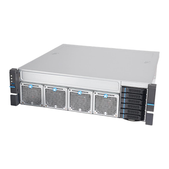
ROC300-TA45
3U GPGPU short Depth Edge
User Manual
Intel® Xeon Silver Ice Lake 4310 12 Cores 2.1/3.3 GHz, 120W, 18MB cache
Dual Nvidia MXM RTX A4500 5888 CUDA cores PCIe Gen 4.0 x16
Two Ethernet LAN ports (LAN1, LAN2) and a dedicated IPMI LAN
4x NVMe M.2 (Gen4 x4)
Equipped with latest tool less design, storage, HDD trays, system fa
ns and PCIe riser brackets for easy upgrades and maintenance.
Size: 450.0 x 450.0 x 131.0 mm.
4x 80mm Fan, 11000RPM
Redundant 2U 1600W 1+1 CRPS
F40-U
F40-U
F40-U
Computing Server
Advertisement
Table of Contents

Related Manuals for Star Lake ROC300-TA45


Summary of Contents for Star Lake ROC300-TA45
- Page 1 F40-U F40-U ROC300-TA45 F40-U 3U GPGPU short Depth Edge Computing Server User Manual Intel® Xeon Silver Ice Lake 4310 12 Cores 2.1/3.3 GHz, 120W, 18MB cache Dual Nvidia MXM RTX A4500 5888 CUDA cores PCIe Gen 4.0 x16 ...
-
Page 2: Table Of Contents
Contents/目錄 Chapter1 : General Information...................... 7 Introduction..........................7 Specifications..........................8 Power Supply Options… ......................9 Environmental Specifications....................10 1.4.1 Table1.2 list ..........................10 1.4.2 Dimension Diagram ........................ 10 Feature Overview ....................... 11 1.4.3 Removing the Top Cover...................... 11 Installing the GPU Card... - Page 3 3.4.4 Universal Serial Bus (USB) Ports and Headers ................ 24 Troubleshooting Procedures… ....................24 3.5.1 Before Power On ........................24 3.5.2 No Power ..........................25 3.5.3 No Video ..........................25 3.5.4 System Boot Failure........................ 25 3.5.5 Memory Errors ........................25 3.5.6 Losing the System's Setup Configuration ................
- Page 4 4.2.11 Network Configuration ......................42 4.2.11.1 MAC: (MAC address)-IPv4 Netwrok Configuration ..............42 4.2.11.2 MAC: (MAC address)-IPv6 Netwrok Configuration ..............43 4.2.11.3 Enter Configuration Menu ..................... 43 4.2.11.4 Advanced Configuration ......................43 4.2.12 KMIP Server Configuration ..................... 43 4.2.12.1 CA Certificate .......................... 44 4.2.12.2 Client Certificate ........................
- Page 5 IPMI ............................55 4.4.1 System Event Log ........................56 4.4.2 BMC Network Configuration ....................57 Security ............................. 58 4.5.1 SMCI Securuty Erase Configuration ..................59 4.5.2 Secure Boot ..........................60 4.5.2.1 Enter Audit Mode ........................60 4.5.2.2 Enter Deployed Mode / Exit Deployed Mode ................ 60 4.5.3 Key Management (Available when Secure Boot Mode is set to Custom)......
- Page 6 Microsoft Windows OS Installation ..................68 Driver Installation ........................70 SuperDoctor® 5 ........................71 IPMI ............................71 Logging into the BMC(Baseboard Management Controller)........72...
-
Page 7: Chapter1 : General Information
1 Chapter1 : General Information.. 1.1 Introduction... ROC300-TA45 is an efficient 3U rackmount workstation designed with the most advanced NVIDIA Quadro RTX (A4500) professional GPU, specifically designed for the most demanding workflows of today. Experience GPU acceleration performance through innovative computers and mobile devices that combine real-time ray tracing, programmable shading technology, and artificial intelligence. -
Page 8: Specifications
1.2 Specifications... Model Name ROC300-TA45 Form Factor EATX/ ATX/ Micro ATX Intel Xeon Silver Ice Lake 4310 with Fansink Chipset C621A Memory DDR4 256GB (4x 64GB) Display 1x VGA (AST2500) 2x NVIDIA MXM A4500 with Fansink Storage 2x M.2 2TB NVMe... -
Page 9: Power Supply Options
1.3 Power Supply Options… 1.3.1 Features 1.3.1.1 A High Reliability PDB(power distribution board) 1.3.1.2 CRPS Module Compatible 1.3.1.3 2U Narrow Form Factor 1.3.1.4 Meet PMBus 1.2 1.3.1.5 Design for 5,000 Meter above Sea level 1.3.1.6 High Reliability 1.3.1.7 Low Ripple & Noise 1.3.1.8 Over Current Protection 1.3.1.9 Over Temperature Protection 1.3.1.10... -
Page 10: Environmental Specifications
1.4 Environmental Specifications... 1.4.1 Table1.2 list 1.4.2 Dimension Diagram... -
Page 11: Feature Overview
1.4.3 Feature Overview 1.5 Removing the Top Cover... -
Page 12: Installing The Gpu Card
1.6 Installing the GPU Card... 1.6.1 Remove the PCIe slot cover 1.6.2 Plug the MXM carrier card with MXM GPU card into the PCIe slot1 (then 7 for 2nd MXM card) 1.6.3 Plug GPU power into the MXM carrier board ✽... -
Page 13: Installing Disk Drives
1.7 Installing Disk Drives... 1.7.1 Installing SSD in the Mobile SSD tray Figure 2.5Removing the mobile SAS / SATA HDD trays 1. Press the tray button and release the lever as shown. 2. Pull the SSD assembly out of the drive bay. 1. -
Page 14: Psu Installation And Removal
1.8 PSU Installation and Removal... 1.8.1 CRPS module installation 1. Insert CRPS module into the PSU cage and push until it is secured into place. 1.8.2 CRPS module removal 1. Press the latch without release as shown. 2. Pull the module handle to remove it from the PSU cage. 1.9 Slide Rail or Pallet... - Page 15 Engage T-pins with the slots on the inner rail as shown. Secure the inner rail with one screw. Install the chassis in the cabinet with the slide rail or pallet supplied /...
-
Page 16: Chapter2 : Operation
2 Chapter2 : Operation.. 2.1 The Front Panel... (Overview) 2.1.1 Switch, Buttons and I/O Interfaces. 2.1.2 LED indicators for System Status 2.1.3 LED Indicators for SSD Power & Status 2.2 The Rear Panel... -
Page 17: Plug The Ac Power With Standard Iec Power Cable
2.2.1 Plug the AC power with standard IEC power cable 2.2.2 Plug the cable into the I/O jack by the Device 2.2.3 Broke the cover to install function card into PCIe slot 2.3 Replacing the system Cooling Fan... -
Page 18: Chapter 3 : Motherboard Overview
3 Chapter 3 : Motherboard Overview 3.1 Motherboard Image…... -
Page 19: Motherboard Layout
3.2 Motherboard Layout… ✽ Notes: CPU SLOT1/3/5/7 : PCIe 4.0 x16 Slots * SLOT1 will be disabled when either M.2-C01 or M.2-C02 is in use. * SLOT1 will change to PCIe x8 when M.2-C03 or/and M.2-C04 are in use. * SLOT3/5/7 will change to PCIe x8 when SLOT2/4/6 is in use respectively. CPU SLOT2/4/6 : PCIe 4.0 x16 Slots (PCIe 4.0 x8 link) - Page 20 Notes: • See Chapter 2 for detailed information on jumpers, I/O ports, and JF1 front panel connections. • " " indicates the location of Pin 1. • Jumpers/LED indicators not indicated are used for testing only. • Use only the correct type of onboard CMOS battery as specified by the manufacturer. Do not install the onboard battery upside down to avoid possible explosion.
-
Page 21: System Diagram
3.3 System Diagram… Memory Support and Installation… Memory supports up to 1 TB of ECC RDIMM, 4 TB of 3DS RDIMM, 2 TB of LRDIMM, 4 TB of 3DS LRDIMM, and 4 TB of Intel Optane Persistent Memory (PMem) 200 Series with speeds of up to 3200 MHz (2DPC) in 16 DDR4 (288-pin) SMD DIMM slots. -
Page 22: Dimm Installation
3.4.1 DIMM Installation Insert the desired number of DIMMs into the memory slots based on the recommended DIMM population tables in the previous section. Locate DIMM memory slots on the motherboard as shown on the right. Push the release tabs outwards on both ends of the DIMM slot to unlock ... -
Page 23: Dimm Removal
Push both ends of the module straight down into the slot until the module snaps into place. Press the release tabs to the lock positions to secure the DIMM module into the slot. 3.4.2 DIMM Removal Press both release tabs on the ends of the DIMM module to unlock it. Once the DIMM module is loosened, remove it from the memory slot. -
Page 24: Universal Serial Bus (Usb) Ports And Headers
3.4.4 Universal Serial Bus (USB) Ports and Headers There are four USB 3.2 Gen. 1 ports (USB5, USB6, USB7, USB8) located on the rear I/O panel, and one USB 3.2 Gen. 1 header (USB2/3) located on the motherboard to provide front USB access. One USB 3.2 Gen. -
Page 25: No Power
3. Remove all add-on cards. 4. Install the CPU (making sure it is fully seated) and connect the front panel connectors to the motherboard. 3.5.2 No Power 1. Make sure that there are no short circuits between the motherboard and the chassis. 2. -
Page 26: Losing The System's Setup Configuration
3.5.6 Losing the System's Setup Configuration 1. Make sure that you are using a high-quality power supply. A poor-quality power supply may cause the system to lose the CMOS setup information. Refer to Chapter 1 for details on recommended power supplies. 2. -
Page 27: Chapter 4 : Uefi Bios
4 Chapter 4 : UEFI BIOS 4.1 Introduction This chapter describes the AMIBIOS™ Setup utility for the motherboard. The BIOS is stored on a chip and can be easily upgraded using a flash program. Starting the Setup Utility To enter the BIOS Setup Utility, hit the <Delete> key while the system is booting-up. (In most cases, the <Delete>... - Page 28 System Date/System Time Use this option to change the system date and time. Highlight System Date or System Time using the arrow keys. Enter new values using the keyboard. Press the <Tab> key or the arrow keys to move between fields. The date must be entered in MM/DD/YYYY format. The time is entered in HH:MM:SS format.
-
Page 29: Advanced Setup Configurations
Advanced Setup Configurations 4.2.1 Use the arrow keys to select the Advanced menu and press <Enter> to access the submenu items: Warning: Take caution when changing the Advanced settings. An incorrect value, a very high DRAM frequency, or an incorrect DRAM timing setting may make the system unstable. When this occurs, revert to default manufacturer settings. -
Page 30: Cpu Configuration
The options are Disabled and Enabled. INT19 (Interrupt 19) Trap Response Interrupt 19 is the software interrupt that handles the boot disk function. When this feature is set to Immediate, the ROM BIOS of the host adapters will "capture" Interrupt 19 at Bootup immediately and allow the drives that are attached to these host adapters to function as bootable disks. -
Page 31: Cpu1 Core Disable Bitmap
4.2.4 CPU1 Core Disable Bitmap CPU1 Core Diable Bitmap Available Bitmap: This feature displays the available bitmap. Core Disable Bitmap(Hex) Enter a value to enable or disable the cores for the CPU in socket 0. Hyper-Threading (ALL) (Available when supported by the CPU) Select Enable to support Intel Hyper-threading Technology to enhance CPU performance. - Page 32 PPIN Control Select Unlock/Enable to use the Protected-Processor Inventory Number (PPIN) in the system. The options are Lock/Disable and Unlock/Enable. AES-NI Select Enable to use the Intel Advanced Encryption Standard (AES) New Instructions (NI) to ensure data security. The options are Disable and Enable. Total Memory Encryption (TME) (Available when CPU supports TME capability) Use this feature to enable the Total Memory Encryption (TME) function for physical memory protection.
-
Page 33: Advanced Power Management Configuration
Owner EPOCH , the other is manually entered by the user. Each EPOCH is 64-bit. The options are Change to New Random Owner EPOCHs and Manual User Defined Owner EPOCHs. Note: Changing the Owner EPOCH value will lose the data in enclaves. Software Guard Extensions Epoch 0 (Available when "Select Owner EPOCH input type"... -
Page 34: Cpu P State Control
performance. Select Power to optimize energy efficiency over performance. The options are Maximum Performance, Performance, Balanced Performance, Balanced Power, and Power. 4.2.5.1 CPU P State Control This feature allows you to configure the following CPU power settings: SpeedStep (P-States) Intel SpeedStep Technology allows the system to automatically adjust processor voltage and core frequency to reduce power consumption and heat dissipation. -
Page 35: Cpu C State Control
Native Mode allows the OS to choose a P-state. Selecting Out of Band Mode allows the hardware to autonomously choose a P-state without OS guidance. Selecting Native Mode with No Legacy Support functions as Native Mode with no support for older hardware. The options are Disable, Native Mode, Out of Band Mode, and Native Mode with No Legacy Support. - Page 36 • Global MMIO Low Base / Limit • Global MMIO High Base / Limit • Pci-e Configuration Base / Size Degrade Precedence Use this feature to set degrade precedence when system settings are in conflict. Select Topology Precedence to degrade Features. Select Feature Precedence to degrade Topology. The options are Topology Precedence and Feature Precedence.
-
Page 37: Memory Configuration
Select Disable to support PCIe remote peer-to-peer relaxed writing ordering, which will allow hardware to enforce peer-to-peer write ordering. The options are Disable and Enable. Stale AtoS Use this feature to optimize the A to S directory. The options are Disable, Enable, and Auto. LLC Dead Line Alloc Select Enable to optimally fill dead lines in LLC. -
Page 38: I/O Configuration
Use this feature to set the percentage of memory space to be used for UEFI ARM mirroring for memory security enhancement. Correctable Error Threshold Use this feature to specify the threshold value for correctable memory-error logging, which sets a limit on the maximum number of events that can be logged in the memory error log at a given time. -
Page 39: Intel® Vt For Directed I/O(Vt-D)
strict-ordering rules of PCI bus for a transaction to be completed prior to other transactions that have already been enqueued. The options are No and Yes. 4.2.7.3 Intel® VT for Directed I/O(VT-d) Intel® VT for Directed I/O (VT-d) Select Enable to use Intel Virtualization Technology for Direct I/O VT-d support by reporting the I/O device assignments to the VMM (Virtual Machine Monitor) through the DMAR ACPI tables. -
Page 40: South Bridge
default setting is 25 (in bits). CfgBar Attribute Use this feature to set the VMD Configuration Bar attribute (e.g. 64-bit or Prefetchable.) The options are 32-bit non-prefetchable, 64-bit non-prefetchable, and 64-bit prefetchable. MemBar1 Size Use this feature to set the VMD Memory Bar1 size (in bits. Minimum is 20 bits.) The default setting is 25 (in bits). -
Page 41: Pch Sata Configuration
•General ME Configuration •Oper. Firmware Version •Backup Firmware Version •Recovery Firmware Version •ME Firmware Status #1 •ME Firmware Status #2 •Current State •Error Code 4.2.10 PCH SATA Configuration When this submenu is selected, the AMI BIOS automatically detects the presence of the SATA devices that are supported by the Intel PCH chip and displays the following features: SATA Controller This feature enables or disables the onboard SATA controller supported by the Intel PCH chip. -
Page 42: Network Configuration
connected to a Solid State drive or a Hard Disk Drive. The options are Hard Disk Drive and Solid State Drive. 4.2.11 Network Configuration Network Stack Select Enabled to enable PXE (Preboot Execution Environment) or UEFI (Unified Extensible Firmware Interface) for network stack support. The options are Disabled and Enabled. *If the feature above is set to Enable, the following features will become available for configuration: IPv4 PXE Support Select Enabled to enable IPv4 PXE boot support. -
Page 43: Mac: (Mac Address)-Ipv6 Netwrok Configuration
4.2.11.2 MAC: (MAC address)-IPv6 Netwrok Configuration 4.2.11.3 Enter Configuration Menu The following information will display: Interface Name / Interface Type / MAC address / Host addresses / Route Table / Gateway addresses / DNS addresses Interface ID Use this feature to change/enter the 64 bit alternative interface ID for the device. The string format is colon separated. -
Page 44: Ca Certificate
4.2.12.1 CA Certificate For the CA certificate, use this feature to enroll factory defaults or load the KMS TLS certificates from the file. The options are Update, Delete, and Export. 4.2.12.2 Client Certificate For the client certificate, use this feature to enroll factory defaults or load the KMS TLS certificates from the file. -
Page 45: Super Io Configuration
1G, 1.5G, 1.75G, 2G, 2.25G, 3G, and Auto. NVMe Firmware Source The feature determines which type of NVMe firmware should be used in your system. The options are Vendor Defined Firmware and AMI Native Support. VGA Priority Use this feature to select VGA priority when multiple VGA devices are detected. Select Onboard to give priority to your onboard video device. -
Page 46: Serial Port 1 Configuration
4.2.14.1 Serial Port 1 Configuration This submenu allows you to configure the settings of Serial Port 1. Serial Port 1 Select Enabled to enable the selected onboard serial port. The options are Disabled and Enabled. Device Settings (Available when the Serial Port 1 is set to Enabled) This feature displays the status of a serial port specified by the user. - Page 47 characters into one or more bytes. The options are VT100, VT100+, VT-UTF8, and ANSI. Bits Per Second Use this feature to set the transmission speed for a serial port used in Console Redirection. Make sure that the same speed is used in the host computer and the client computer. A lower transmission speed may be required for long and busy lines.
-
Page 48: Console Redirection Settings (Available When The Console Redirection Is Set To Enabled)
legacy console redirection is disabled before booting the OS. When set to Always Enable, legacy console redirection remains enabled when booting the OS. The options are Always Enable and BootLoader. SOL/COM2 Console Redirection Select Enabled to use the SOL port for Console Redirection. The options are Disabled and Enabled. 4.2.14.3.2 Console Redirection Settings (Available when the Console Redirection is set to Enabled) Use this feature to specify how the host computer will exchange data with the client computer, which is... -
Page 49: Console Rediredtion Settings (Available When The Console Redirection Ems Is Set To Enable)
The options are Disabled and Enabled. Resolution 100x31 Select Enabled for extended-terminal resolution support. The options are Disabled and Enabled. Legacy OS Redirection Resolution Use this feature to select the number of rows and columns used in Console Redirection for legacy OS support. -
Page 50: Acpi Settings
Flow Control EMS Use this feature to set the flow control for Console Redirection to prevent data loss caused by buffer overflow. Send a "Stop" signal to stop sending data when the receiving buffer is full. Send a "Start" signal to start sending data when the receiving buffer is empty. - Page 51 SHA256 PCR Bank Use this feature to disable or enable the SHA256 Platform Configuration Register (PCR) bank for the installed TPM device. The options are Disabled and Enabled. Pending Operation Use this feature to schedule a TPM-related operation to be performed by a security device for system data integrity.
-
Page 52: Http Boot Configuration
protection, confidentiality, and integrity of data stored or created on the system. Use this feature to enable or disable TXT Suppport. The options are Disabled and Enabled. Note 1: If the option for this feature (TXT Support) is set to Enabled, be sure to dis-able EV DFX (Device Function On-Hide support when it is present in the BIOS for the system to work properly. -
Page 53: Add An Attempt
4.2.18.3 Add an Attempt 4.2.18.4 Delete Attempts 4.2.18.5 Change Attempt Order 4.2.19 Intel® i210 Gigabit Netwrok Connection – (MAC address) 4.2.19.1 Firmware Image Properties The following information will display: • Option ROM version • Unique NVM/EEPROM ID • NVM Version 4.2.19.2 NIC Configuration Link Speed... -
Page 54: Tls Authenticate Configuration
This feature displays the Virtual MAC address for this computer. Mac addresses are six two-digit hexadecimal numbers. 4.2.20 TLS Authenticate Configuration This submenu allows you to configure Transport Layer Security (TLS) settings. 4.2.20.1 Server CA Configuration / Client Certification Configuration 4.2.20.2 Enroll Certification 4.2.20.3... -
Page 55: Change Smbios Event Log Settings
4.3.1 Change SMBIOS Event Log Settings Enabling/Disabling Options SMBIOS Event Log Change this feature to enable or disable all features of the SMBIOS Event Logging during system boot. The options are Disabled and Enabled. *If this feature is set to Enable, the following features will become available for configuration: Erasing Settings Erase Event Log If No is selected, data stored in the event log will not be erased. -
Page 56: System Event Log
BMC Firmware Revision This feature indicates the IPMI firmware revision used in your system. IPMI STATUS (Baseboard Management Controller) This feature indicates the status of the IPMI firmware installed in your system. 4.4.1 System Event Log Enabling/Disabling Options SEL Components Select Enabled for all system event logging at boot up. -
Page 57: Bmc Network Configuration
4.4.2 BMC Network Configuration BMC Network Configuration Update IPMI LAN Configuration Select Yes for the BIOS to implement all IP/MAC address changes at the next system boot. The options are No and Yes. *If the feature above is set to Yes, the following features will become available for configuration: Configure IPv4 Support This section displays configuration features for IPV4 support. -
Page 58: Security
IPv6 Support Use this feature to enable IPv6 support. The options are Enabled and Disabled. *If the feature above is set to Enabled, the following features will become available for configuration: Configuration Address Source This feature allows you to select the source of the IP address for this computer. If Static is selected, you will need to know the IP address of this computer and enter it to the system manually in the field. -
Page 59: Smci Securuty Erase Configuration
Administrator Password Press <Enter> to create a new or change an existing administrator password. Password Check Select Setup for the system to check for a password at Setup. Select Always for the system to check for a password at bootup or upon entering the BIOS Setup utility. The options are Setup and Always. 4.5.1 SMCI Securuty Erase Configuration Note: This submenu becomes configurable when a storage device has been plugged into the motherboard. -
Page 60: Secure Boot
4.5.2 Secure Boot Note: For detailed instructions on how to configure Security Boot settings, please refer to the Security Boot Configuration User's Guide posted on the web page under the link: http://www.supermicro.com/support/manuals/. When you select this submenu and press the <Enter> key, the following items will display: •System Mode •Vendor Keys •Secure Boot... -
Page 61: Restore Factory Keys
4.5.3.1 Restore Factory Keys Use this feature to Install factory default secure boot key databases. The options are Yes and No. Select Yes will reset system to the User mode. 4.5.3.2 Reset to Setup Mode Use this feature to delete all secure boot key databases from NVRAM. Select Yes will reset system to the Setup mode. -
Page 62: Authorized Signatures
Update Select Yes to load the Key Exchange Keys from the manufacturer's defaults. Select No to load thenKey Exchange Keys from a file. Append Select Yes to add the Key Exchange Keys from the manufacturer's defaults list to the existing Key Exchange Keys. -
Page 63: Osrecovery Signature
This feature allows you to export the DBT to an available file system. Update Select Yes to load the DBT from the manufacturer's defaults. Select No to load the DBT from a file. Append Select Yes to add the DBT from the manufacturer's defaults list to the existing DBT. Select No to load the DBT from a file. -
Page 64: Set Admin Passwrod
• Security Subsystem Class • Security Supported • Security Enabled • Security Locked • Security Frozen • User Pwd Status • Admin Pwd Status 4.5.7 Set Admin Passwrod Press <Enter> to create a new admin password. 4.5.8 Set User Passwrod Press <Enter>... - Page 65 Boot Mode Select Use this item to select the type of device that the system is going to boot from. The options are Legacy, UEFI, and Dual. Legacy to EFI Support Select Enabled to boot EFI OS support after Legacy boot order has failed. The options are Disabled and Enabled.
-
Page 66: Delete Boot Option
4.6.1 Delete Boot Option This feature allows you to select a boot device to delete from the boot priority list. Delete Boot Option Use this feature to remove an EFI boot option from the boot priority list. 4.6.2 UEFI Network Drive BBS Priorities This feature sets the system boot order of detected devices. - Page 67 Save Options Discard Changes and Exit Use this feature to quit the BIOS Setup without making any permanent changes to the system configuration and reboot the computer. Save Changes and Reset When you have completed the system configuration changes, use this feature to leave the BIOS setup utility and reboot the computer for the new system configuration parameters to take effect.
-
Page 68: Appendix A Bios Post Codes
Use this feature to retrieve user-defined settings that were saved previously. Boot Override Listed in this section are other boot options for the system (i.e., Built-in EFI shell). Select an option and press <Enter>. Your system will boot to the selected boot option. 5 Appendix A BIOS POST Codes... - Page 69 During Windows Setup, continue to the dialog where you select the drives on which to install Windows. If the disk you want to use is not listed, click on “Load driver” link at the bottom left corner.
-
Page 70: Driver Installation
To load the driver, browse the USB flash drive for the proper driver files. • For RAID, choose the SATA/sSATA RAID driver indicated then choose the storage drive on which you want to install it. • For non-RAID, choose the SATA/sSATA AHCI driver indicated then choose the storage drive on which you want to install it. -
Page 71: Superdoctor® 5
Note: Click the icons showing a hand writing on paper to view the readme files for each item. Click the computer icons to the right of these items to install each item (from top to bottom) one at a time. After installing each item, you must re-boot the system before moving on to the next item on the list. -
Page 72: Logging Into The Bmc(Baseboard Management Controller)
6.5 Logging into the BMC(Baseboard Management Controller) Supermicro ships standard products with a unique password for the BMC ADMIN user. This password can be found on a label on the moth...
Need help?
Do you have a question about the ROC300-TA45 and is the answer not in the manual?
Questions and answers