Table of Contents
Advertisement
Quick Links
Advertisement
Table of Contents

Related Manuals for Soundigital GAN 1500.5


Summary of Contents for Soundigital GAN 1500.5
- Page 1 OWNER´S MANUAL...
-
Page 2: Table Of Contents
Introduction ................................3 Package contents.............................. 3 Safety instructions ............................. 4 Technologies News ............................... 5 Advantages ..........................6 Panels description Audio controls ........................... 7 Power, Audio inputs and outputs ................... 8 Installation sequence ............................9 Electrical dimensioning ..........................10 Audio inputs RCA inputs .......................... -
Page 3: Introduction
INTRODUCTION Dear Consumer, Congratulations, you have just acquired a SounDigital product of the highest technology and quality, so we thank you for your trust. SounDigital products are made with raw materials of the highest quality standards, and the most modern processes, equipment and technology are used in their production. -
Page 4: Safety Instructions
Wear gloves, safety glasses firmly. Avoid fixing to metallic and all necessary PPE during parts of the vehicle, as this the installation of SounDigital procedure may cause ground amplifiers. looping (noise); THIS "WARNING" SIGN ALERTS THE USER OF IMPORTANT INFO. NOT FOLLOWING THESE INSTRUCTIONS MAY CAUSE INJURIES TO THE USER OR DAMAGE TO THE EQUIPMENT. -
Page 5: News
Tune in to the future of sound! The electronic revolution has arrived at SounDigital, and GaN is the star of this transformation! With high-performance amplifiers, unrivaled durability and eco- consciousness, the future of sound is brighter than ever. Get ready for an extraordinary sound experience that pushes the boundaries of the ordinary and delivers the sound of your dreams. -
Page 6: Advantages
ADVANTAGES Advantages of using SounDigital amplifiers with GaN technology: SounDigital's GaN-based power amplifiers have several advantages that make them attractive for use in audio systems: High energy efficiency GaN has a high electron mobility, which allows GaN power amplifiers to convert significantly less electrical energy into heat. -
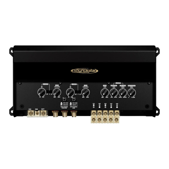
Page 7: Panels Description
PANELS DESCRIPTION X-OVER X-OVER X-OVER SUBSONIC LOW PASS GAIN GAIN GAIN BASS BOOST CH1-CH2 CH3-CH4 10Hz 100Hz 50Hz HP F LP HP F LP 40Hz 50Hz 500Hz +12dB CH1-CH2 CH1-CH2 CH3-CH4 CH5 R + L INPUT SOURCE INPUT SOURCE CH3-CH4 BATT 11 12 Channels 1 and 2... -
Page 8: Power, Audio Inputs And Outputs
PANELS DESCRIPTION 22 24 28 30 23 25 29 31 33 34 Negative power supply connector (GND) Remote power supply connector (REM) Positive power supply connector (+12VDC) Channel 1 Channel 2 Channel 3 Audio inputs – RCA connectors Channel 4 Channel 5 L Channel 5 R Channel 1... -
Page 9: Installation Sequence
INSTALLATION SEQUENCE BEFORE PROCEEDING WITH THE INSTALLATION, UNPLUG THE NEGATIVE TERMINAL FROM ALL OF THE BATTERIES, TO AVOID FIRE, DAMAGE TO THE AMPLIFIER AND THE USERS THEMSELVES. Warning! Ø Fix the amplifier so that the connectors can be easily accessed; Ø... -
Page 10: Electrical Dimensioning
ELECTRICAL DIMENSIONING AND AUDIO INPUTS ELECTRICAL DIMENSIONING For proper operation of your SounDigital amplifier, you need the proper dimensioning of the electrical system and the cables used. The table below shows the minimum section of GND cables, +12VDC cables and speaker output cables according to the power generated by the amplifier. -
Page 11: Gain Adjustment (Channels 1 To 4)
GAIN SETTING (CHANNELS 1 TO 4) X-OVER GAIN CH1-CH2 HP F LP GAIN SETTING Necessary equipament: Ø On the audio player, set the fader Ø Digital AC voltmeter; control to center position; Ø Media with sine wave test tone 60Hz Ø... -
Page 12: Crossover Adjustment (Channels 1 To 4)
CROSSOVER SET UP (CHANNELS 1 TO 4) X-OVER X-OVER GAIN GAIN CH1-CH2 CH3-CH4 HP F LP HP F LP CH1-CH2 CH1-CH2 CH3-CH4 CH5 R + L INPUT SOURCE INPUT SOURCE CH3-CH4 "HP" Set variable control in "F" Set variable control in "LP"... -
Page 13: Channel 5 Gain Adjustment (Subwoofer) And Sd Rlc
Download the tracks for set up in https://soundigitalusa.com/tracks-for-set-up/ EXTERNAL LEVEL CONTROL - SD RLC (*Not included) The SD RLC is an easy-to-install external level control accessory that allows you to tune the level of SOUNDIGITAL amplifiers that have remote level POWER CLIP control. -
Page 14: Channel 5 Bass Boost Adjustment (Subwoofer)
CHANNEL 5 BASS BOOST ADJUSTMENT (SUBWOOFER) USING BASS BOOST The Amplifier Bass Boost setting enables the user to boost the sound intensity at low frequencies of the sound system, where boost intensity can be adjusted. This is a semi-parametric equalizer type circuit with ''Q'' value for the fixed filter, with an intensity boost adjustment from 0 to +12dB (16 times), and a central frequency adjustment of the filter in 50Hz, making it versatile for several types of sound systems. -
Page 15: Channel 5 Crossovers Adjustment (Subwoofer)
ADJUSTMENT OF CHANNEL 5 CROSSOVERS (SUBWOOFER) HOW TO ADJUST THE CROSSOVERS X-OVER GAIN SUBSONIC LOW PASS BASS BOOST 10Hz 100Hz 50Hz 40Hz 50Hz 500Hz +12dB ►The use of the two associated filters can form a bandpass filter, as in the figure below, where the point "A"... -
Page 16: Wiring Diagram
WIRING DIAGRAM 2 CHANNELS WIRING DIAGRAM (per channel) + SUBWOOFER X-OVER X-OVER X-OVER GAIN GAIN GAIN SUBSONIC LOW PASS BASS BOOST CH1-CH2 CH3-CH4 10Hz 100Hz 50Hz HP F LP HP F LP 40Hz 50Hz 500Hz +12dB CH1-CH2 CH1-CH2 CH3-CH4 CH5 R + L INPUT SOURCE INPUT SOURCE CH3-CH4... -
Page 17: Two Channels Wiring Diagram (In Bridge) + Subwoofer
WIRING DIAGRAM 2 CHANNELS WIRING DIAGRAM (in Bridge) + SUBWOOFER X-OVER X-OVER X-OVER GAIN GAIN GAIN SUBSONIC LOW PASS BASS BOOST CH1-CH2 CH3-CH4 10Hz 100Hz 50Hz HP F LP HP F LP 40Hz 50Hz 500Hz +12dB CH1-CH2 CH1-CH2 CH3-CH4 CH5 R + L INPUT SOURCE INPUT SOURCE CH3-CH4... -
Page 18: Four Channels Wiring Diagram + Subwoofer
WIRING DIAGRAM 4 CHANNELS WIRING DIAGRAM (per channel) + SUBWOOFER X-OVER X-OVER X-OVER GAIN GAIN GAIN SUBSONIC LOW PASS BASS BOOST CH1-CH2 CH3-CH4 10Hz 100Hz 50Hz HP F LP HP F LP 40Hz 50Hz 500Hz +12dB CH1-CH2 CH1-CH2 CH3-CH4 CH5 R + L INPUT SOURCE INPUT SOURCE CH3-CH4... -
Page 19: Battery Connection Diagram
BATTERY CONNECTION DIAGRAM When necessary the association of one or more battery banks to supply the necessary current to the amplifier, it is recommended to use batteries of the same brand, model, and if possible the same manufacturing lot so that the system has the maximum performance. -
Page 20: Parameters
The values presented are based on measurements performed in Updates of information made in this document will always be SounDigital's laboratories. All the equipment used in the assays, tests, published and made available for consumer consultation, free of measurements and gauging of the technical parameters of SounDigital charge, on the brand's websites.
Need help?
Do you have a question about the GAN 1500.5 and is the answer not in the manual?
Questions and answers