SMA Home Storage HS-BM-3.28-10 Operating Manual
Hide thumbs
Also See for Home Storage HS-BM-3.28-10:
- Manual (99 pages) ,
- Service manual for installers (14 pages)

Related Manuals for SMA Home Storage HS-BM-3.28-10


Summary of Contents for SMA Home Storage HS-BM-3.28-10
- Page 1 Operating Manual SMA Home Storage HS-BM-3.28-10 ENGLISH HS-BM-3.28-10-BE-en-10 | Version 1.0...
- Page 2 Legal Provisions The information contained in these documents is the property of SMA Solar Technology AG. No part of this document may be reproduced, stored in a retrieval system, or transmitted, in any form or by any means, be it electronic, mechanical, photographic, magnetic or otherwise, without the prior written permission of SMA Solar Technology AG.
-
Page 3: Table Of Contents
SMA Solar Technology AG Table of contents Table of contents Information on this Document..................... Validity................................Target Group ..............................Content and Structure of this Document......................Levels of Warning Messages.......................... Symbols in the Document..........................Typographies in the document........................Designations in the Document......................... - Page 4 Table of contents SMA Solar Technology AG Overview of the Connection Area........................35 Wiring overview with hybrid inverter ......................36 Requirements for the electrical connection..................... 36 7.3.1 Grounding cable requirements ........................36 7.3.2 DC cable requirements ........................... 36 7.3.3 Battery data cable requirements ........................37 Electrical Connection Procedure........................
- Page 5 SMA Solar Technology AG Table of contents 19 UK Declaration of Conformity ....................65 20 Contact ............................66 Operating Manual HS-BM-3.28-10-BE-en-10...
-
Page 6: Information On This Document
The latest version of this document and additional information about the product can be found in PDF format and as an eManual at www.SMA-Solar.com. You can also call up the eManual via the user interface of the product. Illustrations in this document are reduced to the essential information and may deviate from the real product. -
Page 7: Symbols In The Document
(e.g., parameter names) Designations in the Document Complete designation Designation in this document SMA Home Storage 3.28 kWh module SMA Home Storage, battery module, battery, battery system, product SMA Home Storage Base Unit Base Sunny Boy Smart Energy Hybrid inverter, inverter... - Page 8 1 Information on this Document SMA Solar Technology AG Title and information content Type of information SUNNY BOY SMART ENERGY 3.6 / 4.0 / 5.0 / 6.0 Operating manual Mounting, installation, commissioning, configuration, operation, troubleshooting and decommissioning SUNNY TRIPOWER 5.0 / 6.0 / 8.0 / 10.0 SMART ENERGY...
-
Page 9: Safety
The product is not suitable for supplying life-sustaining medical devices. A power outage must not lead to personal injury. The product must only be used in countries for which it is approved or released by SMA Solar Technology AG and the grid operator. - Page 10 2 Safety SMA Solar Technology AG DANGER Danger to life due to electric shock when live components or DC cables are touched The DC cables connected to a battery may be live. Touching live DC cables results in death or serious injury due to electric shock.
- Page 11 SMA Solar Technology AG 2 Safety DANGER Danger to life due to electric shock when live components are touched on opening the product High voltages are present in the live parts and cables inside the product during operation. Touching live parts and cables results in death or lethal injuries due to electric shock.
- Page 12 2 Safety SMA Solar Technology AG WARNING Risk of injury due to toxic substances, gases and dusts. In rare cases, damages to electronic components can result in the formation of toxic substances, gases or dusts inside the product. Touching toxic substances and inhaling toxic gases and dusts can cause skin irritation, burns or poisoning, trouble breathing and nausea.
- Page 13 SMA Solar Technology AG 2 Safety NOTICE Damage to the battery modules due to moisture or corrosive substances Moisture or corrosive substance penetration can damage the product and impair its functionality. • Do not immerse battery modules in liquid. • Do not expose battery cells to corrosive substances (e.g., ammonia, salt).
-
Page 14: Scope Of Delivery
Scope of delivery of battery modules Check the scope of delivery for any externally visible damage. If visible damages are detected, document the damaged areas and immediately inform SMA Solar Technology AG. Never commission the battery if components are damaged. -
Page 15: Scope Of Delivery Of Base
Scope of delivery of base Check the scope of delivery for any externally visible damage. If visible damages are detected, document the damaged areas and immediately inform SMA Solar Technology AG. Never commission the battery system if components are damaged. -
Page 16: Product Overview
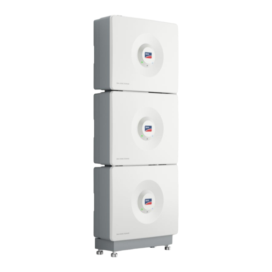
4 Product Overview SMA Solar Technology AG 4 Product Overview System Overview Figure 3: Design of the system (example) HS-BM-3.28-10-BE-en-10 Operating Manual... -
Page 17: Product Description
SMA Solar Technology AG 4 Product Overview Product Description Figure 4: Design of the product Position Designation LEDs The LEDs indicate the operating state of the product. DC switch Disconnects the product from the power path on the DC side. - Page 18 4 Product Overview SMA Solar Technology AG Symbol Explanation Potentially explosive substances warning Improper handling or fire can cause the product to ignite or explode. Corrosive substances warning The product contains corrosive substances that can cause severe injury if they come into di- rect contact with the skin.
-
Page 19: Interfaces And Functions
4.4.1 RJ45 connection The battery is equipped with an RJ45 terminal as standard. The battery can communicate via cables with SMA inverters via this RJ45 terminal (information on supported SMA products at www.SMA-Solar.com). For the communicative connection of Sunny Tripower Smart Energy, a pre-assembled communication cable is recommended (see Technical Information "Approved Batteries and Information on Battery Communication Connection"... -
Page 20: Battery Management
4 Product Overview SMA Solar Technology AG LED signal Explanation The blue LED is flashing Communication connection is being established. slowly (2 seconds on and The battery is establishing a connection with the connected inverter. 2 seconds off) The blue LED is glowing There is an active connection to the connected inverter. -
Page 21: Modular Extension Of The Battery Modules
SMA Solar Technology AG 4 Product Overview Range Inverter parameters Inverter behavior Device > Self-consumption > Lower battery In this range, the battery is no longer discharged, discharge limit (BatChaSttMin) even in battery-backup operation. Battery > Areas of application > Minimum... -
Page 22: Transport
• Wear suitable personal protective equipment for all work on the battery. The SMA Home Storage (HS-BM-3.28-10) is classified as dangerous goods: UN 3480 lithium-ion battery, class 9 (dangerous goods designation UN 3480, dangerous goods class 9). The safety information of the battery must be observed (see Technical information "SMA HOME STORAGE - Safety Information"... -
Page 23: Mounting
SMA Solar Technology AG 6 Mounting 6 Mounting Requirements for Mounting 6.1.1 Requirements for the installation site of the battery modules WARNING Danger to life due to fire or explosion Despite careful construction, electrical devices can cause fires. This can result in death or serious injury. -
Page 24: Wall Mounting
6 Mounting SMA Solar Technology AG Figure 8: Recommended clearances (dimensions in mm) Wall Mounting 6.2.1 Wall mounting variants 1 to 5 batteries 4 or 5 batteries Maximum of 5 batteries Figure 9: Wall mounting variants (recommended) Also see: • Requirements for the electrical connection ⇒ page 36 HS-BM-3.28-10-BE-en-10... -
Page 25: Dimensions For Wall Mounting
SMA Solar Technology AG 6 Mounting 6.2.2 Dimensions for wall mounting Figure 10: Position of the anchoring points (dimensions in mm) 6.2.3 Mount the battery modules with wall mounting bracket Additionally required mounting material (not included in the scope of delivery): ☐... - Page 26 6 Mounting SMA Solar Technology AG 3. Secure the wall mounting bracket horizontally on the wall using screws and washers. 4. For battery modules directly above one another: screw the connecting element with 2 supplied screw and washer assemblies to the wall mounting bracket (TX20; torque 2.5 Nm).
- Page 27 SMA Solar Technology AG 6 Mounting 8. Slightly screw in a supplied screw and washer assembly on the wall mounting bracket at the bottom, leaving space for the mounting bracket of the battery module (TX20). 9. Hook the lower battery module in the wall mounting bracket and secure below with the screw and washer assembly provided (TX20;...
-
Page 28: Mounting With Base
6 Mounting SMA Solar Technology AG 11. For battery modules directly above one another: fasten battery module on the left and right to the previous battery module using a supplied screw and washer assembly (TX20; torque 2.5 Nm). Ensure that the battery module is securely in place. -
Page 29: Dimensions For Mounting With Base
SMA Solar Technology AG 6 Mounting 6.3.2 Dimensions for mounting with base Figure 12: Position of the anchoring points (dimensions in mm) 6.3.3 Mounting the battery modules with base Additionally required mounting material (not included in the scope of delivery): ☐... - Page 30 6 Mounting SMA Solar Technology AG 2. Attach fixing bracket with 2 supplied screw and washer assemblies to the base (TX20; torque 2.5 Nm). 3. Mark the position of the drill holes using the fixing bracket. 4. Drill holes and insert the screw anchors if necessary.
- Page 31 SMA Solar Technology AG 6 Mounting 7. Attach battery module on the left and right to the base using supplied screw and washer assembly each (TX20; torque 2.5 Nm). Further procedure for 2 to 3 battery modules directly above one another: 1.
-
Page 32: Back-To-Back
6 Mounting SMA Solar Technology AG Back-to-back 6.4.1 Mounting variants of the back-to-back Figure 13: Mounting variants of the back-to-back Also see: • Requirements for the electrical connection ⇒ page 36 6.4.2 Mounting dimensions for the back-to-back Figure 14: Position of the anchoring points (dimensions in mm) HS-BM-3.28-10-BE-en-10... -
Page 33: Mounting Back-To-Back
SMA Solar Technology AG 6 Mounting 6.4.3 Mounting back-to-back Procedure: 1. Attach 2 fixing brackets to 2 bases using 2 supplied screw and washer assemblies each (TX20; torque 2.5 Nm). 2. Attach the fixing brackets using 2 supplied screw and washer assemblies to each other (TX20;... - Page 34 6 Mounting SMA Solar Technology AG 4. Attach both battery modules on the left and right to the base using a supplied screw and washer assembly each (TX20; torque 2.5 Nm). Ensure that the battery modules are securely in place. 5. If there is an odd number of battery modules, choose a different mounting option for the remaining battery module.
-
Page 35: Electrical Connection
SMA Solar Technology AG 7 Electrical Connection 7 Electrical Connection Overview of the Connection Area Figure 15: Connection areas on the product Position Designation Grounding terminal or equipotential bonding terminal Positive DC connector (type: Multi-Contact MC4) for connecting the battery modules or to the inverter. -
Page 36: Wiring Overview With Hybrid Inverter
DC+ cable DC– cable Speedwire/Ethernet Figure 16: SMA Home Storage with 1 hybrid inverter (example) Requirements for the electrical connection 7.3.1 Grounding cable requirements An additional grounding of the battery modules is required to protect from touch current in case the grounding conductor fails at the terminal of the DC cable. -
Page 37: Battery Data Cable Requirements
Sunny Tripower Smart Energy For the connection between the SMA Home Storage and Sunny Tripower Smart Energy, a pre-assembled battery data cable must be used (SMA order number: HS-COM-CBL-3-10). This battery data cable has an RJ45 and a COM connector. A commercially available network cable can be used as a battery data cable. The cable length and quality do affect the quality of the signal. -
Page 38: Connecting The Battery Data Cable Between The Battery Modules
7 Electrical Connection SMA Solar Technology AG Prerequisite: ☐ Make sure that the battery modules were correctly mounted. Procedure: 1. Disconnect all products from voltage sources. 2. Connect battery modules mounted directly above each other via the supplied grounding cable. To do this, tighten the provided screw and washer assemblies at the connection points closest to each other (TX20;... - Page 39 SMA Solar Technology AG 7 Electrical Connection Prerequisite: ☐ Make sure that the battery modules were correctly mounted. Procedure: 1. Disconnect all products from voltage sources. 2. Detach adapter and RJ45 termination plug of one of the bottom battery data cables. The premounted RJ45 termination plug on the last battery module must not be removed.
-
Page 40: Connection Overview Of The Battery Communication With The Inverter
7 Electrical Connection SMA Solar Technology AG 5. Insert the connector through the adapter and plug the battery data cables together. 6. Secure the connection. To do this, firmly tighten the adapter and the swivel nut. 7. Ensure that the battery data cable is securely in place by pulling slightly on it. -
Page 41: Connecting The Battery Communication System To The Inverter
Connecting the battery communication system to the inverter Additionally required material (not included in the scope of delivery): ☐ Battery data cable with RJ45 connector ☐ Pre-assembled battery data cable for the connection to the Sunny Tripower Smart Energy (SMA order number: HS-COM-CBL-3-10) Prerequisite: ☐... -
Page 42: Connecting The Dc Cables
7 Electrical Connection SMA Solar Technology AG 7. Attach the cable support sleeve between the swivel nut and adapter and secure the cable. To do this, firmly tighten the adapter and the swivel nut. 8. Repeat the procedure for connection on the battery side of the communication cable. - Page 43 SMA Solar Technology AG 7 Electrical Connection 3. Connect the battery modules to each other in series. For this, connect the plug connector of the DC cable BAT+ with the BAT- connector. 4. Prepare the DC cables of the inverter. If needed, crimp the provided MC4 connectors with the cables.
-
Page 44: Commissioning
SMA Solar Technology AG 8 Commissioning Commissioning Procedure This section describes the procedure for commissioning the SMA Home Storage. It provides an overview of the steps, which must be performed in the prescribed sequence. Procedure Check that all installed components have been cor- Section 8.2, page 44... -
Page 45: Example Of The User Interface Of An Inverter
• Logout Help Provides the following functions, for example: • Displaying information on Open Source licenses used • Link to the website of SMA Solar Technology AG Status bar Display of various status information of the system. Operating Manual HS-BM-3.28-10-BE-en-10... -
Page 46: Commissioning The Battery Modules
8 Commissioning SMA Solar Technology AG Current power and cur- Shows the temporal progression of the PV power and the power consump- rent consumption tion of the household over the selected time period, for example. Status display The various areas display information on the current status of the system such as: •... -
Page 47: Checking The Configuration Of The Battery Modules In The Installation Assistant
SMA Solar Technology AG 8 Commissioning Checking the configuration of the battery modules in the installation assistant The user interface available and its functions depend on the inverter. The procedure is described here as an example. Refer to the inverter user manual for detailed information. - Page 48 8 Commissioning SMA Solar Technology AG Also see: • Technical Data ⇒ page 61 • Example of the user interface of an inverter ⇒ page 45 HS-BM-3.28-10-BE-en-10 Operating Manual...
-
Page 49: Disconnecting The Battery Modules From Voltage Sources
SMA Solar Technology AG 9 Disconnecting the battery modules from voltage sources 9 Disconnecting the battery modules from voltage sources 1. Disconnect the inverter from voltage sources. 2. Remove the right side cover from each battery module. 3. Open the cover of the circuit breaker on each battery module. -
Page 50: Performing Cleaning And Maintenance
10 Performing cleaning and maintenance SMA Solar Technology AG 10 Performing cleaning and maintenance NOTICE Damage to the product due to cleaning agents The use of cleaning agents may cause damage to the product and its components. • Clean all battery components with a dry cloth only. -
Page 51: Troubleshooting
SMA Solar Technology AG 11 Troubleshooting 11 Troubleshooting 11.1 Options for troubleshooting Status changes or errors on one or more battery modules can become noticeable in different ways. Status changes or errors Signs on the battery Error with event message Some possible errors are indicated by event messages in Section 11.2, page 51... - Page 52 11 Troubleshooting SMA Solar Technology AG • Restart the system. • If the error persists, contact Service. 11.2.3 Event 9312 Event message: • Undervoltage battery system Explanation: Undervoltage on a battery module LED signal on battery module: Red LED is flashing quickly.
- Page 53 SMA Solar Technology AG 11 Troubleshooting • Check whether the MC4 connectors on all DC connections are correctly positioned. • Wait until the operating temperature of the battery module is back within the specified range. • If the error persists, contact Service.
-
Page 54: Error With Led Display Only
11 Troubleshooting SMA Solar Technology AG 11.2.9 Event 9392 Event message: • Overcurrent charge battery system LED signal on battery module: Red LED is flashing quickly. Corrective measures: • Disconnect the system (battery and inverter) from voltage sources. • Restart the system. -
Page 55: External Appearance Of The Battery Module
SMA Solar Technology AG 11 Troubleshooting 11.4 External appearance of the battery module Changes to the external appearance of the battery modules can also indicate possible errors. Status change of the battery module Corrective measures Discolorations, scratches or signs of wear on the enclo- •... -
Page 56: Decommissioning The Battery Modules
12 Decommissioning the battery modules SMA Solar Technology AG 12 Decommissioning the battery modules To decommission the battery modules completely upon completion of their service life, disassemble the battery modules as described in the following. Requirements: ☐ All circuit breakers of the battery modules are switched off. -
Page 57: Storage
SMA Solar Technology AG 13 Storage 13 Storage Observe the maximum storage period for commissioning To benefit from the full performance of a battery module, it has to be commissioned in the period defined in the liability conditions. Each individual battery module can potentially cause a fire. Any damage to a battery module will increase the fire risk. -
Page 58: Disposal
• Non-critical battery modules are battery modules, for example, whose storage capacity is no longer sufficient. 14.2 Regional providers for the disposal of batteries The latest version of this document including the following table can be found in PDF format at www.SMA-Solar.com. Country/region Supplier... -
Page 59: Reporting Damaged Battery
SMA Solar Technology AG 14 Disposal • Regional providers for the disposal of batteries ⇒ page 58 14.4 Reporting damaged battery • If a battery is damaged, immediately contact the installer or sales partner. 14.5 Disposing of the Battery 1. Immediately decommission the battery if damaged. -
Page 60: Procedure For Receiving A Replacement Device
Technology AG for returning the battery module. 7. If no request is made by SMA Solar Technology AG to return the defective battery module within the storage period, dispose of the defective battery module. Use the transport packaging of the replacement device. -
Page 61: Technical Data
Compatible with SMA STP- Compatible with SMA SB- Device registration via the SMA product registration homepage (my.sma-service.com) within 30 days. The conditions of the SMA limited factory warranty apply. You can find additional information at SMA-solar.com When observing the operating temperature Operating Manual HS-BM-3.28-10-BE-en-10... -
Page 62: Dc Connection
16 Technical Data SMA Solar Technology AG 16.3 DC connection SMA Home SMA Home SMA Home SMA Home SMA Home Storage 3.2 Storage 6.4 Storage 9.6 Storage 12.8 Storage 16.0 Type designation 2 × HS- 3 ×HS- 4 ×HS- 5 ×HS- BM-3.28-10 BM-3.28-10 BM-3.28-10 BM-3.28-10... -
Page 63: Accessories
SMA Solar Technology AG 17 Accessories 17 Accessories Designation Short designation SMA order number Base unit HS-BU-10 Base for floor-mounted SMA Home Storage HS-BU-10 Communication cable to the STP- Battery data cable for the connection between the HS-COM-CBL-3-10 SMA Home Storage and Sunny Tripower Smart Energy This battery data cable has an RJ45 and a CAN connec- tor. -
Page 64: Eu Declaration Of Conformity
2011) and 2015/863/EU (L 137/10, March 31, 2015) (RoHS) SMA Solar Technology AG confirms herewith that the products described in this document are in compliance with the fundamental requirements and other relevant provisions of the aforementioned directives. More information on the availability of the entire declaration of conformity can be found at https://www.sma.de/en/ce-ukca. - Page 65 • The Restriction of the Use of Certain Hazardous Substances in Electrical and Electronic Equipment Regulations 2012 (SI 2012/3032) SMA Solar Technology AG confirms herewith that the products described in this document are in compliance with the fundamental requirements and other relevant provisions of the above-mentioned regulations. More information on the availability of the entire declaration of conformity can be found at https://www.sma.de/en/ce-ukca.
- Page 66 20 Contact SMA Solar Technology AG 20 Contact If you have technical problems with our products, please contact the SMA Service Line. The following data is required in order to provide you with the necessary assistance: • Device type • Serial number •...
- Page 68 www.SMA-Solar.com...
Need help?
Do you have a question about the Home Storage HS-BM-3.28-10 and is the answer not in the manual?
Questions and answers