
Subscribe to Our Youtube Channel
Related Manuals for SMA SUNNY CENTRAL STORAGE 500


Summary of Contents for SMA SUNNY CENTRAL STORAGE 500
- Page 1 Operating Manual SUNNY CENTRAL STORAGE 500/630/720/760/800/850/900/1000 U T I L I T Y G R A ENGLISH SCS-BE-E7-en-12 | 98-118000.02 | Version 1.2...
- Page 2 The information contained in these documents is property of SMA Solar Technology AG. Any publication, whether in whole or in part, requires prior written approval by SMA Solar Technology AG. Internal reproduction used solely for the purpose of product evaluation or other proper use is allowed and does not require prior approval.
-
Page 3: Table Of Contents
Table of Contents SMA Solar Technology AG Table of Contents Information on this Document ..................... Validity ................................8 Target Group ..............................8 Additional Information............................8 Symbols................................8 Typographies ..............................9 Nomenclature ..............................9 Safety............................. 10 Intended Use..............................10 Safety Information ............................11 Personal Protective Equipment......................... - Page 4 Table of Contents SMA Solar Technology AG Mounting of the Inverter........................... 34 4.4.1 Mounting the Inverter on a Foundation ......................34 4.4.2 Mounting the Inverter on a Base........................34 Installation............................. 35 Safety during Installation ..........................35 Preparing the Installation ..........................36 5.2.1...
- Page 5 Table of Contents SMA Solar Technology AG 7.4.2.3 Selecting the Display Format........................... 59 7.4.2.4 Setting the Brightness............................59 Parameter Settings............................60 7.5.1 Information on Setting Parameters ........................60 7.5.2 Setting the Power Control ..........................60 7.5.2.1 Specifying Setpoints ............................60 7.5.2.2...
- Page 6 Table of Contents SMA Solar Technology AG 9.4.4 Checking the Latches, Door Stops and Hinges ....................87 9.4.5 Checking the Inverter Surface ......................... 88 9.4.6 Cleaning the Air Duct and Ventilation Grids ....................89 9.4.7 Cleaning the Ventilation Plate ......................... 89 9.4.8...
- Page 7 13 Operating Data and Parameters ....................130 13.1 BSC Operating Data and Parameters ......................130 13.2 SC-COM Operating Data and Parameters ....................131 14 Technical Data..........................134 14.1 Sunny Central Storage 500..........................134 14.2 Sunny Central Storage 630..........................135 14.3 Sunny Central Storage 720..........................137 14.4 Sunny Central Storage 760..........................138 14.5 Sunny Central Storage 800..........................140...
-
Page 8: Information On This Document
• Training in the installation and commissioning of electrical devices and installations • Knowledge of all applicable standards and directives • Knowledge of and adherence to this manual and all safety information Additional Information Links to additional information can be found at www.SMA-Solar.com. Symbols Symbol Explanation... -
Page 9: Typographies
1 Information on this Document SMA Solar Technology AG Symbol Explanation Indicates a situation which, if not avoided, can result in property damage Information that is important for a specific topic or goal, but is not safety-relevant Indicates a requirement for meeting a specific goal... -
Page 10: Safety
Alterations to the product, e.g. changes or modifications, are only permitted with the express written permission of SMA Solar Technology AG. Unauthorized alterations will void guarantee and warranty claims and in most cases terminate the operating license. SMA Solar Technology AG shall not be held liable for any damage caused by such changes. -
Page 11: Safety Information
2 Safety SMA Solar Technology AG Safety Information This section contains safety information that must be observed at all times when working on or with the product. To prevent personal injury or property damage and to ensure long-term operation of the product, read this section carefully and observe all safety information at all times. - Page 12 2 Safety SMA Solar Technology AG Danger to life from electric shock due to ground fault If there is a ground fault, system components that are supposedly grounded may in fact be live. Touching incorrectly grounded components results in death or serious injuries from electric shock.
- Page 13 2 Safety SMA Solar Technology AG Danger to life from electric shock if the product is not locked If the product is not locked, unauthorized persons will have access to live components carrying lethal voltages. Touching live components can result in death or serious injury due to electric shock.
-
Page 14: Personal Protective Equipment
2 Safety SMA Solar Technology AG Property damage due to dust intrusion and moisture penetration Dust or moisture intrusion can damage the product and impair its functionality. • Do not open the enclosure during rainfall or when humidity exceeds the specified thresholds. The humidity thresholds are: 15% to 95%. -
Page 15: Product Overview
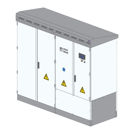
3 Product Overview SMA Solar Technology AG 3 Product Overview System overview The Sunny Central Storage is a battery inverter that converts the direct current supplied by a battery into grid-compliant alternating current. An external MV transformer fitted downstream feeds the alternating current into the utility grid. The Sunny Central Storage can be used in off-grid systems based on diesel generators (gensets). -
Page 16: Devices Of The Inverter
3 Product Overview SMA Solar Technology AG Devices of the Inverter Stop Start Figure 2: Devices of the inverter Position Designation Description Touch Display Different kinds of inverter data can be viewed on the touch display. The touch display is only used to view data. The display screen is ac- tivated by touching the touch display. -
Page 17: Operating And Display Elements
3 Product Overview SMA Solar Technology AG Operating and Display Elements 3.4.1 Function of the Switches 3.4.1.1 Key Switch Figure 3: Switch positions of the key switch Position Designation Switch position Stop Switch position Start 3.4.1.2 AC Disconnection Unit The AC disconnection unit disconnects the inverter from the MV transformer. -
Page 18: Dc Switchgear
3 Product Overview SMA Solar Technology AG 3.4.1.3 DC Switchgear Figure 5: Indicators on the DC load-break switch Position Designation Spring status indicator Position indicator ON button OFF button 3.4.2 Touch Display 3.4.2.1 Design The touch display is used to display instantaneous values and parameter settings. Tapping the symbols on the touch display activates the corresponding functions. -
Page 19: Explanation Of Symbols
3 Product Overview SMA Solar Technology AG The touch display is divided into three areas. Figure 6: Design of the touch display Position Designation Explanation Status info line Number of the active menu, login status and time Information field Area of the main menu... - Page 20 3 Product Overview SMA Solar Technology AG Symbol Designation Explanation Inverter data Representation of the following inverter data: • Device type • Operating state • Symbol for utility grid menu • Symbol for temperature display • Symbol for fan display...
- Page 21 3 Product Overview SMA Solar Technology AG Symbol Designation Explanation Homepage Select this symbol to go to the homepage. Settings • Language selection • Brightness setting • Time setting • Format selection • Password entry Information • OS: version of the operating system •...
-
Page 22: Leds Of The Sc-Com
3 Product Overview SMA Solar Technology AG 3.4.3 LEDs of the SC-COM 3.4.3.1 LEDs on the Enclosure Figure 7: LEDs on the enclosure LED designation Status Explanation POWER glowing green The SC-COM is supplied with voltage. The SC-COM is not supplied with voltage. -
Page 23: Leds On The Network Port
3 Product Overview SMA Solar Technology AG LED designation Status Explanation flashing green The SC-COM is communicating with the devices connected within the system. glowing green Internal communication has taken place in the last five minutes. glowing red An error has occurred in the internal communication. -
Page 24: Leds On The Optical Fiber Terminals
3 Product Overview SMA Solar Technology AG 3.4.3.3 LEDs on the Optical Fiber Terminals The SC-COM is also available with pre-wired optical fiber connections. If the optical fibers are connected to the splice box of the inverter, the status of the connection will be indicated by the LEDs of the SC-COM. -
Page 25: Bsc User Interface
3 Product Overview SMA Solar Technology AG 3.4.4 BSC User Interface 3.4.4.1 Design of the User Interface Via the Battery System Controller user interface, you can set the communication of the devices, perform parameter settings and read off error messages and the operating data. -
Page 26: Menu Structure
3 Product Overview SMA Solar Technology AG Position Explanation Date Time 3.4.4.2 Menu Structure Menu level Explanation My Plant* ‒ Current station data Overview Table View Current station data in tabular form and device informa- tion, e.g. software version. This data is only available once the inverter has been commissioned. -
Page 27: Sc-Com User Interface
3 Product Overview SMA Solar Technology AG 3.4.5 SC-COM user interface 3.4.5.1 Design of the User Interface Figure 12: Design of the user interface (example) Position Designation Tree view or device view Status bar Logout button Navigation bar Content area 3.4.5.2... -
Page 28: Status Symbols
3 Product Overview SMA Solar Technology AG 3.4.5.3 Status Symbols Depending on the status of the device communication, the device symbols are displayed in the tree or device view with various status symbols. Symbol Explanation The inverter is ready for operation. -
Page 29: Transport And Mounting
4 Transport and Mounting SMA Solar Technology AG 4 Transport and Mounting Safety during Transport and Mounting Danger of crushing if raised or suspended loads tip over, fall or sway Vibrations or careless or hasty lifting and transportation may cause the product to tip over or fall. This can result in death or serious injury. -
Page 30: Preparation For Mounting
4 Transport and Mounting SMA Solar Technology AG 4.2.3 Preparation for Mounting 4.2.3.1 Drilling Mounting Holes in the Foundation The inverter must be attached to the support surface by means of six bolts. Mounting holes for attaching the inverter to the foundation or the base are located in the inverter floor. -
Page 31: Transporting The Inverter
4 Transport and Mounting SMA Solar Technology AG Transporting the Inverter 4.3.1 Transporting the Inverter Using a Pallet Truck 1. If the inverter is to be transported on a wooden pallet, push the pallet truck under the inverter from the front or the back. -
Page 32: Transporting The Inverter Using A Crane
4 Transport and Mounting SMA Solar Technology AG 3. If a forklift is used, move the forks of the forklift under the inverter from the front or the back. Take the center of gravity of the inverter into account and move the forklift completely under the inverter. - Page 33 4 Transport and Mounting SMA Solar Technology AG 3. Gently push the roof to the rear. In doing so, you push the roof out of the guide rails. 4. Remove the grounding conductor from the inverter. 5. Remove the roof and set it down on a suitable surface.
-
Page 34: Mounting Of The Inverter
4 Transport and Mounting SMA Solar Technology AG 15. Press the roof down. 16. Mount the ventilation grids (see Section 11.2.3, page 104). Mounting of the Inverter 4.4.1 Mounting the Inverter on a Foundation Requirements: ☐ The inverter must be off the Euro pallet and has to stand at the mounting location. -
Page 35: Installation
5 Installation SMA Solar Technology AG 5 Installation Safety during Installation Danger to life from electric shock due to live voltage High voltages are present in the live components of the product. Touching live components results in death or serious injury due to electric shock. -
Page 36: Preparing The Installation
5 Installation SMA Solar Technology AG Danger to life from electric shock when entering the storage system Damaged insulation in the storage system can cause lethal ground currents. Lethal electric shocks can result. • Ensure that the insulation resistance of the storage system exceeds the minimum value. The minimum value of the insulation resistance is: 14 kΩ. -
Page 37: Installing The Grounding
5 Installation SMA Solar Technology AG Installing the Grounding Figure 15: Position of grounding in the inverter (example) Position Designation Grounding busbar Cable support rail Terminal lug requirements: ☐ Use tin-plated terminal lugs only. ☐ For the connection, only the supplied screws, washers and nuts must be used. -
Page 38: Installing The Dc Connection
5 Installation SMA Solar Technology AG 6. Connect the cables in accordance with the circuit diagram. Only use the screws, nuts and washers included in the scope of delivery and make sure that the screw heads always point forwards. 7. Secure the cables on the cable support rail. This will prevent the cable from being pulled out inadvertently. -
Page 39: Connecting The Dc Cables
5 Installation SMA Solar Technology AG 5.4.2 Connecting the DC Cables 14 x 34 mm 30 mm 497 mm 158 mm 170 mm 200 mm 264 mm 408 mm 574 mm Figure 16: Dimensions of the DC busbar (example) Position... -
Page 40: Installing The Ac Connection
5 Installation SMA Solar Technology AG Procedure: 1. Disassemble the panels (see Section 11.2.1, page 102). 2. Disassemble the protective covers (see Section 11.2.2, page 103). 3. Prepare the cables for connection (see Section 11.3, page 106). 4. Clean the tin-plated contact surfaces in the connection area with the non-woven abrasive until they have a light metallic sheen. - Page 41 5 Installation SMA Solar Technology AG Figure 18: Arrangement of AC cables with three cables per line conductor (example) Position Designation Line conductor L1 Line conductor L2 Line conductor L3 Grounding strap Torques of the power connections: Type of terminal lug...
-
Page 42: Connecting The Cables For Communication, Control, Supply Voltage And Monitoring
5 Installation SMA Solar Technology AG Connecting the Cables for Communication, Control, Supply Voltage and Monitoring 5.6.1 Connecting Optical Fibers with Subscriber Connector Figure 19: Position of the splice box Position Designation Splice box Additionally required mounting material (not included in the scope of delivery): ☐... - Page 43 5 Installation SMA Solar Technology AG 5. Insert the optical fibers from below through the cable gland into the splice box. 6. Mount the subscriber connectors on the optical fibers. 7. Plug the subscriber connectors into the SC-P plugs in the splice box.
-
Page 44: Connecting Optical Fibers Via Optical Fiber Pigtail
5 Installation SMA Solar Technology AG 5.6.2 Connecting Optical Fibers via Optical Fiber Pigtail Figure 20: Position of the splice box Position Designation Splice box Optical fiber requirements: ☐ The optical fiber cables must be equipped with a 50 μm multi-mode optical fiber. -
Page 45: Connecting The Network Cables
5 Installation SMA Solar Technology AG 5. Insert the optical fibers from below through the cable gland into the splice box. 6. Splice the optical fibers with the optical fiber pigtails in the splice box. 7. Plug the subscriber connectors into the SC-P plugs in the splice box. -
Page 46: Connecting The Cable For The External Fast Stop
5 Installation SMA Solar Technology AG 4. Attach the network cables to the cable support rail using a cable tie. This will prevent the network cables from being pulled out inadvertently. 5. Mount the panels (see Section 11.2.1, page 102). 5.6.4 Connecting the Cable for the External Fast Stop If required, you can connect an external fast stop in accordance with the circuit diagram. -
Page 47: Connecting The Cable For The Status Report Of The Insulation Monitoring
5 Installation SMA Solar Technology AG Procedure: 1. Disassemble the panels (see Section 11.2.1, page 102). 2. Insert the cables (see Section 11.1, page 102). 3. Connect the cables in accordance with the circuit diagram (see Section 11.4, page 111). 4. Secure the cables on the cable support rail. This will prevent the cables from being pulled out inadvertently. -
Page 48: Connecting The Cable For The Status Report Of The Ac Contactor Monitoring
5 Installation SMA Solar Technology AG 4. Secure the cables on the cable support rail. This will prevent the cables from being pulled out inadvertently. 5. Mount the panels (see Section 11.2.1, page 102). 5.6.8 Connecting the Cable for the Status Report of the AC Contactor Monitoring Status report The switching status can be queried via a contact. - Page 49 5 Installation SMA Solar Technology AG Procedure: 1. Disassemble the panels (see Section 11.2.1, page 102). 2. Insert the cables (see Section 11.1, page 102). 3. Connect the cables in accordance with the circuit diagram (see Section 11.4, page 111). 4. Secure the cables on the cable support rail. This will prevent the cables from being pulled out inadvertently.
-
Page 50: Disconnecting And Reconnecting
6 Disconnecting and Reconnecting SMA Solar Technology AG 6 Disconnecting and Reconnecting Safety When Disconnecting and Reconnecting Voltage Sources Danger to life from electric shock due to live voltage High voltages are present in the live components of the product. Touching live components results in death or serious injury due to electric shock. -
Page 51: Disconnecting The Inverter
6 Disconnecting and Reconnecting SMA Solar Technology AG Danger to life from electric shock when entering the storage system Damaged insulation in the storage system can cause lethal ground currents. Lethal electric shocks can result. • Ensure that the insulation resistance of the storage system exceeds the minimum value. The minimum value of the insulation resistance is: 14 kΩ. -
Page 52: Reconnecting The Inverter
6 Disconnecting and Reconnecting SMA Solar Technology AG 4. Switch the motor-protective circuit-breakers of the grid monitoring off. 5. Open the measurement and disconnect terminals. 6. Ensure that no voltage is present. 7. Cover or isolate any adjacent live components. -
Page 53: Reconnecting The Dc And Ac Side
6 Disconnecting and Reconnecting SMA Solar Technology AG 3. Connect any additional external voltage. 4. If the supply voltage has been disconnected downstream from the circuit breaker, switch the external circuit breaker of the supply voltage on. Tip: The external circuit breaker of the supply voltage is usually located in a subordinate distribution station. -
Page 54: Operation
You will find further information on this in the Service Instructions "Design of a Master-Slave System With Two Inverters SUNNY CENTRAL STORAGE 500 / 630 / 720 / 760 / 800 / 850 / 900 / 1000". Planning IP addresses for network nodes In order that communication between the communication units of the inverter and between other nodes functions correctly, the IP addresses must be set correctly. - Page 55 7 Operation SMA Solar Technology AG Figure 21: System network with inverters in master-slave operation Settings on the user interface of the Battery System Controller and SC-COM Communication unit Settings SC-COM System settings such as date, time and password ✓ ✓ Battery parameters ✓...
-
Page 56: Configuring Network Settings
7 Operation SMA Solar Technology AG Configuring Network Settings 7.3.1 Information on Integrating the Inverter into a Local Network Protecting the local network from cyber attacks • If the local network is to be accessible via the Internet, you can set up port forwarding via your router or configure a VPN. -
Page 57: Configuring System Settings
7 Operation SMA Solar Technology AG 6. Enter the IP address of the DNS server (Domain Name System) in the field DNS server address. Usually, the IP address of the router has to be entered here. 7. Select the button [Save]. -
Page 58: Exporting, Importing And Resetting The Configuration
7 Operation SMA Solar Technology AG Procedure: 1. Log into the user interface (see Section 11.6.1, page 113). 2. Select SCS > Settings > Access Control. 3. To change the "User" password: • Enter the new password in the fields Set new user password and Confirm password, pressing the enter key in each case. -
Page 59: Changing System Settings Via Touch Display
7 Operation SMA Solar Technology AG 7.4.2 Changing System Settings via Touch Display 7.4.2.1 Selecting the Language 1. Select 2. Select 3. Use the country symbol to select the language. 4. Confirm your entry by selecting 7.4.2.2 Setting the Date, Time and Time Zone Inverter adopts changes The inverter will adopt date, time or time zone changes made via the display. -
Page 60: Parameter Settings
7 Operation SMA Solar Technology AG Parameter Settings 7.5.1 Information on Setting Parameters There are two buttons available for saving parameter settings on the BSC: Button Description [Apply] Parameter settings must be confirmed via the button [Apply] in order that they are adopted. -
Page 61: Setting The Frequency-Dependent Active Power Control
7 Operation SMA Solar Technology AG 7.5.2.2 Setting the Frequency-Dependent Active Power Control With frequency-dependent active power control, the inverter continually checks the connected power frequency and changes the power in accordance with the frequency deviations. To control the behavior of the inverter in the event of power frequency deviations, a characteristic curve with eight support points is configurable. -
Page 62: Setting The Grid Voltage-Dependent Reactive Power Control
7 Operation SMA Solar Technology AG Procedure: 1. Log into the SC-COM user interface (see Section 11.6.1, page 113). Information: The current IP address for the SC-COM can be looked up in the BSC user interface under SCS > Settings > IP Config in the field Inverter 1 or Inverter 2. -
Page 63: Setting The Inverter Behavior In The Event Of Communication Disturbances
7 Operation SMA Solar Technology AG The parameter Offset can be used if the reference point of the characteristic curve deviates from the nominal voltage. This parameter can be configured in manual operation on the BSC user interface. In automatic operation, the offset can be configured via the Modbus interface by the FSC or SSC. -
Page 64: Setting The Battery Type
7 Operation SMA Solar Technology AG The Deadlink behavior becomes active one second after communication failure. Here, the inverter disconnects immediately or follows the behavior set in the parameter BscDeaLnkBeh. If the communication remains disturbed after the time set in the parameter DeaLnkTmOutErr, the inverter disconnects regardless of the behavior selected. -
Page 65: Setting Inverter Parameters For The Storage System
7 Operation SMA Solar Technology AG 7.5.5 Setting Inverter Parameters for the Storage System 1. Log into the Battery System Controller user interface (see Section 11.6.1, page 113). 2. Select [SCS > Settings > System]. 3. In the area BSC Configuration, set the following parameters to the desired values:... -
Page 66: Displaying Operating Data Via The User Interface
7 Operation SMA Solar Technology AG Example for disconnection- and reconnection thresholds: At a maximum voltage of 800 V and an offset configured in the parameter Start value for power derating caused by DC [V] of 5, the disconnection threshold for the second inverter is 795 V (800 V - 5 V). If the offset in the parameter Hysteresis value for power derating caused by DC [V] is set to 3, the reconnection threshold for the second inverter will be 792 V (800 V - 5 V - 3 V). -
Page 67: Switching To Grounded Operation
7 Operation SMA Solar Technology AG 3. Disconnect the circuit breaker of the GFDI manually. 4. Close the inverter. 5. Turn the key switch to Start. ☑ The insulation monitoring device starts collecting data. If the parameter IsoErrIgn is set to On, the error 3504 ‒... -
Page 68: Switching To Grounded Operation
7 Operation SMA Solar Technology AG 7.7.2.3 Switching to Grounded Operation 1. Log into the user interface (see Section 11.6.1, page 113). 2. Set the parameter RemMntSvc to Off. SCS-BE-E7-en-12 Operating Manual... -
Page 69: Troubleshooting
8 Troubleshooting SMA Solar Technology AG 8 Troubleshooting Safety during Troubleshooting Danger to life from electric shock due to high voltages on the product High voltages can be present on the product under fault conditions. Touching live components results in death or serious injury due to electric shock. -
Page 70: Remedial Action In Case Of Disturbances
8 Troubleshooting SMA Solar Technology AG You can only acknowledge disturbance messages via the BSC user interface after entering the installer password. Procedure: 1. If an insulation error has occurred, switch the insulation monitoring device back on. 2. Log into the user interface (see Section 11.6.1, page 113). - Page 71 8 Troubleshooting SMA Solar Technology AG Inverter behavior in the disturbance levels 1 and 2: • Waiting time The inverter switches to the operating state "Disturbance" and opens the AC contactor and DC switchgear. The inverter does not feed into the grid for the defined waiting time.
-
Page 72: Explanation Of The Error Tables
8 Troubleshooting SMA Solar Technology AG 8.4.2 Explanation of the Error Tables You will find the following information in the error tables in the following sections: Error no. Explanation Corrective measures 9009 Fast stop tripped manually 5 min ‒ • Release switch again once danger is eliminated. -
Page 73: Error Numbers 34Xx To 40Xx - Disturbance At The Dc Connection
8 Troubleshooting SMA Solar Technology AG Error no. Explanation Inverter behavior Corrective measures 0502* Power frequency is too low. Power 30 s 30 s ‒ • Check power frequency. frequency disturbance detected by • Check the display of the grid monitoring standard monitoring. -
Page 74: Error Numbers 6Xxx To 9Xxx - Disturbance On The Inverter
8 Troubleshooting SMA Solar Technology AG Error no. Explanation Inverter behavior Corrective measures 3502 The GFDI has tripped. ‒ ‒ ‒ • Check the battery for ground faults. 3504 The insulation monitoring device ‒ ‒ ‒ • Check the battery for ground faults. - Page 75 8 Troubleshooting SMA Solar Technology AG Error no. Explanation Inverter behavior Corrective measures 6005 ‒ ‒ ‒ ‒ 6113 Data block cannot be loaded from ‒ • Contact SMA Service Line. EEPROM or channel list has changed (e.g. after firmware up- date)
- Page 76 8 Troubleshooting SMA Solar Technology AG Error no. Explanation Inverter behavior Corrective measures 6427 Sensor error of DC voltage mea- 30 s 1 h ‒ • Contact SMA Service Line. surement 6440 The MV transformer is no longer 30 s 5 min ‒ • Check the MV transformer.
- Page 77 8 Troubleshooting SMA Solar Technology AG Error no. Explanation Inverter behavior Corrective measures 6609 Battery undervoltage 30 s ‒ • Contact SMA Service Line. 6610 Battery overvoltage 30 s ‒ • Contact SMA Service Line. 6617 Voltage gradient ‒ ‒ ‒ ‒ 6618 Current gradient ‒...
-
Page 78: Error Numbers 1Xxxx - Disturbance On The Battery And Storage System
8 Troubleshooting SMA Solar Technology AG Error no. Explanation Inverter behavior Corrective measures 7708 Faulty switching status of Re- ‒ • Contact SMA Service Line. mote GFDI 7709 90% of switch cycles of the DC 10 s 10 s ‒ • Contact SMA Service Line. switchgear reached... - Page 79 8 Troubleshooting SMA Solar Technology AG Error no. Explanation Inverter behavior Corrective measures 13009 Error when establishing connection Inverter stops. The start will be ‒ performed automatically, once the error is eliminated. 13010 Error during data transmission ‒ ‒ 13011 Error during data receipt ‒...
- Page 80 8 Troubleshooting SMA Solar Technology AG Error no. Explanation Inverter behavior Corrective measures 16025 Error in the file system ‒ ‒ 16026 Error during file access ‒ ‒ 16028 Error during installation of a pa- ‒ ‒ rameter module 16029 Error during RTC initialization ‒...
- Page 81 8 Troubleshooting SMA Solar Technology AG Error no. Explanation Inverter behavior Corrective measures 17003 FSC writing error ‒ ‒ 17004 Missing life sign from SSC Limited operation ‒ 18001 SCADA communication error ‒ ‒ 18002 SCADA reading error ‒ ‒...
-
Page 82: Maintenance
9 Maintenance SMA Solar Technology AG 9 Maintenance Safety during Maintenance Danger to life from electric shock due to live voltage High voltages are present in the live components of the product. Touching live components results in death or serious injury due to electric shock. -
Page 83: Maintenance Schedule And Consumables
• If the DC subdistribution is subject to adverse ambient conditions, it is recommended to shorten the maintenance intervals. • SMA recommends an optical inspection every six months to determine the maintenance requirements. Maintenance report for maintenance Maintenance and repair works are to be documented in a maintenance report. The maintenance report can be found in the download area at www.SMA-Solar.com. -
Page 84: Maintenance Work Every 24 Months
9 Maintenance SMA Solar Technology AG 9.2.2 Maintenance Work Every 24 Months Required maintenance materials and tools: ☐ A suitable water-free, heat-resistant lubricant ☐ A testing device approved by the manufacturer of the AC disconnection unit, e.g. TT1 by ABB ☐... -
Page 85: Repair Schedule And Spare Parts
9 Maintenance SMA Solar Technology AG Repair Schedule and Spare Parts 9.3.1 Information on Repair Work Spare parts Spare parts can be identified via the reference designation and the circuit diagram. The spare-parts list includes the article numbers of each spare part. For information on a specific article number, contact us (see Section 16 "Contact", page 160). -
Page 86: Maintenance Work
9 Maintenance SMA Solar Technology AG Maintenance Work 9.4.1 Performing the Visual Inspection Danger to life due to electric shock or electric arc if live components are touched • Switch off the inverter and wait at least 15 minutes before opening it to allow the capacitors to discharge completely. -
Page 87: Checking The Latches, Door Stops And Hinges
9 Maintenance SMA Solar Technology AG Position Designation Side panel Sealing area Hinge Door Frame construction Required maintenance material (not included in the scope of delivery): ☐ A suitable water-free, heat-resistant lubricant ☐ Talcum, petroleum jelly or wax for maintaining the seals Danger to life due to electric shock or electric arc if live components are touched •... -
Page 88: Checking The Inverter Surface
9 Maintenance SMA Solar Technology AG 5. Tighten any loose screws with the appropriate torque. 6. If the inverter is installed in regions where below-freezing temperatures occur, apply the non-greasing antifreeze to the profile cylinder of the door lock and the key switch in order to protect them from icing up. -
Page 89: Cleaning The Air Duct And Ventilation Grids
9 Maintenance SMA Solar Technology AG 9.4.6 Cleaning the Air Duct and Ventilation Grids Danger to life due to electric shock or electric arc if live components are touched • Switch off the inverter and wait at least 15 minutes before opening it to allow the capacitors to discharge completely. -
Page 90: Checking The Bolted Connections Of The Power Cabling
9 Maintenance SMA Solar Technology AG ☑ The ventilation grid ends up flush with the inverter. ✖ The ventilation plate will not go all the way in? • Grip the ventilation plate from underneath and press the middle part upwards while sliding it in. -
Page 91: Checking The Labels
9 Maintenance SMA Solar Technology AG 9.4.9 Checking the Labels UTILITY GRADE Figure 26: Position of the labels Position Order number Designation 86-029687 Use hearing protection 86-05200 Beware of dangerous voltage 86-79615 Beware of a danger zone 86-10867153 Risk of electrical shock even when the device is disconnected. - Page 92 9 Maintenance SMA Solar Technology AG Position Order number Designation 86-003307 5 Safety rules 86-103700.01 The negative terminal of the battery is grounded in the inverter. 86-103600.01 The positive terminal of the battery is grounded in the inverter. 86-003304 Unintended tripping due to modified settings.
-
Page 93: Inverter With Low-Temperature Option: Cleaning The Heating Elements
9 Maintenance SMA Solar Technology AG 9.4.10 Inverter with Low-Temperature Option: Cleaning the Heating Elements Figure 27: Position of the heating elements and the temperature control Position Designation Heating element with low-temperature range option Connection plug of the temperature control Danger to life due to electric shock or electric arc if live components are touched •... -
Page 94: Inverter With Low-Temperature Option: Checking The Heating Elements
9 Maintenance SMA Solar Technology AG 9.4.11 Inverter with Low-Temperature Option: Checking the Heating Elements Figure 28: Position of the heating elements and the temperature control Position Designation Heating element with low-temperature range option Connection plug of the temperature control Danger to life due to electric shock or electric arc if live components are touched •... -
Page 95: Checking The Fans
9 Maintenance SMA Solar Technology AG 4. Remove the connection plug of the temperature control. ☑ The inverter switches off with an audible click. After approximately two minutes, the inverter audibly switches the supply voltage off. ✖ There is no audible switching sound? •... -
Page 96: Checking The Heating Elements And Hygrostat
9 Maintenance SMA Solar Technology AG Procedure: 1. Switch the inverter to Stop. 2. Connect the supply voltage (see Section 6.3.1, page 52). ☑ The fans start to run for a few moments. ✖ The fans do not start up? • Contact SMA Service Line. -
Page 97: Checking The Function Of The Ups
9 Maintenance SMA Solar Technology AG 3. Set the hygrostat to the minimum value. To do this, pull the selector switch out slightly. Tip: the hygrostat is adjusted correctly if the relay of the hygrostat emits an audible click. 4. Check whether the heating elements are radiating heat after a delay time of five minutes. -
Page 98: Checking The Ac Disconnection Unit
9 Maintenance SMA Solar Technology AG 4. Measure the voltage at the supply voltage output of the UPS at -X400 terminal 5 and -X402 terminal 5. ☑ The voltage is approximately 24 V. ✖ Voltage deviates significantly? • Contact SMA Service Line. 5. Disconnect the supply voltage (see Section 6.2.2, page 51). -
Page 99: Checking The Dc Switchgear
9 Maintenance SMA Solar Technology AG Danger to life from electric shock due to live voltage High voltages are present in the conductive components of the inverter. Touching live components results in death or serious injury due to electric shock. -
Page 100: Repair Work
6. Check whether the DC load-break switch is switched off and indicating the Off position. If the DC load-break switch is not switched off or indicating the Off position, contact the SMA Service Line. 7. Close the doors of the interface cabinet. -
Page 101: Disposal
10 Disposal SMA Solar Technology AG 10 Disposal Proper disassembly and disposal When the inverter has reached the end of its service life, it becomes electronic waste. Electronic waste contains on the one hand valuable materials which can be recycled as secondary raw materials, and on the other, substances which are hazardous to the environment. -
Page 102: Periodic Actions
11 Periodic Actions SMA Solar Technology AG 11 Periodic Actions 11.1 Inserting the Cables 1. Remove the screws at the top of the sealing plate. 2. Remove the sealing plate. 3. Loosen the screws at the side of the sealing plate. -
Page 103: Disassembling And Mounting The Protective Covers
11 Periodic Actions SMA Solar Technology AG Disassembling the panels 1. Remove the screws of the front panels using a Torx screwdriver (head size T30). 2. Detach the grounding straps from the panels. 3. Remove the panels. Mounting the panels Requirement: ☐... -
Page 104: Disassembling And Mounting The Ventilation Grids
11 Periodic Actions SMA Solar Technology AG Danger to life due to electric shock or electric arc if live components are touched • Switch off the inverter and wait at least 15 minutes before opening it to allow the capacitors to discharge completely. - Page 105 11 Periodic Actions SMA Solar Technology AG 4. Pull the lower side of the left-hand ventilation grid forwards to remove it. Mounting the ventilation grids 1. Insert the left-hand ventilation grid. 2. Screw the left-hand ventilation grid on (torque: 20 Nm,-head size T40).
-
Page 106: Bolted Connections
11 Periodic Actions SMA Solar Technology AG 11.3 Bolted Connections 11.3.1 Preparing the Grounding and DC Cables for Connection Connection overview with one two-hole terminal lug for grounding and DC cables Figure 34: Design of the connection with one two-hole terminal lug... - Page 107 11 Periodic Actions SMA Solar Technology AG Connection overview with one one-hole terminal lug for grounding and DC cables Figure 35: Design of the connection with one one-hole terminal lug Position Designation Nut M12 Spring washer Fender washer Connection busbar...
- Page 108 11 Periodic Actions SMA Solar Technology AG Connection overview with two two-hole terminal lugs for DC cables Figure 36: Design of the connection with two two-hole terminal lugs Position Designation Nut M12 Spring washer Fender washer Tin-plated two-hole terminal lugs...
- Page 109 11 Periodic Actions SMA Solar Technology AG Connection overview with two one-hole terminal lugs for DC cables Figure 37: Design of the connection with two one-hole terminal lugs Position Designation Nut M12 Spring washer Fender washer Tin-plated one-hole terminal lugs...
-
Page 110: Preparing The Ac Connection
11 Periodic Actions SMA Solar Technology AG 11.3.2 Preparing the AC Connection Overview of the connection with one one-hole terminal lug Figure 38: Design of the connection with one one-hole terminal lug Position Designation Nut M12 Spring washer Fender washer... -
Page 111: Clamp Connections
11 Periodic Actions SMA Solar Technology AG Connection overview with two one-hole terminal lugs Figure 39: Design of the connection with two one-hole terminal lugs Position Designation Nut M12 Spring washer Fender washer Tin-plated one-hole terminal lugs Connection busbar Screw M12 Additionally required mounting material (not included in the scope of delivery): ☐... - Page 112 11 Periodic Actions SMA Solar Technology AG 2. Strip the insulation of the insulated conductors. 3. Connect the cable in accordance with the circuit diagram. • Remove the connection plug from the base terminal. • Insert the screwdriver in the square opening of the connection plug.
-
Page 113: Connecting The Cable Shield Using A Shield Clamping Saddle
11 Periodic Actions SMA Solar Technology AG 11.4.2 Connecting the Cable Shield Using a Shield Clamping Saddle 1. Remove the shield clamping saddle from the busbar. 2. Press the shield clamping saddle down onto the shield of the stripped cable until it snaps into place and fasten hand-tight. -
Page 114: Logging Out Of The User Interface
11 Periodic Actions SMA Solar Technology AG Network Default IP address LAN3: Control network 172.16.1.51 Password for the user groups "Installer" and "User"** * This IP address cannot be changed. ** If your "user" password is the same as your "installer" password, you will automatically be logged in as an installer. -
Page 115: Function Description
12 Function Description SMA Solar Technology AG 12 Function Description 12.1 Operating States 12.1.1 Overview of the Operating States Connecting the supply voltage Stop Turning the key switch to Stop Turning the key switch to Start Stop Start Turning the key switch to Start... -
Page 116: Grid Monitoring
12 Function Description SMA Solar Technology AG 12.1.3 Grid Monitoring 12.1.3.1 Monitoring the Grid Voltage In the operating state "Grid monitoring", Waiting for valid AC grid appears on the touch display. The grid limits are monitored continuously from now on. If no grid error occurs during the grid monitoring time, the AC disconnection unit closes and the inverter switches to the operating state "Grid monitoring time reached". -
Page 117: Monitoring The Power Frequency
12 Function Description SMA Solar Technology AG Position Parameter Description ‒ Grid limit level 2 is breached for delay time level 2 → grid disconnec- tion ‒ Grid limit level 1 is breached for delay time level 1 → grid disconnec- tion (has already occurred on level 2) ‒... -
Page 118: Shutdown
12 Function Description SMA Solar Technology AG 12.1.5 Shutdown The inverter is in the operating state "Shutdown". Operation appears on the touch display. If the key switch has been set to Stop, the inverter switches to the operating state "Stop". The AC contactor and the DC switchgear open automatically. -
Page 119: Automatic Shutdown Functions
12 Function Description SMA Solar Technology AG The inverter has two terminals with a grip range of 0.08 mm to 4 mm for connecting the remote shutdown unit. The remote shutdown unit can be connected to an external 24 V supply, or alternatively, the internal 24 V supply of the fast-stop function can be used. -
Page 120: Grounding And Insulation Monitoring
12 Function Description SMA Solar Technology AG 12.2.3 Grounding and Insulation Monitoring 12.2.3.1 Mode of Operation In grounded storage systems The ground-fault monitoring is implemented by means of a residual-current monitoring device. If a ground fault occurs, the residual currents are detected and interrupted. -
Page 121: Remote Gfdi
12 Function Description SMA Solar Technology AG Figure 43: GFDI Position Designation GFDI 12.2.3.3 Remote GFDI Depending on the order option, ground fault monitoring in the inverter may be carried out via ground fault detection and interruption with motor drive, in short "Remote GFDI". Here, one pole of the battery is grounded. Remote GFDI also enables automatic error processing. -
Page 122: Insulation Monitoring Device
12 Function Description SMA Solar Technology AG In case of failure, a qualified person must check and, if necessary, repair the insulation and then acknowledge the error. 12.2.3.4 Insulation Monitoring Device Depending on the order option, an insulation monitoring device monitors the insulation resistance in ungrounded storage systems. -
Page 123: Gfdi And Insulation Monitoring Device
12 Function Description SMA Solar Technology AG Type of insulation monitoring device used The insulation monitoring device used is the A-ISOMETER iso-PV1685 device supplied by Bender GmbH & Co. KG. 12.2.3.5 GFDI and Insulation Monitoring Device With the order option "GFDI and Insulation Monitoring", it is possible to temporarily disable the battery grounding and to check the insulation via the integrated insulation monitoring device. -
Page 124: Remote Gfdi And Insulation Monitoring Device
12 Function Description SMA Solar Technology AG 12.2.3.6 Remote GFDI and Insulation Monitoring Device The order option "Remote GFDI and Insulation Monitoring" lets you automatically clear faults, temporarily disconnect the battery from ground and check the insulation with the integrated insulation monitoring device. -
Page 125: Grid Management Services
12 Function Description SMA Solar Technology AG If after approximately five minutes one of the errors 3501 ‒ Insulation Failure, 3504 ‒ Insulation failure ignored or 3601 ‒ Warning insulation failure is displayed, the insulation is defective. In this case, a qualified person will need to check and, if necessary, repair the insulation and then acknowledge the error. -
Page 126: Grid Support In Case Of Untervoltage (Lvrt)
12 Function Description SMA Solar Technology AG With full dynamic grid support, grid support is ensured by feeding in reactive current. With limited dynamic grid support, the inverter interrupts grid feed-in during a grid instability without disconnecting from the utility grid. -
Page 127: Dynamic Undervoltage Detection
12 Function Description SMA Solar Technology AG Ratio V Inverter behavior grid 20% to 90% The ratio of grid voltage V to nominal voltage V is in the critical range. There is a distur- grid bance in the utility grid. -
Page 128: Grid Support In The Event Of Overvoltage (Hvrt)
12 Function Description SMA Solar Technology AG Position Parameter Description VCtllCharTm The delay time of the dynamic undervoltage detection defines the in- tersection of the continuous grid-limit function with the time axis. VCtllLimTm Delay time for grid limit level 1 The function of the dynamic undervoltage detection is activated via the parameter VCtllCharEna. - Page 129 12 Function Description SMA Solar Technology AG The tripping threshold is defined by the parameter FRTDbVolNomMax. Operating Manual SCS-BE-E7-en-12...
-
Page 130: Operating Data And Parameters
13 Operating Data and Parameters SMA Solar Technology AG 13 Operating Data and Parameters 13.1 BSC Operating Data and Parameters Overview > Table View Name Description Linux OS Version BSC operating system version Communication protocol version Modbus profile version of the SCADA system... -
Page 131: Sc-Com Operating Data And Parameters
13 Operating Data and Parameters SMA Solar Technology AG Name Description Connected Strings - State of charge [%] Current state of charge of the battery in % SoH [%] Current battery capacity (SoH) in % Connected strings - Remaining capacity [Ah]... - Page 132 13 Operating Data and Parameters SMA Solar Technology AG Name Description VCtlllLim Threshold for undervoltage release level 2 VCtlllLimTm Tripping time for undervoltage level 2 VCtlMin Threshold for undervoltage release level 3 VCtlMinTm Tripping time for undervoltage level 3 Parameters for inverter behavior in the event of communication disturbances (see Section 7.5.3, page 63)
- Page 133 13 Operating Data and Parameters SMA Solar Technology AG Name Description WGraDroop Gradient of active power change via P(f) function WGraDroopEna Activation of the active power change gradient via P(f) function Operating Manual SCS-BE-E7-en-12...
-
Page 134: Technical Data
14 Technical Data SMA Solar Technology AG 14 Technical Data 14.1 Sunny Central Storage 500 DC connection Maximum DC Power 560 kW Voltage range 430 V to 850 V Rated input voltage 449 V Maximum input current 1400 A Number of DC inputs 4 per potential AC connection Rated power at +25°C / +50°C... -
Page 135: Sunny Central Storage 630
14 Technical Data SMA Solar Technology AG Protective Devices Protection class in accordance with IEC 62103 Overvoltage category in accordance with IEC 60664-1 General Data Width x height x depth 2562 mm x 2272 mm x 956 mm Weight 1900 kg Operating temperature range −25°C to +62°C Operating temperature range for low-temperature option −40°C to +62°C... - Page 136 14 Technical Data SMA Solar Technology AG AC connection AC power frequency range 47 Hz to 63 Hz Rated frequency 50 Hz Rated grid voltage 315 V Maximum total harmonic distortion 0.03 Maximum AC current 1411 A Maximum residual current at the AC output 3500 A Maximum overcurrent protection at output...
-
Page 137: Sunny Central Storage 720
14 Technical Data SMA Solar Technology AG General Data Degree of protection of the connection area IP43 Maximum permissible value for relative humidity (non- 15% to 95% condensing) Maximum operating altitude above mean sea level 2000 m Maximum operating altitude above MSL for option "In- 4000 m... -
Page 138: Sunny Central Storage 760
14 Technical Data SMA Solar Technology AG Efficiency Maximum efficiency 98.6% Protective Devices DC overvoltage protection Type I Lightning protection as per IEC 62305-1 Lightning protection level III Surge arrester for auxiliary power supply Protection class in accordance with IEC 62103 Overvoltage category in accordance with IEC 60664-1... - Page 139 14 Technical Data SMA Solar Technology AG AC connection Rated power at +25°C / +50°C 836 kVA / 760 kVA Nominal AC voltage 342 V Nominal AC voltage range 308 V to 393 V AC power frequency 50 Hz / 60 Hz AC power frequency range 47 Hz to 63 Hz Rated frequency 50 Hz...
-
Page 140: Sunny Central Storage 800
14 Technical Data SMA Solar Technology AG General Data Self-consumption in operation < 1950 W Standby consumption < 100 W External supply voltage 230 V/400 V (3/N/PE), 50 Hz/60 Hz Degree of protection of electronics IP54 Degree of protection of the connection area IP43 Maximum permissible value for relative humidity (non-... - Page 141 14 Technical Data SMA Solar Technology AG AC connection Displacement power factor cos φ 0 overexcited to 0 underexcited Feed-in phases Connection phases Inrush current of the internal power supply 48 A (100 ms) Efficiency Maximum efficiency 98.6% Protective Devices DC overvoltage protection Type I...
-
Page 142: Sunny Central Storage 850
14 Technical Data SMA Solar Technology AG 14.6 Sunny Central Storage 850 DC connection Maximum DC Power 954 kW Voltage range 568 V to 950 V Rated input voltage 681 V Maximum input current 1400 A Number of DC inputs 4 per potential AC connection Rated power at +25°C / +50°C... -
Page 143: Sunny Central Storage 900
14 Technical Data SMA Solar Technology AG Protective Devices Protection class in accordance with IEC 62103 Overvoltage category in accordance with IEC 60664-1 General Data Width x height x depth 2562 mm x 2272 mm x 956 mm Weight 1900 kg Operating temperature range −25°C to +62°C Operating temperature range for low-temperature option −40°C to +62°C... - Page 144 14 Technical Data SMA Solar Technology AG AC connection AC power frequency range 47 Hz to 63 Hz Rated frequency 50 Hz Rated grid voltage 405 V Maximum total harmonic distortion 0.03 Maximum AC current 1411 A Maximum residual current at the AC output 3500 A Maximum overcurrent protection at output...
-
Page 145: Sunny Central Storage 1000
14 Technical Data SMA Solar Technology AG General Data Degree of protection of the connection area IP43 Maximum permissible value for relative humidity (non- 15% to 95% condensing) Maximum operating altitude above mean sea level 2000 m Maximum operating altitude above MSL for option "In- 4000 m... - Page 146 14 Technical Data SMA Solar Technology AG Efficiency Maximum efficiency 98.7 % Protective Devices DC overvoltage protection Type I Lightning protection as per IEC 62305-1 Lightning protection level III Surge arrester for auxiliary power supply Protection class in accordance with IEC 62103 Overvoltage category in accordance with IEC 60664-1...
-
Page 147: Appendix
15 Appendix SMA Solar Technology AG 15 Appendix 15.1 Information for Installation 15.1.1 Requirements for the Mounting Location ☐ The mounting location must be freely accessible at all times. ☐ The fresh air requirement of the inverter amounting to 3000 m /h must be assured. -
Page 148: Requirements For The Support Surface
15.1.2 Requirements for the Support Surface If you are using a base from SMA Solar Technology AG, you must prepare the mounting location with a subgrade. The excavation pit must have the following properties: ☐ The pit must be excavated to the respective height of the base. -
Page 149: Requirements For The Foundation And Cable Routing
SMA Solar Technology AG 15.1.3 Requirements for the Foundation and Cable Routing If you do not use a base from SMA Solar Technology AG, you can also position the inverter on a foundation. The foundation must have the following properties: ☐ The foundation must be suitable for the weight of the inverter. The inverter weighs: 1900 kg. -
Page 150: Requirements For Cable Routing Between Mv Transformer And Inverter
15 Appendix SMA Solar Technology AG 15.1.4 Requirements for Cable Routing between MV Transformer and Inverter Risk of fire due to overheating of cables if different cable lengths are used Cables of differing lengths may cause the cables to overheat and catch fire. This can result in death or serious injury. -
Page 151: Dimensions Of The Inverter
15 Appendix SMA Solar Technology AG 15.1.5 Dimensions of the Inverter Dimensions of the inverter with roof 956 mm 2562 mm Stop Start 700 mm 1307 mm 1204 mm 910 mm Figure 53: Dimensions of the inverter with roof Dimensions of the inverter without roof... -
Page 152: Minimum Clearances
15 Appendix SMA Solar Technology AG 15.1.6 Minimum Clearances 15.1.6.1 Minimum Clearances for Outdoor Installation Damage due to intake of exhaust air or blocked ventilation openings The supply air is intended to cool the inverter components. Failure to observe the specified minimum clearances can result in warm exhaust air from the inverter being drawn in. - Page 153 15 Appendix SMA Solar Technology AG Minimum clearances between two inverters and transformer Version 1: Rear to rear Figure 56: Minimum clearances between two inverters and transformer Position Designation Inverter 1 Inverter 2 MV transformer and medium-voltage switchgear Cable route between inverter and MV transformer...
-
Page 154: Minimum Clearances In Electrical Equipment Rooms
15 Appendix SMA Solar Technology AG Minimum clearances between two inverters and transformer Version 2: Front to front Figure 57: Minimum clearances between two inverters and transformer Position Designation Inverter 1 Inverter 2 MV transformer and medium-voltage switchgear Cable route between inverter and MV transformer Recommended clearances for the facilitation of service work In order to facilitate service work, minimum clearances to the rear and sides of 1000 mm are recommended. - Page 155 15 Appendix SMA Solar Technology AG Minimum clearances for one inverter to be installed in electrical equipment rooms The minimum passage width between the open door of the inverter and the next fixed obstacle must be maintained. The minimum passage width must comply with national standards.
-
Page 156: Grounding Concept
15 Appendix SMA Solar Technology AG The minimum passage width between the open door of the inverter and the next fixed obstacle must be maintained. The minimum passage width must comply with national standards. Figure 59: Minimum clearances for two inverters in an electrical equipment room... -
Page 157: Torques
15 Appendix SMA Solar Technology AG Property damage due to dust intrusion and moisture penetration Dust or moisture intrusion can damage the product and impair its functionality. • Do not open the enclosure during rainfall or when humidity exceeds the specified thresholds. The humidity thresholds are: 15% to 95%. -
Page 158: Type Label
15 Appendix SMA Solar Technology AG Position Torque Mounting the ventilation grids on the roof 20 Nm Protective covers 5 Nm 15.4 Type Label The type label clearly identifies the product. One type label is present in the inverter. The type label is located in the right-hand top corner inside the interface cabinet. -
Page 159: Schematic Diagram
15 Appendix SMA Solar Technology AG Position Quantity Designation Cable support sleeve (9.5 mm to 16 mm) Circuit diagram, documentation, report 15.6 Schematic Diagram Schematic diagrams in PDF format contain jump marks. By double clicking a jump mark, the display will change to the corresponding current path or the referenced place in the equipment list. -
Page 160: Contact
16 Contact SMA Solar Technology AG 16 Contact If you have technical problems with our products, please contact the SMA Service Line. We require the following information in order to provide you with the necessary assistance: • Device type • Serial number •... - Page 161 16 Contact SMA Solar Technology AG South Africa SMA Solar Technology South Africa Argentina SMA South America SPA Pty Ltd. Brasil Santiago Cape Town Chile +562 2820 2101 08600SUNNY (78669) Perú International: +27 (0)21 826 0600 Australia SMA Australia Pty Ltd.
- Page 162 www.SMA-Solar.com...
Need help?
Do you have a question about the SUNNY CENTRAL STORAGE 500 and is the answer not in the manual?
Questions and answers