janitza UMG 96-S2 User Manual And Technical Data
Energy analyzer
Hide thumbs
Also See for UMG 96-S2:
- Installation instructions manual (12 pages) ,
- Datasheet (6 pages) ,
- Software quick manual (6 pages)

Related Manuals for janitza UMG 96-S2


Summary of Contents for janitza UMG 96-S2
- Page 1 Energy Analyzer UMG 96-S2 User Manual and Technical Data Janitza electronics GmbH Vor dem Polstück 6 35633 Lahnau, Germany Support tel. +49 6441 9642-22 e-mail: info@janitza.com www.janitza.com...
- Page 2 UMG 96-S2 www.janitza.com UMG 96-S2 Measurement device for recording energy measured values Doc. no.: 2.062.019.0.f Status: 03/2020 The German version is the original version of the documentation...
- Page 3 Nevertheless, we would like to point out that the updating of this document cannot always be performed simultaneously with the further technical development of our products. Information and specifications can be changed at any time. Please consult www.janitza.com for information on the current version.
-
Page 4: Table Of Contents
UMG 96-S2 www.janitza.com Table of contents 1. General information 1. 1 Disclaimer 1. 2 Copyright notice 1. 3 Technical changes 1. 4 About this user manual 1. 5 Defective device/disposal 2. Safety 2. 1 Presentation of warning notices and safety instructions 2. - Page 5 UMG 96-S2 7. 5 Current measurement 7. 5. 1 Current measurement connection versions 7. 5. 2 Summation current measurement 7. 5. 3 Ammeter 8. Connection 8. 1 Connection to a PC 8. 2 RS485 interface (serial interface) 8. 3 Shielding 8.
- Page 6 UMG 96-S2 www.janitza.com 13. Commissioning 13. 1 Connecting the supply voltage 13. 2 Connecting the measured voltage 13. 3 Connecting the measured current 13. 4 Checking the phase sequence 13. 5 Checking the phase assignment 13. 6 Checking the power measurement 13.
- Page 7 UMG 96-S2...
-
Page 8: General Information
· Plastic · Metal 1.2 Copyright notice or commission a certified disposal company with © 2018 - Janitza electronics GmbH - Lahnau. the scrapping. All rights reserved. Please also observe the information in chapter Any duplication, processing, distribution and any „16. - Page 9 UMG 96-S2...
-
Page 10: Safety
UMG 96-S2 www.janitza.com Safety 2.3 Product safety The safety chapter contain notes that must be observed for your personal safety and to prevent The device corresponds to the state of the art property damage. and complies with the generally accepted safety rules;... -
Page 11: Electrically Qualified Personnel
UMG 96-S2 2.5 Electrically qualified personnel Therefore, when handling our devices, always observe the following: To prevent personal injuries and property · Do not exceed the threshold values stated in damage, only electrically qualified personnel the user manual and on the rating plate; this... -
Page 12: Product Description
UMG 96-S2 www.janitza.com Product description 3.1 Device description Please check · the device through a visual inspection to ensure a The device is intended for: flawless mechanical condition. · measurement and calculation of electric · the scope of delivery for completeness before values such as voltage, current, power, beginning the installation of the device. -
Page 13: Performance Features
UMG 96-S2 3.6 Performance features General information Measurement · Integrated front panel unit with the · Measurement in TN and TT networks dimensions 96 x 96 mm. · Measurement in networks with rated voltages · Connection via pluggable screw terminals. -
Page 14: Ec Declaration Of Conformity
The laws, standards and directives applied for Modbus address list (excerpt in chap. 18.2 on the devices by Janitza electronics GmbH can page 62 or as a download at www.janitza.com). be found in the EC declaration of conformity at www.janitza.com. -
Page 15: Overview Of Range Of Functions
UMG 96-S2 3.13 Overview of range of functions 3.13.2 Communication 3.13.1 Configuration on the device · Modbus RTU protocol (RS485 interface). (via 2 keys) · Firmware update via RS485 interface. · Password protection (exclusively configurable 3.13.3 Digital output on the device) ·... -
Page 16: Design Of The Device
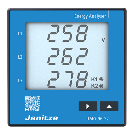
UMG 96-S2 www.janitza.com Design of the device 4.1 Front view - display Fig. Front view of UMG 96-S2 Pos. Designation Description Manufacturer logo Logo of the device manufacturer QR code Coded figure of the device web site from the manufacturer Device display See chap. -
Page 17: Rear View - Location Of The Connections
UMG 96-S2 4.2 Rear view - location of the connections Fig. Rear view of UMG 96-S2 Pos. Designation Description Protection class II (reinforced or double insulation) in accordance “Protection class” symbol with IEC 60536 (VDE 0106, Part 1). “Supply voltage” connection L/+ and N/-. -
Page 18: Labeling Of The Device - Rating Plate
UMG 96xxx 10H • 000 1234567 XXXX/XXXX Aux: 90..265V, 50/60Hz . 90..250V . 1,5VA 300V CAT III Made in Germany • www.janitza.com Fig. Rating plate Pos. Designation Description AC supply voltage in V Nominal frequency in Hz Operating data DC supply voltage in V... - Page 19 UMG 96-S2...
-
Page 20: Assembly
UMG 96-S2 www.janitza.com Assembly 5.1 Installation location Install the device in stationary and weather- protected front panels of switching cabinets in the interior. Insert the device ATTENTION Mounting brackets from the front with catch Property damage due to noncompliance with... -
Page 21: Network Systems
UMG 96-S2 Network systems Installation Network systems and maximum rated voltages Use the device for voltage measurement in TN and TT systems with the approved overvoltage according to DIN EN 61010-1/A1: category of 300 V CAT III (measurement voltage surge 4 kV). -
Page 22: Disconnectors
UMG 96-S2 www.janitza.com WARNING 230V/400V 50/60Hz Risk of injury due to electric voltage! 240V Serious personal injuries or death can occur 50/60Hz due to: · Touching live exposed or stripped cores. · Device inputs that are dangerous to touch. Before starting work, disconnect your... -
Page 23: Voltage Measurement
UMG 96-S2 Recommendation for overcurrent protection device for the line protection of the supply voltage: 6 - 16 A (Char. B, IEC-/UL approval) Fuse (UL/IEC-listed) Disconnect device Recommendation for the maximum number of (disconnector or circuit breaker) devices on one circuit breaker: ·... -
Page 24: Voltage Measurement Connection Versions
UMG 96-S2 www.janitza.com 7.5 Current measurement NOTE The device The device only determines the measured · is only approved for a current measurement values if voltage L1-N is greater than 20 Veff (4-conductor measurement) or voltage L1-L2 is using the current transformer. -
Page 25: Current Measurement Connection Versions
UMG 96-S2 Single phase 3-conductor system WARNING Risk of injury due to electric voltage on current transformers! High voltage spikes that are dangerous to touch can arise on current transformers that are operated open on the secondary side, which can result in serious injuries or even death. -
Page 26: Summation Current Measurement
UMG 96-S2 www.janitza.com 7.5.2 Summation current measurement For a summation current measurement via two current transformers, first set their total trans- formation ratio on the device (setting the current transformer ratios, see starting from chap. 12.4 on page 36). Example: The current measurement occurs via two current transformers. -
Page 27: Connection
UMG 96-S2 Connection 8.1 Connection to a PC 8.2 RS485 interface (serial interface) The following common connection methods are described for the communication of the derive The RS485 interface for this device is designed with a PC (with installed GridVis software). -
Page 28: Shielding
UMG 96-S2 www.janitza.com 8.3 Shielding 8.4 Termination resistors For connections via the interfaces, provide Terminate your cable at the start and end of a twisted and shielded cable and observe a segment with resistors (120 ohm, 0.25 W). the follow points for the shielding: The device does not contain an integrated ·... -
Page 29: Bus Structure
· devices with an activated bus terminator must be supplied with power. Fig. Representation of a bus structure Master Slave Slave Slave Repeater Slave Slave Slave Slave - Power supply necessary Master - e.g. UMG 604-PRO - Bus terminator switched on Slave - UMG 96-S2... -
Page 30: Communication Via The Rs485 Interface With The Modbus Rtu Protocol
Designation Hex Remark · Data from the parameter list and · Measured values from the Modbus address list. Device address UMG 96-S2, address = 1 Function Setting range of the device addresses: 1 .. 247 Byte counter Standard setting: Data 00hex = 00dec Standard setting for baud rate in kbps: 38.4... -
Page 31: Digital Output
UMG 96-S2 10. Digital output 10.3 Pulse value (parameter address 102) The device has an electrically isolated digital output, which outputs the active energy, reactive The pulse value specifies how much energy energy or apparent energy obtained as an S0 (Wh or varh) a pulse should correspond to. -
Page 32: Pulse Length (Parameter Address 106) And Pulse Pause
UMG 96-S2 www.janitza.com 10.4 Pulse length (parameter address 106) 10.5 Determining the pulse value and pulse pause Establishing the pulse length Pulse length Establish the pulse length according to the The pulse that is sent at the pulse output S0 requirements of the connected pulse receiver. -
Page 33: Operation And Button Functions
UMG 96-S2 11. Operation and button functions Max. value, HT/consumption Minimum value, NT/export Mean value Programming mode Summation measurement Phase conductor/phase conductor Password CT: Current transformer VT: Voltage transformer K1: Output 1 Fig.: Device display Export Key 1 Key 2 11.1 Operation... -
Page 34: Button Functions
UMG 96-S2 www.janitza.com 11.2 Button functions Display mode Programming mode Switch mode: press simultaneously Password Scroll Scroll Measured Measured Measured Program values values values menu 4 press press Measured Measured Measured Program values values values briefly briefly menu 3 Measured... -
Page 35: Parameter (Addresses) And Measured Value Display
UMG 96-S2 11.3 Parameter (addresses) and measured 11.3.3 Measured value display value display The device summarizes selected measured 11.3.1 Parameter (addresses) values in 3 measured value display profiles. The measured values appear in the display mode of All parameters required for the device, such as... -
Page 36: Configuration
UMG 96-S2 www.janitza.com 12. Configuration 12.1 Connecting the supply voltage To configure the device, connect the supply voltage. Observe the general safety instructions while doing so, as described in chap. „2. Safety“ on page 10. Password protection active The supply voltage level can be found on the rating plate of the device or in chap. -
Page 37: Programming The Current Transformer
UMG 96-S2 12.5 Programming the current transformer 12.6 Programming the voltage transformer 1. Switch into programming mode. 1. Switch into programming mode. 2. The symbols PRG for the programming 2. The symbols PRG for the programming mode and CT for the current transformer mode and CT for the current transformer appear. -
Page 38: Programming The Parameters
UMG 96-S2 www.janitza.com 12.7 Programming the parameters 12.7.2 Setting the baud rate (parameter address 001) 1. Switch into programming mode. 2. The symbol PRG for the programming mode For each device in a master/slave network via appears. the RS485 interface: 3. -
Page 39: Deleting Min. And Max. Values (Parameter Address 506)
UMG 96-S2 Averaging method 12.7.6 User password (parameter address 050) The exponential averaging method used In order to protect already programmed or achieves at least 95% of the measured value configured data, the device offers password after the set averaging time. -
Page 40: Deleting The Energy Counter (Parameter Address 507)
A harmonic is a harmonic vibration, the frequency of which is a whole multiple of a base frequency (mains frequency). The UMG 96-S2 requires a mains frequency of the voltage in the range of 45 to 65 Hz. The calculated harmonics of the voltages and currents relate to this mains frequency. -
Page 41: Phase Sequence
Normally a “right rotation field” exists. The phase order at the voltage Phase L3 measurement inputs is checked and displayed in the UMG 96-S2. Current harmonics Value The device only determines the phase sequence if supply voltage and measured voltages are Fig. -
Page 42: Commissioning
UMG 96-S2 www.janitza.com 13. Commissioning 13.1 Connecting the supply voltage · the device displays approx. 0 amperes in the short circuited current measurement inputs. · The supply voltage level for the device can · if necessary, adjust the current transformer be found on the rating plate or in chap. -
Page 43: Checking The Individual Powers
UMG 96-S2 13.8 Checking the individual powers If an incorrect phase conductor (phase) is assigned to a current transformer, the associated power is incorrectly measured and displayed. The phase conductor and current transformer are correctly assigned on the device if there is no voltage present between the phase conductor and the associated current transformer (primary). -
Page 44: Measured Value Display And Automatic Display Change Profile
UMG 96-S2 www.janitza.com 14. Measured value display and automatic display change profile 14.1 Measured value displays If a key is pressed between the automatic display change, the next measured value display stored in After a return of power, the device shows the first the profile appears. - Page 45 UMG 96-S2...
-
Page 46: Overview Of Measured Value Displays - Display Profile
UMG 96-S2 www.janitza.com 14.4 Overview of measured value displays - display profile 1-3 1 2 3 1 2 3 1 2 3 1 2 3 Measured values Mean values Max. values Min. values L1-N voltage L1-N voltage L1-N voltage L1-N voltage... - Page 47 UMG 96-S2 Measured values Mean values Max. values (ind) L1 reactive power L1 reactive power L1 reactive power L2 reactive power L2 reactive power L2 reactive power L3 reactive power L3 reactive power L3 reactive power 1 2 3...
- Page 48 UMG 96-S2 www.janitza.com 1 2 3 1 2 3 1 2 3 Min. value Max. value Measured value Frequency L1 Frequency L1 Frequency L1 Rotation field Rotation field Rotation field display display display 1 2 3 1 2 3 1 2 3...
- Page 49 UMG 96-S2 Measured value Measured value Measured value 1st harmonics 3rd harmonics 15th harmonics I L2 I L2 I L2 Measured value Measured value Measured value 1st harmonics 3rd harmonics 15th harmonics I L3 I L3 I L3 Max. value Max.
-
Page 50: Overview Of Automatic Display Change Profiles
UMG 96-S2 www.janitza.com 14.5 Overview of automatic display change profiles 1-3 Measured value NOTE Total reactive power Please note! · The measured value displays change depending on the set changeover time (parameter address 039). 1 2 3 · The display change profiles do not include... - Page 51 UMG 96-S2 Measured value 1st harmonics I L1 Measured value 1st harmonics I L2 Measured value 1st harmonics I L3...
-
Page 52: Connection Example
Data GND Funktionserde Functional ground UMG 96-S2 Digitaler Ausgang RS485 Digital output Versorgungsspannung Spannungsmessung Strommessung Power supply voltage Voltage measurement Current measurement N/- L/+ 230V/400V 50Hz Fig. Connection example for UMG 96-S2 1) UL/IEC approved fuse protection 2) Jumpers (external) - Page 53 UMG 96-S2...
-
Page 54: Service And Maintenance
UMG 96-S2 www.janitza.com 16. Service and maintenance 16.3 Device adjustment The device is subject to various safety tests prior to delivery and marked with a seal. If a device The manufacturer adjusted the devices before is opened, the safety tests must be repeated. -
Page 55: Error Messages
UMG 96-S2 17. Error messages 17.1 Warnings In the event of errors, the device has 3 types of error messages: Warnings are errors that can be acknowledged via key 1 or key 2. · Warnings. The recording and display of measured values ·... -
Page 56: Exceeding The Measurement Range
UMG 96-S2 www.janitza.com 17.4 Exceeding the measurement range 17.5 Measurement range exceedance parameter A measurement range exceedance · exists when at least one of the three voltage or A coded error description is in the measurement current measurement inputs are outside of the range exceedance parameter (address 600) in threshold values for the metering range. -
Page 57: Procedure In The Event Of Errors
UMG 96-S2 17.6 Procedure in the event of errors Possible error Cause Remedy No display External fuse for the power supply voltage Replace fuse. has tripped. No current display Measured voltage is not connected. Connect the measured voltage. Measurement current is not connected. -
Page 58: Technical Data
Relative humidity 0 to 90% RH Ambient conditions during operation Use the UMG 96-S2 in a weather-protected, stationary application. Protection class II in accordance with IEC 60536 (VDE 0106, Part 1). Operating temperature range K55, -10° C (14 °F) .. +55° C (131 °F) - Page 59 UMG 96-S2 Current measurement Rated current x/1 and x/5 A Metering range 0.005 .. 6 Arms Measurement range exceedance I > 7 Arms Crest factor (based on the rated current) Resolution 1 mA (display 0.01 A) at ../5 A 1/4 mA at ../1 A...
-
Page 60: Function Characteristics
UMG 96-S2 www.janitza.com Terminal connection capacity (serial interface) Single core, multi-core, fine-stranded 0.2 - 1.5 mm , AWG 28-16 Cable end sleeve (not insulated) 0.2 - 1.5 mm , AWG 26-16 Cable end sleeve (insulated) 0.2 - 1.5 mm , AWG 26-16 Tightening torque 0.2 - 0.25 Nm (1.77-2.21lbf in) - Page 61 UMG 96-S2...
-
Page 62: Parameter And Modbus Address List
UMG 96-S2 www.janitza.com 18.2 Parameter and Modbus address list NOTE The parameter list (table 1) contains the settings · A complete overview of the parameter list and for the correct operation of the device, such as the Modbus address list with explanations for the selected measured values can be found e.g. -
Page 63: Table 2 - Modbus Address List (Excerpt Of The Frequently Required Measured Values)
UMG 96-S2 18.4 Table 2 - Modbus address list (excerpt of the frequently required measured values) Modbus Address via Format RD/WR Unit Remark address display 19000 float Voltage, L1-N 19002 float Voltage, L2-N 19004 float Voltage, L3-N 19006 float... -
Page 64: Number Formats
• Comparator timer • S0 counter statuses • Min. / Max. / mean values (without the date and time) • Energy values • Configuration data is saved immediately. A detailed Modbus address and parameter list can be found at www.janitza.com... -
Page 65: Dimensional Drawings
UMG 96-S2 19. Dimensional drawings · All specifications in mm. · The figures serve as illustrations and are not true to scale. Rear view Side view max. 6 View from below Cut-out size +0,8 91,5... - Page 66 Janitza electronics GmbH Vor dem Polstück 6 35633 Lahnau, Germany Tel.: +49 6441 - 9642-0 e-mail: info@janitza.com info@janitza.com | www.janitza.com Subject to technical changes. The current status of the document can be found in the download area at www.janitza.com.
Need help?
Do you have a question about the UMG 96-S2 and is the answer not in the manual?
Questions and answers