Table of Contents
Advertisement
Quick Links
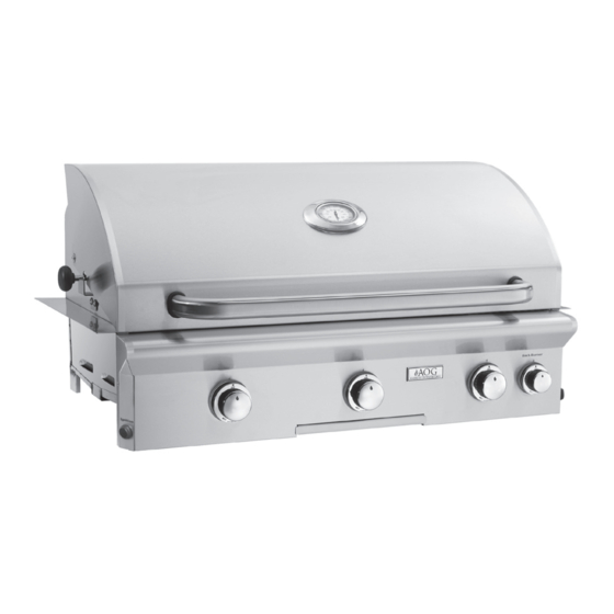
BUILT-IN OUTDOOR GAS GRILLS
24, 30, & 36 "L" Series
INSTALLATION AND
OWNER'S MANUAL
INSTALLER:
Leave these instructions with consumer.
CONSUMER:
Retain for future reference.
IMPORTANT:
READ THESE INSTRUCTIONS CAREFULLY BEFORE STARTING INSTALLATION OR USE.
DANGER:
IF YOU SMELL GAS
• Shut off gas to the appliance.
• Extinguish any open flame.
• Open lid.
• If odour continues, keep away from the
appliance and immediately call your gas
supplier or the fire department.
ONLY TO BE USED OUTDOORS
CODE AND SUPPLY REQUIREMENTS:
must conform with local codes or, in the absence of
local codes, with either the National Fuel Gas Code,
ANSI 2223.1/NFPA 54, or the Natural Gas and Propane
Installation Code, CSA B149.1, or the Propane Storage
and Handling Code, CSA B149.2, as applicable.
The outdoor cooking gas appliance and its individual
shut-off valve must be disconnected from the gas
supply piping system during any pressure testing of
that system at test pressures in excess of
kPa).
The outdoor cooking gas appliance must be isolated
from the gas supply piping system by closing its
individual manual shut-off valve during any pressure
testing of the gas supply piping system at test
pressures equal to or less than
Proper operation of your grill
requires prompt and periodic
maintenance. See the SERVICING
AND CLEANING section for details.
REV 5 - B - 2307140830
WARNINGS AND SAFETY CODES
:
Installation
1
/
psi (3.5
2
/
psi (3.5 kPa).
1
2
American Outdoor Grill • PO Box 4053 • La Puente, CA 91747
WARNING:
• Do not store or use gasoline or other
flammable liquids or vapours in the vicinity
of this or any other appliance.
• An LP cylinder not connected for use shall
not be stored in the vicinity of this or any
other appliance.
WARNING:
Improper installation, adjustment, alteration,
service, or maintenance can cause injury or
property damage. For proper installation,
refer to the installation instructions. For
assistance or additional information, consult
a qualified professional service technician,
service agency, or the gas supplier.
This appliance is designed as an attended
appliance. DO NOT leave this appliance burning
when unattended.
If an external electrical source is utilized, the outdoor
cooking gas appliance, when installed, must be
electrically grounded in accordance with local codes
or, in the absence of local codes, with the National
Electrical Code, ANSI/NFPA 70, or the Canadian
Electrical Code, Part I, CSA C22.1.
Keep any electrical supply cord and the fuel supply
hose away from any heated surfaces.
Cooking Grid U.S.
Patent Nos.
D857,453
D862,984
1
36" model shown
®
C
US
Certified to:
ANSI Z21.58
CSA 1.6
L-C2-437
Advertisement
Table of Contents

Related Manuals for AOG 24 L Series 30 L Series 36 L Series


Summary of Contents for AOG 24 L Series 30 L Series 36 L Series
- Page 1 BUILT-IN OUTDOOR GAS GRILLS 24, 30, & 36 "L" Series INSTALLATION AND OWNER’S MANUAL INSTALLER: Leave these instructions with consumer. 36" model shown CONSUMER: Retain for future reference. IMPORTANT: READ THESE INSTRUCTIONS CAREFULLY BEFORE STARTING INSTALLATION OR USE. WARNINGS AND SAFETY CODES DANGER: WARNING: •...
- Page 2 GRIL À GAZ EXTÉRIEUR INTÉGRÉ Séries 24, 30 et 36 "L" INSTALLATION ET LE MANUEL DU PROPRIÉTAIRE INSTALLATEUR: laissez ces instructions au consommateur. Modèle 36" illustré CONSOMMATEUR: À conserver pour référence future. IMPORTANT: LIRE ATTENTIVEMENT CES INSTRUCTIONS AVANT DE COMMENCER L'INSTALLATION OU L'UTILISATION. AVERTISSEMENTS ET CODES DE SÉCURITÉ...
-
Page 3: Table Of Contents
MODEL SPECIFICATIONS ����������������������������������������� MAIN BURNER REMOVAL �������������������������� BUILT-IN GRILL WIRING DIAGRAM ������ CONVERT GAS TYPE / CHECK BURNER ORIFICES �������������� AOG GRILL REPLACEMENT PARTS LIST AIR SHUTTER ADJUSTMENT / BURNER FLAME ����������������������������������������������������������� INSPECTION ����������������������� VALVE "LOW" SETTING ADJUSTMENT ������������������������������������������������� TROUBLESHOOTING ����������������������������������������������������������������... - Page 4 AVERTISSEMENTS Avertissements généraux : • Cet appareil est destiné à une utilisation en extérieur uniquement. Si l'appareil est entreposé à l'intérieur, retirez les bouteilles et gardez-les à l'extérieur. • Ne couvrez pas immédiatement l'appareil après utilisation. Laissez-le refroidir avant de le couvrir, de le déplacer ou de le ranger.
-
Page 5: Installation, Operation, And Safety Information
INSTALLATION, OPERATION, AND SAFETY INFORMATION 1. Wear gloves and use extreme caution whenever installing optimal performance. Adjust the air shutter as needed and handling this product and its accessories as certain to achieve proper flame pattern (see AIR SHUTTER ADJUSTMENT/BURNER FLAME INSPECTION components have sharp edges that can cause personal section, under SERVICING AND CLEANING for details ). -
Page 6: Gas Safety Information
GAS SAFETY INFORMATION WHEN OPERATING THIS GAS APPLIANCE, ALL INSTRUCTIONS AND WARNINGS MUST BE OBSERVED. FAILURE TO DO SO MAY RESULT IN A FIRE OR EXPLOSION CAUSING PROPERTY DAMAGE, BODILY INJURY, OR DEATH. WARNING This gas appliance and its enclosure MUST be plumbed and vented in accordance with local building and safety codes and should be approved by local code enforcement officials. -
Page 7: Safe Use & Maintenance Of Propane Gas Cylinders
SAFE USE & MAINTENANCE OF PROPANE GAS CYLINDERS IMPORTANT FOR YOUR SAFETY READ AND FOLLOW ALL WARNINGS PROVIDED WITH THE PROPANE-GAS CYLINDER. When operating this appliance with a propane-gas cylinder, these instructions and warnings MUST be observed. FAILURE TO DO SO MAY RESULT IN A SERIOUS FIRE OR EXPLOSION. For requirements related to ventilation, L.P. - Page 8 UTILISATION SÛRE ET ENTRETIEN DES CYLINDRES DE GAZ DE PROPANE IMPORTANT POUR VOTRE SÛRETÉ LISEZ ET SUIVEZ TOUS LES AVERTISSEMENTS ÉQUIPÉS DE VOTRE CYLINDRE DE GAZ DE PROPANE. En actionnant cet appareil avec un cylindre de gaz de propane ON DOIT observer ces instructions et avertissements. LE MANQUE DE FAIRE AINSI PEUT AVOIR COMME CONSÉQUENCE UNE INCENDIE OU UNE EXPLOSION SÉRIEUSE.
- Page 9 SAFE USE & MAINTENANCE OF PROPANE GAS CYLINDERS (Cont.) Important: Before using the unit, and after each time the cylinder is removed and reattached, check the hose for wear (see a.) and check all connections for leaks. Turn off the unit valves and open the main cylinder valve, then check connections with soapy water.
- Page 10 UTILISATION SÛRE ET ENTRETIEN DES CYLINDRES DE GAZ DE PROPANE (suite) Important: Avant d’employer le unité, et ensuite c h a q u e f o i s q u e l e c y l i n d r e e s t enlevé...
-
Page 11: Enclosure Requirements
ENCLOSURE REQUIREMENTS GFRC islands are available (for select models). They meet all enclosure and ventilation requirements. Contact your local dealer. For requirements regarding custom-built enclosures, see below. To ensure proper operation and safety, the enclosure MUST comply with the following: •... - Page 12 ENCLOSURE REQUIREMENTS (Cont.) Ventilation CORRECT FOR YOUR SAFETY, you must provide the openings specific to your gas type for replacement air and ventilation of the enclosure (in case of possible leakage from gas connections and L.P. cylinders as applicable, and for heat dissipation). See the following sections for ventilation requirements specific to your gas type.
- Page 13 ENCLOSURE REQUIREMENTS (Cont.) L.P. Cylinder Ventilation Requirements L.P. CYLINDER VENTILATION REQUIREMENTS: When an L.P. cylinder is used in the enclosure, the • Minimum 4 openings (2 at top & 2 at floor level) guidelines below MUST be followed: • 2 per adjacent wall - spaced at min. 90 degrees One side of the enclosure shall be left completely open to •...
- Page 14 ENCLOSURE REQUIREMENTS (Cont.) L.P. Cylinder Requirements (if applicable) (L.P. Cylinder When a propane (L.P.) cylinder is installed inside of the setups only) enclosure, the additional guidelines below MUST be followed. FAILURE TO DO SO MAY CAUSE DAMAGE Non-combustible Grill heat shield TO YOUR UNIT AND/OR PERSONAL INJURY.
- Page 15 ENCLOSURE REQUIREMENTS (Cont.) Cutout Dimensions Important: These cutout dimensions below are for non-combustible enclosures. If installing this grill in a combustible enclosure, the correct insulating liner must be used (and the cutout dimensions will differ). See Table 3. Refer to the instructions supplied with the liner for the correct cutout dimensions.
- Page 16 ENCLOSURE REQUIREMENTS (Cont.) ENCLOSURE REQUIREMENTS (Cont.) Substrate When adding any substrate to the enclosure front wall (including tiles, stone, etc.), consider the following: Substrate Behind Control Panel Substrate Alongside Control Panel Substrate + countertop "front to back" cutout Any additional substrate alongside the control panel does not need to be considered in Dim.
-
Page 17: Installation Requirements
INSTALLATION REQUIREMENTS Installation must be performed by a qualified professional service technician. Combustible overhead construction: This unit is designed for outdoor use only. DO NOT use this Exhaust hood required unit inside a building, garage, or enclosed area. DO NOT install Non-combustible this unit in or on a recreational vehicle or boat. -
Page 18: Rear Wall Clearances
INSTALLATION REQUIREMENTS (Cont.) REAR WALL CLEARANCES Non-combustible For the minimum clearances between the unit and rear walls, your setup must fall within one (or more) of the following: Min. A. Clearance between unit and strictly non-combustible 4" rear wall (i.e. brick wall, see Fig. 18-1) (Clearance required for •... -
Page 19: Control Panel Clearances
INSTALLATION REQUIREMENTS (Cont.) CONTROL PANEL CLEARANCES • The control panel MUST have a minimum side clearance of 6" from any obstructions/side walls. See Fig. 19-1. (To allow for access to side switches and control panel removal.) • The control panel MUST remain removable for servicing (see CONTROL PANEL REMOVAL section). -
Page 20: Diagrammatical Representations Of Outdoor Areas
DIAGRAMMATICAL REPRESENTATIONS OF OUTDOOR AREAS The following figures are diagrammatical representations of outdoor areas, as defined in Clause 4.25.3. See INSTALLATION REQUIREMENTS section. Fig. 20-2 Outdoor area - Example 2 Fig. 20-1 Outdoor area - Example 1 Both ends open 30% or more of the horizontal periphery of the enclosure is open and unrestricted... -
Page 21: Electrical Safety
ELECTRICAL SAFETY • To protect against electric shock, do not immerse cord or plugs in water or other liquid. • Unplug from the outlet when not in use and before cleaning. Allow to cool before putting on or taking off parts. •... -
Page 22: Model Specifications
Grill complete maintenance kit model # MCK-1 MCK-1 MCK-1 If applicable, not included † If installing this grill in a combustible enclosure, the correct AOG insulating liner must be used. Consult liner instructions for counter cutout dimensions and installation. Table 3 - Grill Supporting Products... -
Page 23: Built-In Grill Wiring Diagram
MODEL SPECIFICATIONS (Cont.) Height Width Depth (Front to (Top to bottom) (Left to right) back) Model Upper hanger to top Control panel Hanger to Maximum (with oven) width hanger depth Open Closed 24" 22" " 28" 25" " 22" " 34"... -
Page 24: Aog Grill Replacement Parts List
AOG GRILL REPLACEMENT PARTS LIST IMPORTANT This AOG oven and backburner (if equipped) are fully pre-assembled and tested at the factory. 24" Model shown DO NOT attempt to remove the oven and backburner from the barbecue prior to or during installation or damage to the connecting gas line and igniter wiring may occur. - Page 25 AOG GRILL REPLACEMENT PARTS LIST (Cont.) 24" 30" 36" Item Description Part No. Qty. Part No. Qty. Part No. Qty. Stainless cooking grid (set of 2 or 3) 24-B-11A 30-B-11A 36-B-11A Vaporizer panel (set of 2 or 3) 24-B-05-2 30-B-05-3...
-
Page 26: Installation
INSTALLATION It is not required to remove the control panel or knobs to install this unit. DO NOT lift the unit from the control panel when installing. BUILD / CONSTRUCT ENCLOSURE GFRC islands are available (for select models). They accommodate your grill and side cooker/accessories. Build the enclosure per the instructions supplied with the unit. - Page 27 INSTALLATION (Cont.) INSTALL POWER SUPPLY BOX Locate power supply If side cookers are to be installed and will be powered Route wire harness extension downward using the same grill power supply, instead refer to the Mount power supply POWER SUPPLY / WIRE HARNESS CONNECTIONS Connect cord to power source section of the owner's manual included with the side cooker for power supply installation.
-
Page 28: Connect Gas Supply
INSTALLATION (Cont.) CONNECT GAS SUPPLY To Connect To Propane Cylinder: Flex connector Flex connector Read the safety warnings and follow the instructions in the (coming from (coming from section SAFE USE AND MAINTENANCE OF PROPANE grill) grill) GAS CYLINDERS. Note: When a propane cylinder is installed inside Regulator Regulator of the enclosure, the guidelines found in... -
Page 29: Install Vaporizer Panels
INSTALLATION (Cont.) INSTALL VAPORIZER PANELS Place the vaporizer panels directly onto the studs on the burners. See Fig. 29-1. The panels allow heat from the burners to be evenly distributed throughout the cooking area. The panels are stainless steel and will heat and cool quickly, making your grill very responsive to the changes you specify in grill temperature. -
Page 30: Identification Of Grill Controls
IDENTIFICATION OF GRILL CONTROLS Right main burner Backburner control knob control knob Ignition (if equipped) switch Left main burner Control panel control knob screw(s) Drip tray Light switch* The light switch is push button operated, and is located on the right side of the control panel. - Page 31 USING THE GRILL BEFORE INITIAL USE Ensure that: • the unit has been properly installed and leak tested by a qualified professional service technician and as instructed in this manual. • you have read and understand all of the information in this manual. BEFORE EACH USE Ensure that: •...
- Page 32 ALLUMAGE DES INSTRUCTIONS (D’ALLUMAGE) Lisez toutes les instructions avant l’allumage, et suivez ces instructions chaque fois vous lumière le unité. ÉCLAIRAGE ÉLECTRONIQUE ÉCLAIRAGE MANUEL Note: Le unité doit être relié à la puissance 120VAC pour L’éclairage électronique exige une batterie installée Note: ATTENTION: Attendez toujours cinq (5) minutes le gaz l’éclairage électronique.
-
Page 33: Lighting (Ignition) Instructions
LIGHTING (IGNITION) INSTRUCTIONS Read all instructions before lighting, and follow these instructions each time you light the unit. ELECTRONIC LIGHTING MANUAL LIGHTING ELECTRONIC LIGHTING Note: Electronic lighting requires an installed 9-volt CAUTION: Always wait five (5) minutes for gas to Note: This unit must be connected to 120VAC power battery with a good charge. -
Page 34: Rotisserie Instructions (If Equipped)
ROTISSERIE INSTRUCTIONS (IF EQUIPPED) CAUTION: WHEN USING THE BACKBURNER; 3. Slide the left spit prong onto the rod (and tighten), KEEP THE OVEN LID CLOSED TO the meat onto the rod and into the prong, followed by PREVENT HEAT LOSS, PROVIDE the right spit prong onto the rod and into the meat. -
Page 35: Servicing And Cleaning
Clean tray in a soapy water solution if needed. For tough deposits, a copper pad can be used. Rinse and dry completely. 3. Cover your grill: Once the grill is dry and cool, cover your grill with an AOG protective cover (not included). - Page 36 Protecting Your Grill An optional AOG protective cover will protect your grill when not in use. Install the cover on a cool and dry grill. DO NOT cover a damp grill. During high humidity or after rainy conditions, remove the cover to dry trapped moisture if present. (If the cover is installed over a damp grill it can cause surface rust.)
-
Page 37: Replacing Halogen Bulbs
SERVICING AND CLEANING (Cont.) REPLACING HALOGEN BULBS 5. Wearing a pair of gloves, reach into the fixture, gently grab the bulb, and pull it straight out of the Your grill is engineered with the conveniences of fixture so that the two pins at the base of the bulb electrical power for illuminating and igniting the grill. -
Page 38: Control Panel Removal
SERVICING AND CLEANING (Cont.) CONTROL PANEL REMOVAL Remove bezel 1. Turn the control knobs to the OFF position and turn off the gas supply to the grill. 2. Turn off the light switch and disconnect the unit from the power source. 3. -
Page 39: Fuse Replacement
SERVICING AND CLEANING (Cont.) FUSE REPLACEMENT If the unit is connected to the power supply but the ignition system and interior oven lights are not functioning, fuse replacement may be required. 1. Ensure the knobs are in the OFF position, the gas supply is turned off, and the light switch is off. -
Page 40: Convert Gas Type / Check Burner Orifices
SERVICING AND CLEANING (Cont.) CONVERT GAS TYPE / CHECK BURNER Convert Gas Orifices ORIFICES When converting the grill to a different gas type, each burner’s orifice must be replaced with the WHEN CONVERTING TO A NEW GAS TYPE, THE corresponding orifice for the new gas. ENCLOSURE MUST HAVE PROPER VENTILATION See Table 2 in the MODEL SPECIFICATIONS section to FOR THE NEW GAS TYPE. - Page 41 SERVICING AND CLEANING (Cont.) Valve Burner Orifice Fig. 41-1 - Main burner orifice diagram 4. Replace burners (See BURNER REMOVAL section). Note: It is critical to the continued safe functioning of the burners that the orifices are centered and completely inside the burner gas inlets. 5.
- Page 42 SERVICING AND CLEANING (Cont.) Convert/Check Infrared Burner Orifice 5. Replace the infrared burner over the orifice fitting, sliding it forward, from behind the forward fire wall, (burner sold separately) so the orifice is centered inside the burner gas inlet, Note: It may be necessary to remove the rotisserie and set it gently onto the burner support.
-
Page 43: Air Shutter Adjustment / Burner Flame Inspection
SERVICING AND CLEANING (Cont.) AIR SHUTTER ADJUSTMENT / BURNER FLAME INSPECTION Main Burner Flames: Important: Air shutters are preset at the factory (see • blue • quiet Table 2 in MODEL SPECIFICATIONS). • stable • touching burner However, gas conversion, altitude, or other local conditions may make it necessary to adjust the air shutters. -
Page 44: Valve "Low" Setting Adjustment
SERVICING AND CLEANING (Cont.) VALVE "LOW" SETTING ADJUSTMENT Stability of the "low" setting on all burners may vary due to (Manifold) wind direction, appliance configuration, and position. If your burner goes out when set on low, the valve "low" setting needs adjustment. -
Page 45: Troubleshooting
TROUBLESHOOTING If you have trouble with the unit, please use this list to identify the problem. By trying one or more of the solutions to the possible cause, you should be able to solve the problem. If this list does not cover your present problem, or if you have other technical difficulties with the unit, please contact your local dealer. -
Page 46: Warranty
WARRANTY AMERICAN OUTDOOR GRILL LIMITED WARRANTY ® American Outdoor Grill warrants your grill to be free from defects in material and workmanship. American Outdoor Grill stainless-steel burners are warranted for as long as the original purchaser owns them -- LIFETIME. All other American Outdoor Grill parts are warranted for TEN (10) YEARS.
Need help?
Do you have a question about the 24 L Series 30 L Series 36 L Series and is the answer not in the manual?
Questions and answers