Table of Contents
Advertisement
Quick Links
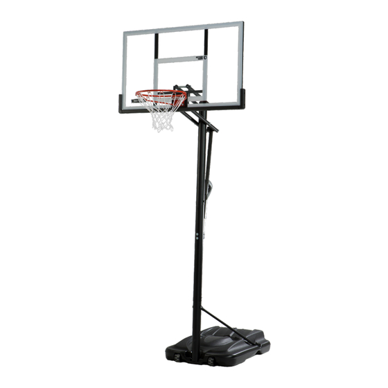
ACTION GRIP
BASKETBALL SYSTEM
MODEL 91330
BEFORE ASSEMBLY:
• Decide with what to fi ll the base
(sand is recommended)
• At least 2 people recommended for setup
IMPORTANT, RETAIN FOR FUTURE REFERENCE: READ CAREFULLY
TOOLS REQUIRED
1/2" (≈13mm), 7/16" (≈12mm),
9/16" (≈15mm), 3/4" (≈19mm)
(x2)
(x1)
(x1)
QUESTIONS?
CONTACT LIFETIME CUSTOMER SERVICE:
Dial 1-800-225-3865
™
3/16" (≈5mm)
1/2" (≈13mm)
(included)
(x1)
(x1)
(x1)
Live Chat:
www.lifetime.com/customerservice/home
(Click on "LIVE CHAT" tab)
ASSEMBLY INSTRUCTIONS
Pour le français, voir la page 2. Para el español, ver la página 3.
(x2)
(x1)
375 lb (≈170 kg)
(x1)
(x1)
(x1)
For Customer Service in Mainland Europe
and the United Kingdom,
E-mail: csinternational@lifetime.com
TABLE OF CONTENTS
Icon Legend.........................................................4
Warnings & Notices..............................................5
Pole Assembly......................................................6
Pole-to-Base Assembly.......................................11
Backboard-to-Rim Assembly...............................15
Backboard-to-Pole Assembly..............................19
Handle Assembly................................................24
Final Assembly...................................................31
Maintenance.....................................................37
Warning Sticker..................................................38
Registration......................................................39
Warranty..........................................................40
Model Number: 91330
Product ID:
Advertisement
Table of Contents

Related Manuals for Lifetime ACTION GRIP 91330


Summary of Contents for Lifetime ACTION GRIP 91330
-
Page 1: Table Of Contents
Warning Sticker..........38 Registration............39 Warranty............40 (x1) (x1) (x1) (x1) Model Number: 91330 QUESTIONS? CONTACT LIFETIME CUSTOMER SERVICE: Product ID: Dial 1-800-225-3865 Live Chat: For Customer Service in Mainland Europe and the United Kingdom, www.lifetime.com/customerservice/home E-mail: csinternational@lifetime.com (Click on “LIVE CHAT” tab) -
Page 2: Icon Legend
ICON LEGEND • Indicates special heed should be taken when reading. • Indicates the parts required for a section. • Indicates no parts are required for a section. • Indicates the hardware to be used for a section. • Indicates no hardware required for a specifi c page or section. •... -
Page 3: Warnings & Notices
WARNINGS & NOTICES SAFETY INSTRUCTIONS FAILURE TO FOLLOW THESE WARNINGS MAY RESULT IN SERIOUS INJURY OR PROPERTY DAMAGE AND WILL VOID WARRANTY. Owner must ensure that all players know and follow these rules for safe operation of the system. To ensure safety, do not attempt to assemble this product without following the instructions carefully. Check entire box and inside all packing material for parts and/or additional instruction material. - Page 4 POLE ABE (x2) AAF (x2) ADS (x2) ABZ (x2) ABR (x2) CIH (x2) ABB (x2) Metal parts ALH (x1) ALL (x1) ALF (x1) Warning sticker • The bottom pole (ALE) has been designed with an indent at one end. ALE (x1) Scrap wood 9/16"...
- Page 5 9/16" (≈14 mm) (x2) ABE (x2) ABB (x2) ABR (x2) AAF (x2) • Secure the pole bracket (ALL) to the middle pole (ALF) with the hardware as indicated. Small holes Large holes Warning sticker...
- Page 6 ADS (x1) CIH (x1) • Align the hole in the bottom of the top pole (ALH) • Strike the end of the pole assembly on a piece of scrap wood or cardboard 5–6 times. with the slot in the top of the middle pole (ALF). •...
- Page 7 ADS (x1) CIH (x1) • Continue seating the poles until the length of the • Secure the middle pole to the bottom pole (ALE) using assembly is no longer than 83 1/2" (≈212 cm). the same method as step 1.2. •...
- Page 8 ABZ (x2) • Secure the poles with self-drilling screws (ABZ). • Again, strike the end of the pole assembly on a piece of scrap wood or cardboard 5–6 times. Ensure the slots in the poles are covered before • THE SCREWS (ABZ) ARE DESIGNED TO DRILL INTO THE continuing with the assembly.
-
Page 9: Pole-To-Base Assembly
POLE-TO-BASE DRZ (x1) BTS (x1) EEO (x2) AAE (x2) ABD (x4) AAO (x2) Metal parts AJD (x1) ALI (x2) Plastic parts AMU (x2) AJN (x1) AJM (x1) 3/16 in/po (≈5 mm) 1/2 in/po (≈13 mm) (x2) (x2) (x1) - Page 10 • If you have trouble with this section, scan the code below to view a video on on its assembly. http://go.lifetime.com/actiongripsection2 • Screw the base cap (AJN) onto the base (AJM) as indicated. Rubber gasket • Make sure the rubber gasket is inside the base cap.
- Page 11 AAE (x2) AAO (x2) ABD (x4) • Slide the axle (AJD) through one of the wheels (AMU) and into the base as indicated. Have one adult position the bottom pole (ALE) within the base as shown (with the lip at the bottom of the pole facing outward). Finally, insert the axle through the bottom pole and into the other side of the base and through the other wheel.
- Page 12 3/16" (≈5mm) (x2) 1/2" (≈13 mm) (x2) DRZ (x1) BTS (x1) • Attach the pole braces (ALI) to the bottom pole (ALE) with the hardware indicated. • Tip the system forward and rest the pole on the ground. Do not stand the system up until it is fi lled with either sand or water later in the assembly.
-
Page 13: Backboard-To-Rim Assembly
BACKBOARD-TO-RIM DFE (x4) AAM (x2) AAA (x4) AAV (x2) AAJ (x2) ABD (x2) ABK (x4) ABF (x2) APZ (x1) AOW (x1) AJW (x2) Metal parts Plastic parts AJI (x1) ALX (x1) DFD (x1) ALD (x1) AMY (x2) 7/16" (≈11mm) 1/2" (≈13mm) 9/16"... - Page 14 1/2" (≈13mm) (x2) (x1) AAM (x2) ABD (x2) AAJ (x2) ABF (x2) • Insert two bolts (AAM) with washers (ABD) and rubber washers (ABF) through the holes indicated in the back of the rim (ALX) as shown. Secure the hardware with two T-nuts (AAJ). •...
- Page 15 1/2" (≈13mm) (x2) ABK (x2) APZ (x1) • Place the backboard face down onto a table, box or similar. Secure the rim (ALX) and plastic guard (ALD) to the backboard (AJI) with the hardware indicated.
- Page 16 7/16" (≈11mm) 1/2" (≈13mm) 9/16" (≈14mm) (x2) AOW (x1) DFE (x4) ABK (x2) AAV (x2) AAA (x4) AJW (x2) • Attach the backboard brackets (AMY) to the backboard using the hardware indicated. 9/16" (≈14 mm) (x2) • Turn the backboard assembly over. Thread the jam nuts (AAV) onto each end of the U-bolt (APZ) as far as they will go. Slide the compression springs (AJW) onto the U-bolt, and place the spring retainer plate (AOW) over the compression springs.
-
Page 17: Backboard-To-Pole Assembly
BACKBOARD-TO-POLE 7 5/8 in/po (≈19cm) GBU (x2) ABN (x8) AAX (x4) 7 1/16 in/po (≈18cm) AAD (x2) HMP (x2) 7 1/2 in/po (≈19cm) ABB (x1) DFC (x1) Metal parts AKC (x2) AJY (x2) AKB (x2) 3/4" (≈19 mm) 9/16" (≈14 mm) (x2) (x2) (x1) - Page 18 3/4" (≈19 mm) (x2) 7 5/8 in/po (≈19cm) GBU (x1) AAX (x1) ABN (x2) HMP (x1) • Attach the short extension arms (AKC) to the backboard brackets in the location shown with the hardware indicated. Secure only by hand at this point. A centerlock nut requires some effort to thread onto a bolt.
- Page 19 3/4" (≈19 mm) (x2) 7 5/8 in/po (≈19cm) 7 1/2 in/po (≈19cm) 9/16" (≈14 mm) (x2) GBU (x1) DFC (x1) ABB (x1) ABN (x2) AAX (x1) HMP (x1) • Attach the ends of the long extension arms (AKB) that only have one hole to the backboard brackets in the location shown with the hardware indicated.
- Page 20 3/4" (≈19 mm) (x2) 7 1/16 in/po (≈18cm) AAD (x1) AAX (x1) ABN (x2) • Attach both counterbalance springs (AJY) to the hex bolt (DFC) as indicated. • Lay the backboard assembly next to the pole assembly. Rest the rim on cardboard to prevent scratching. Then secure the short extension arms (AKC) to the top pole (ALH) with the hardware indicated.
-
Page 21: Parts Identifier
PARTS IDENTIFIER This page intentionally left blank... - Page 22 PARTS IDENTIFIER Metal parts Warning sticker ALH (x1) ALF (x1) ALE (x1) AJX (x2) ALL (x1) AMY (x2) AKC (x2) AKB (x2) AJD (x1) AKQ (x1) ALB (x1) ALX (x1) AJQ (x1) ALM (x1) AJY (x2) AJS (x1) CNJ (x1)
- Page 23 PARTS IDENTIFIER Plastic parts AKZ (x1) AJM (x1) AKI (x1) AJQ (x1) BAA (x1) BAB (x1) ALM (x1) CNJ (x1) AJS (x1) AMU (x2) ALD (x1) AMN (x1) AJN (x1) AKP (x1)
- Page 24 PARTS IDENTIFIER This page intentionally left blank...
- Page 25 3/4" (≈19 mm) (x2) 7 1/16 in/po (≈18cm) AAD (x1) AAX (x1) ABN (x2) • Secure the long extension arms (AKB) to the top pole (ALH) with the hardware indicated. • Tighten nuts until they are fl ush with the end of the bolts.
- Page 26 HANDLE 7 1/16 in/po (≈18cm) (Not actual length) ABO (x2) AAD (x1) APS (x1) 7 in/po (≈18cm) 7” ACY (x2) AAC (x1) (Not actual length) AAZ (x1) AQI (x1) ADR (x2) AEA (x2) AAN (x1) ABB (x1) AAX (x1) Plastic parts Metal parts AKQ (x1) CNJ (x1)
- Page 27 ADR (x2) AEA (x2) AQI (x1) APS (x1) • Attach the lock tab (APS) to the trigger (AMN) with • Insert the trigger assembly into the handle (AKI) as the hardware shown, and slide the trigger spring shown. The lock tab (APS) will fi t into the bottom (AQI) onto the trigger in the location shown.
- Page 28 ACY (x2) • Attach the handle assembly to the outer tube (ALB) with the hardware • Attach the outer tube bushing (CNJ) to shown. The lock tab (APS) will fi t into the notch on the outer tube. the outer tube (ALB). •...
- Page 29 1/2" (≈13 mm) (x2) AAC (x1) AAN (x1) • While squeezing the trigger (AMN), insert the notched end of the inner channel (AKQ) into the outer tube (ALB) as shown. Slide the inner channel into the outer tube until the 10' mark has been reached, then release the trigger so it clicks into place.
- Page 30 3/4" (≈19 mm) (x2) 7 1/16 in/po (≈18cm) AAD (x1) ABO (x2) (Not actual length) AAX (x1) (Non illustré à la longueur réelle) (No está ilustrado al tamaño real) • Secure the outer tube (ALB) to the long extension arms (AKB) with the hardware indicated. •...
- Page 31 9/16" (≈14 mm) (x2) 7 in/po (≈18cm) 7” (Not actual length) ABB (x1) AAZ (x1) 5.10 • Insert the hex bolt (AAZ) through the holes in the short extension arms (AKC) that are closest to the pole. Secure the bolt to the short extension arms with the centerlock nut (ABB).
- Page 32 5.12 • Raise the backboard to the highest position. Use the closed end of a wrench to stretch the spring (AJY) up and over the hex bolt (AAZ). Repeat this step to hook the end of the other spring up and over the bolt.
-
Page 33: Final Assembly
FINAL ASSEMBLY ADP (x10) Plastic parts AJQ (x1) AKZ (x1) BAA (x1) BAB (x1) WARNING For safety reasons, we recommend that sand be used instead of water to fill the Base. If a leak develops, water could run out unnoticed, allowing the system to fall over, resulting in serious personal injuries or property damage. - Page 34 (x1) ADP (x10) • Remove the plastic fi lm from the backboard (AJI). • Attach the center frame pad (AJQ) and corner frame pads (BAA and BAB) to the backboard in the location shown with the hardware indicated. Make sure that the center frame pad is centered on the metal piece of the backboard as indicated. •...
- Page 35 (x1) 375 lb. (≈170 kg) 6.3a • Two adults are required to complete assembly. To prevent serious injuries, the pole should be held down by one adult at all times while the base is being fi lled. • OPTION a: Filling the base (AJM) with sand. Sand is recommended. (375 lb of sand required) 1.
- Page 36 (x1) 6.3b • Two adults are required to complete assembly. To prevent serious injuries, the pole should be held down by one adult at all times while the base is being fi lled. • OPTION b: Filling the base (AJM) with water. Sand is recommended. 1.
- Page 37 • Attach the net (AKZ) to the rim (ALX). • If a replacement net is needed, please call our Customer Service Department. Our nets are shorter than average to reduce the risk of entanglement.
-
Page 38: Maintenance
MAINTENANCE The life of your basketball system depends on many variables. The climate, exposure to corrosives such as salt, pesticides, or herbicides, and excessive use or misuse can all contribute to pole failure, which may cause property damage or personal injury. Check your basketball system frequently for loose hardware, excessive wear, and signs of corrosion. -
Page 39: Warning Sticker
à l’anneau, au panneau ni aux leviers sous peine d’endommager elevación, ya que esto puede dañar el sistema y anular la garantía. l’équipement et d’annuler la garantie. Lifetime Products, Inc., Clearfield, UT 84016 www.lifetime.com # 1180194 1-800-225-3865... -
Page 40: Registration
. And you can rest assured that Lifetime will not sell or provide your personal data to other third parties, or ® ® allow them to use your personal data for their own purposes. We invite you to read our privacy policy at www.lifetime.com REGISTER today! - Page 41 NOTES...
- Page 42 NOTES...
- Page 43 2. This warranty is nontransferable and is expressly limited to the repair or replacement of defective product. If the product is defective within the terms of this warranty, Lifetime Products, Inc. will repair or replace defective parts at no cost to the purchaser.
- Page 44 ® ENHANCE YOUR LIFETIME PURCHASE BY ADDING ACCESSORIES OR OTHER GREAT PRODUCTS To purchase accessories or other Lifetime products, visit us at: ® www.lifetime.com Or dial 1-800-424-3865 www.lifetime.com 1232859 11/17/2023...
Need help?
Do you have a question about the ACTION GRIP 91330 and is the answer not in the manual?
Questions and answers