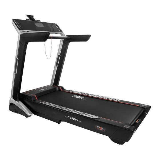
Christopeit Sport TM 5000S Assembly And Exercise Instructions
Hide thumbs
Also See for TM 5000S:
- Assembly and exercise instructions (44 pages) ,
- Assembly and exercise instructions (52 pages)

Related Manuals for Christopeit Sport TM 5000S


Summary of Contents for Christopeit Sport TM 5000S
- Page 1 Heimsport-Trainingsgerät Elektrisches Laufband Montage- und Bedienungsanleitung fu r Bestell-Nr. 1840A Assembly and exercise instructions for Order No. 1840A...
-
Page 2: Wichtige Empfehlungen Und Sicherheitshinweise
Inhaltsu bersicht Contents Page 22 1. Wichtige Empehlungen und Sicherheitshinweise Seite 2. Montageanleitung mit Explosionsdarstellungen Seite 3. Wartung, Garantiebestimmungen Seite 4. Benutzung der Smartphone/Tablet-Halterung Seite 5. Computeranleitung, Sto rungsbeseitigung Seite - 17 6. Trainingsanleitung, Warm up Seite 18 7. - Page 3 Montageanleitung Legen Sie alles u bersichtlich au den Boden und kontrollieren Sie die Vollza hligkeit anhand der Montageschritte. Einig Schrau- ben benden sich bereits an den Montagestellen au zwecks einacher Zuordnung. Die Montagezeit betra gt ca. 40min. Schritt 1: 1.
- Page 4 Schritt 4: 1. Fu hren Sie den Pulsgri (6) mit Hile einer zweiten Person zu den Stu tzrohren links und rechts (3L+R) und verbinden Sie die Stecker der Pulskabel (97) mit den Pulsverbindungskabeln 1 (98). 2. Stecken Sie den Pulsgri (6) vorsichtig in die Stu tzrohre (3L+R) ein, ohne dabei Kabel einzuquetschen, sodass die Beesti- gungsbohrungen u ...
- Page 5 Schritt 6: 1. Stecken Sie die Seitenverkleidungen links und rechts (30L+R) an die Stu tzrohre links und rechts (3L+R) und sichern Sie diese an den Halterungen links und rechts (12L+R) mittels den Schrauben 4x16 (75). 2. Stecken Sie dann die Innenabdeckungen links und rechts 31L+R) an die Halterungen (12L+R) und sichern Sie diese mit- tels der Schrauben (75).
- Page 6 Ein- / Ausklappen und transportieren 2. Platz sparend einklappen und Standortwechsel: Heben Sie den Laurahmen an Position „A“ an und klappen des Laubandes Sie das Lauband durch Anheben hochkant zusammen bis der Sicherungsknop (15) einrastet. Durch vollsta ndiges Einklappen 1.
- Page 7 Anmerkungen zur Wartung und Einstellung 1. Pfegen der Laufa che: Damit das Lauband dauerhat leicht und gut la ut, sollte immer nach 50 Betriebsstunden die Unterseite der Laua che, welche au dem Gleitbrett liegt au Ihre Gleita higkeit gepru t werden und gg.
- Page 8 Benutzung der Smartphone/Tablet-Halterung Ausklappen der Halterung: Bauteil Beschreibung Menge Halteklammer Auszug Ablage Smartphone/Tablet Schritt 1: Ziehen Sie hinter dem Computer an der Halterklammer (A) die Ablage (C) hoch, sodass sich diese mit dem Auszug (B) komplett herausschiebt. Schritt 2: Klappen Sie die Halteklammer (A) au und schieben Sie diese et- was nach links um die augeklappte Position zu arretieren.
- Page 9 Computeranleitung TM 5000S (Hinweis: Augrund der optionalen Mo glichkeiten ko nnen Funktionen und Beschreibungen von der sich darstellenden Situation etwas abweichen.) 1. Anzeigen Symbol u r Steigungsstue und Verbrauchsanzeige in Kcal Symbol Steigungsstue leuchtet = Steigungsstue wird angezeigt;...
- Page 10 2.2 Media-Funktionstasten: Lautsprechersymbol mit geringe Schalldruck: Verringert die Lautsta rke. Lautsprechersymbol mit gro ßerem Schalldruck: Erho ht die Lautsta rke. Wiedergabe/Pause: Startet oder stoppt die Hintergrundmusik/Video. Zuru ck: Wa hlt das vorherige Lied/Video aus. Vorwa ...
- Page 11 Dru cken der Stop-Taste beendet/pausiert das Programm und das Lauband verringert die Geschwindigkeit bis die Laua che steht. Es erscheint ein Pause Symbol im Display und es besteht die Mo glichkeit durch Dru cken der Start-Taste das Programm ortzusetzen oder durch Dru ...
- Page 12 Wettkampprogramme Dru cken Sie die “ ” -Taste 4 mal, um zum ersten Wettkampprogramm 3,0km zu gelangen. Mit jedem weiteren Dru cken der “ ”-Taste erscheinen die weiteren Wettkampprogramme 5.0km, 10.0km, 15.0km, 21,1km (Halbmarathon) und 42,19km (Marathon). Nutzer C ist Anzeige der Enternung das System in % u ...
- Page 13 U bersicht von Geschwindigkeit und Steigung der 24 Trainingsprogramme Die Trainingszeit der 24 Trainingsprogramme ist Die Trainingszeit der 24 Trainingsprogramme ist Balken augeteilt in 10 Balken Balken augeteilt in 10 Balken Õ Õ Programm Programm km/h km/h Steigungs- ISteigungs- stufe stufe km/h...
- Page 14 Individuelle Benutzerprogramme U1-U3 Durch Dru cken der “ ”-Taste gelangen Sie nach den 24 Trainingsprogrammen zu den 3 individuellen Benutzerprogramme (U1-U3). Hier ko nnen Sie Ihr eigenes Trainingsprofl einstellen, welches dauerhat gespeichert bleibt oder bei Bedar u berschrieben werden kann. Vera ...
- Page 15 BMI-Berechnung Durch Dru cken der “ ” -Taste gelangen Sie nach den 24 Trainingsprogrammen, den 3 individuellen Benutzerprogramme (U1-U3) und den Pulspro- grammen HP1/HP2 zu dem BMI Rechner. Geben Sie nacheinander Ihre perso nlichen Daten wie Geschlecht, Alter, Gro ße und Gewicht mittels der +/- Tasten ein und besta ...
- Page 16 Einstellungsmo glichkeiten/Inormation des Displays Inormation zur Wartung der Laua che mit Silicon-O l. Alle 300km werden Sie durch diesen Hinweis daran erinnert, dass eine Laua chen-Wartung durchgeu hrt werden muss. Siehe Rubrik: Pegen der Laua che. Der Hinweis kann durch Dru ...
- Page 17 Fehlercodes und Fehlerdiagnose Bei Funktionssto rungen kann nebenstehende Auistung von Fehlermeldungen eine Hile u r versierte Personen sein. Grundsa tzlich gilt, dass elektrische Reparaturarbeiten nur unter Einhaltung der einschla gigen Sicherheitsvorschriten durchzuu hren sind. Na here Inormationen und Hilestellung bei Funkti- onssto ...
- Page 18 Trainingsanleitung Um spu rbare ko rperliche und gesundheitliche Verbesserungen zu erreichen, Weitere Inormationen zum Thema Auwa rmu bungen, Dehnungsu bungen mu ssen u r die Bestimmung des erorderlichen Trainingsauwandes die oder allgemeine Gymnastiku bungen fnden Sie in unserem Downloadbereich unter www.christopeit-sport.com olgenden Faktoren beachtet werden: 4.
- Page 19 Stu ckliste - Ersatzteilliste • Ausklappautomatik Sot-Drop-System u r ein leises und sicheres herablassen der Laufa che TM 5000S Best.-Nr. 1840A • 4 Transportrollen u r einen bequemen Standortwechsel • Geeignet bis zu einem Ko rpergewicht von max. 150 kg Technische Daten: Stand: 01. 07. 2019 • Abmessung der Laufa che: ca. L 141 x B 51 cm • elektrische Daten: 220-240V/50Hz /1.700 Watt • Motor Dauerleistung 2,25 PS(1,7kw), maximale Motorleistung 4 PS(3kw) • Gera tegewicht: ca. 106 kg • Geschwindigkeit: 1 km/h bis 22 km/h (in 0,1 km/h Schritten einstellbar)
- Page 20 Abbildungs- Bezeichnung Abmessung Menge Montiert an ET-Nummer Stu ck Laufa che 13+14 36-1352-11-BT Motorabdeckung 36-1840-01-BT Seitenleiste links 36-1840-06-BT Seitenleiste rechts 36-1840-07-BT Rollenabdeckung links 36-1840-13-BT Rollenabdeckung rechts 36-1840-14-BT Endkappe 36-1840-02-BT Motorabdeckung links 36-1840-15-BT Motorabdeckung rechts 36-1840-16-BT Griu berzug links 36-1840-17-BT Griu ...
- Page 21 Abbildungs- Bezeichnung Abmessung Menge Montiert an ET-Nummer Stu ck Innensechskantschraube M6x10 39-9920 Senkkopschraube M6x30 2+42 39-10306 Senkkopschraube M6x25 2+42 39-9970-SW Kreuzschlitzschraube M5x16 2+27 39-10165 Kreuzschlitzschraube M5x8 2+24 39-9903-SW Kreuzschlitzschraube M4x8 95,108 39-10188 Kreuzschlitzschraube 4x16 22,26,28-35,40 39-10187 Kreuzschlitzschraube 109+113 39-10188 Kreuzschlitzschraube 4x12 25,36+95...
- Page 22 Contents 1. Important Recommendations and Saety Inormation Page 22 2. Assembly Instructions With Exploded Diagrams Page 23 - 26 3. The method o using the Shel Page 28 4. Computer instructions Page 29 - 37 5. Training Instructions / Warm up Page 38 6.
-
Page 23: Installation Instructions
Installation instructions Put everything clearly on the ground and control the comple- teness based on the assembly steps. Some screws are already at the mounting locations or an easy assignment. Assembly time is approximately 40 min. Step 1: 1. Remove all small parts, loose packing material out o the box and then take out with help o... - Page 24 Step 4: 1. Place the pulse grip (6) with the help o a second person to the support tubes let and right (3L+R) and connect the plugs o pulse cable (97) with pulse connection cable 1 (98). 2. Insert the pulse grip (6) into the supports (3L+R) (without squee- zing a cable) so that the holes pattern and screw the connection tightly with screws M10x15 (58) and washers 10//20 (78).
- Page 25 Step 6: 1. Put the base covers let and right (30L+R) in the correct position to the supports let and right (3L+R) and attach them by using screws 4x16 (75). 2. Put the bottom rame covers let and right (31L+R) in the correct position to the base metal plates (12L+R) and attach them by using screws 4x16 (75).
- Page 26 Folding / unolding and transport o the treadmill 2. Fold up or saving space and move: Raise the treadmill at position „A“ and push the treadmill into vertically position until the locking knob (15) locks up. 1. Fold down or exercising: By completely olding out, the ront transport rollers automati- Put your hands at the treadmills position „A“...
-
Page 27: Maintenance And Adjusting
Maintenance and adjusting 1. Lubrication or the running belt: In order to keep the machine in the best condition, please add some Silicone oil between the running belt and the running board ater 50 hours or 1 to 2 month o use. But the running belt may slip, i... - Page 28 The method of using the Shelf: Part. No Description Board Extended rame Supported rame PAD/Phone Step one: Hold the boss o the board A, pull the extended rame B and sup- ported rame C out rom the computer. (the position o the boss is showed as picture 4). Step two: Rotate the board A as the direction o...
- Page 29 OPERATION INSTRUCTIONS TM 5000S 1. Window Display Window: Show current Incline Level or Calorie value indicator on, window shows the current Incline Level; indicator on, window shows the current Calorie value, 5secs switch. Window: Show total running Time. Window: Show total running Distance.
- Page 30 2.3 TFT Function Buttons: HOME: Back to Main Interace; Switch: Switch Function Interace or music and video. 3. USB/MP3/Earphone Function : USB Socket, to read audio and video rom the USB ash drive; : Audio input interace; Audio output (Earphone) interace. Fit show Bluetooth App The system includes a Fit show Bluetooth App, please go to the major app stores to download or directly scan the QR code to download the App.
- Page 31 Press key to stop the treadmill. Continue Exercising by press . Repress, the system can calculate the sports achievements, then enter standby mode. Manually Progams In standby mode, directly press key to manual mode. The treadmill will start running at the lowest speed and incline, and other windows count orward rom 0.
-
Page 32: Competition Mode
Competition mode Press“ ”key to the competition mode, The system has six built-in motion distances, namely“ 3.0km, 5.0km, 10.0km, 15.0km, 21.1km and 42.19km „. The competition time in the chart varies according to the model, it’s only or reerence. Controls profles C stands or Displays the percen- system... - Page 33 Exercise Programs Set the time divide 10 is equal to the operation Set the time divide 10 is equal to the operation Segment time o each segment Segment time o each segment Õ Õ Program Program SPEED SPEED INCLINE INCLINE SPEED SPEED INCLINE...
-
Page 34: User Program
User program There are 3 user-defned programs in the system, which allow the users to set their own settings according to their personal circumstances; User-defned programs are: User1, User2, User3. Press the key continuously until User 1 is displayed in the title bar at the top o the interace; The right side o... - Page 35 BMI Physical test Press the “ ”key to enter the body mass index (FAT) detection unction. The system frst to SEX settings, press the “ ”key to change the ge- nder. Ater setting, press the key, and the right side o AGE show “25”as ash, indicating entering the setting Age parameter, and press the“ ”...
- Page 36 Operation Instructions I 300km are gone the display show an note and reminder to lubricate the backside o running surace. You can cancel this inormation by pressing Stop key or 3 seconds. Real Running Switch: Turn on Real Running , user need to run in the treadmill, the system wiil calculate kilometer and running steps. In standby state Press combination...
- Page 37 Simple troubleshooting method or treadmill Note: when using the treadmill, i there is any abnormality, the interace will have corresponding error reporting tips and solutions.(depending on the model, some abnormalities may not occur). E01 Communication ailure, E02 Stall protection; electronic meter to driver; E03 No speed signal;...
-
Page 38: Training Instructions
Training instructions You must consider the ollowing actors in determining the amount o training 4. Motivation eort required in order to attain tangible physical and health benefts: The key to a successul program is regular training. You should set a fxed time and place or each day o... - Page 39 Parts List – Spare Parts List • Fold-out automatic (Sot-Drop-System) or a saety and easy let down o the tread • 4 transport rollers or an easy and comortable move to location. TM 5000S Order No. 1840A • Load max. 150 kg (Body weight • Walking surace approx. L 141 x W 51 cm Technical data: Issue: 01. 07. 2019 • Electrical data: 220-240V/50-60Hz /1.700 Watt • Product weight: ca. 106 kg • 2,25 HP Motor continuous (1,7kw), maximum 4 HP Motor Peak (3kW) Space requirement approx: L 194 x B 88 x H 136 cm • Speed rom 1 km/h - 22 km/h (adjustable in 0,1 km/h steps) Space requirement oldable approx: ca. L 125 x B 88 x H 154 cm • 3 individual programs (punkt 5)
- Page 40 Illustration Designation Dimension Quantity Attached to ET-Number Illustration No. Edgings let 36-1840-06-BT Edgings right 36-1840-07-BT Wheel cover let 36-1840-13-BT Wheel cover right 36-1840-14-BT End cover 36-1840-02-BT Motor side cover let 36-1840-15-BT Motor side cover right 36-1840-16-BT Foam grip let 36-1840-17-BT Foam grip right 36-1840-18-BT Base cover 1 let...
- Page 41 Illustration Designation Dimension Quantity Attached to ET-Number Illustration No. Phillips tapping screw 4x16 22,26,28-35,40 39-10187 Phillips tapping screw 109+113 39-10188 Phillips tapping screw 4x12 25,36+95 39-10187 Washer 10//20 55-58 39-9989-CR Washer 8//16 39-9962-CR Washer 6//12 67+68 39-10013-CR Washer 8//13 39-9962 Socket head cap bolt M8x15 39-10247...
- Page 44 Service / Hersteller Bei Reklamationen, notwendigen Ersatzteilbestellungen oder © by Top-Sports Gilles GmbH Reparaturen wenden Sie sich bitte an unsere Service Abteilung. D-42551 Velbert (Germany) Service: Top-Sports Gilles GmbH info@christopeit-sport.com Tel.: +49 (0)2051/6067-0 Friedrichstrasse 55 http://www.christopeit-sport.com Fax: +49 (0)2051/6067-44 D - 42551 Velbert http://www.christopeit-sport.net...
Need help?
Do you have a question about the TM 5000S and is the answer not in the manual?
Questions and answers