Advertisement
Quick Links
No: 24988 – 10/16 rev. 1
Catalog Numbers • Les Numéros de Catalogue • Números de Catálogo: HDLS1SS/HDLS2SS/HDLS4SS/HDLS8SS
Country of Origin: Made in China • Pays d'origine: Fabriqué en Chine • País de origen: Hecho en China
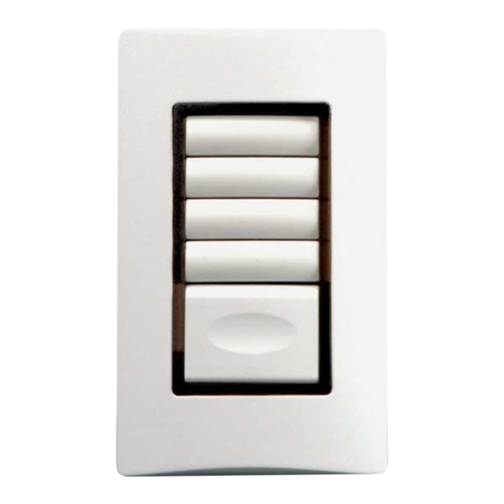
There are four basic Dataline Switch configurations: the single-gang, 1-,
2- and 4-button HDLS1SS-x, HDLS2SS-x and HDLS4SS-x, respectively,
and the two-gang, 8-button HDLS8SS-x.
Each switch includes bi-color LED status lights, as well as a locator light.
In addition, the 2-, 4- and 8-button units accept standard 3/8" wide (9 mm)
identification labels.
The -x suffix in the catalog number refers to button and switchplate color:
2 = ivory, 4 = almond, 7 = white and 9 = grey.
Any button on a Dataline Switch may be smartwired to:
• Any relay or group of relays within a single panel.
• A channel within a single panel, or the same channel throughout multiple
panels.
• A Complete Control group code.
See WinControl documentation for additional information.
These instructions cover wiring and testing of the Local Dataline and Dataline
Switches, manual smartwiring of the switches, and documenting the switch
and relay configuration.
If your installation is using the HCLK8SS Network Clock, HBMS8SS Building
Management System Interface Module, AA-Base Automation Appliance, or
Lighting Integrator Complete Control panels please refer to the documentation
provided with those products for additional programming information.
Before proceeding, read the instructions on the following pages. For an
overview of the entire system and the documentation forms, refer to the
other sections of the Lighting Integrator Installation and Operation Manual.
If you have any questions, call Technical Support at: 800.879.8585.
Datalines connect the relay panels, switches, and optional control modules. For simplicity, we refer to the 4-wire dataline running
between a panel and the dataline switches as a "Local Dataline." Within the 4-wire dataline are two twisted pairs: the red and black
wires (carrying data), and the blue and white wires (providing power to the dataline switches).
The panel provides low-voltage power to all of the dataline switches on its local dataline through the Automation Card terminals shown
below.
Refer to Lighting Integrator Interior Installation Instructions for more information about the Automation Card.
Local Dataline
RED
connections on
BLACK
Automation Card:
WHITE
Unshielded dual
BLUE
twisted pair (HDLW4)
LOCAL DATALINE
both pairs used
NOTE: To ensure good communication between panels, the installer must comply with the dataline specification.
Legrand/Wattstopper will not warrant a system using a dataline that does not meet our specifications.
To avoid questions, use HDLW4(P) (plenum rated). Do not run the dataline in conduit or wiring trays with power wires. Do not
connect the local datalines from two different panels.
DESCRIPTION
INSTALL THE LOCAL DATALINE
Wattstopper
Lighting Integrator Dataline Switch
Installation Instructions • Instructions d'Installation • Instrucciones de Instalación
HDLS1SS-x
®
HDLS4SS-x
HDLS2SS-x
HDLS8SS-x
Advertisement

Related Manuals for LEGRAND Wattstopper HDLS1SS


Summary of Contents for LEGRAND Wattstopper HDLS1SS
- Page 1 NOTE: To ensure good communication between panels, the installer must comply with the dataline specification. Legrand/Wattstopper will not warrant a system using a dataline that does not meet our specifications. To avoid questions, use HDLW4(P) (plenum rated). Do not run the dataline in conduit or wiring trays with power wires. Do not...
-
Page 2: Remove The Cover Plate
HDLW4P Dataline Wire Specifications REMOVE THE COVER PLATE • 18 AWG (7 strands x 26 AWG) To remove the screwless cover plate, press in the black tab at the bottom edge • 2 independent twisted pairs of the plate and lift the plate up and off as shown in Figure 1. To replace the •... - Page 3 Lighting Integrator Panel Lighting Integrator Panel (02) Second Floor (01) First Floor Automation Card Panels numbered (01) sequentially (02) Relays Automation Card Dual twisted pair (use both pairs of HDL W4P for local dataline) Dual twisted pair (use both pairs of HDL W4P for Dataline Switches local dataline)
- Page 4 Remove the wall plate and flip open the Master button open as shown… Figure 6 – Smartwiring a 1. Press the SMARTWIRE tab as shown in Figure 6. Dataline Switch The LED next to the tab will flash once, then the individual button LEDs will begin to flash ON/OFF. 2.
-
Page 5: Special Functions
Standard label makers can be used to make The screwless cover plate is Inserting the key into the key The individual switch buttons the 9mm directory labels. (Shown above easily removed by pressing slot and pressing the inner on the dataline switch unit and in the labeling examples on this page the black tab on the bottom of contact activates a keyed... - Page 6 All of the buttons are wired as Patterns. Reviewing the Figure 9 – Patterns Switch Operation switch button LED status shows why this is important (Figure 9). When the relay pattern for a switch button is “true”, the LED for that button will be on red. If “not true” the LED will be OFF.
- Page 7 ZONE 1 RELAY 01-01 CLEANING PATTERNS SWITCH SWITCH UNIT 01-01 CLEANING N NORTH CLEANING AREA CLEANING S BUTTON 1 – NORTH CLEANING ZONE 2 RELAY 01-02 BUTTON 2 – SOUTH CLEANING ZONE 3 RELAY 01-03 OCCUPANT OVERRIDE SWITCH SWITCH UNIT 01-02 SOUTH CLEANING AREA ZONE 4 BUTTON 1 –...
- Page 8 No. 24988 – 10/16 rev. 1 © Copyright 2016 Legrand All Rights Reserved. 800.879.8585 © Copyright 2016 Tous droits réservés Legrand. www.legrand.us/wattstopper © Copyright 2016 Legrand Todos los derechos reservados.