
Related Manuals for Juniper JOT Desk BL-3


Summary of Contents for Juniper JOT Desk BL-3
- Page 1 BL-3 JOT Desk Facing Workstation Includes Add-Ons: A1 | A2 | A3 | A4 | A5 General Installation Guide...
-
Page 3: Table Of Contents
Edition Code :: Facing Workstation ..............1 BL-3 :: Conference Table ..............11 BL-3 Add-ons :: Laminate Surface-Height End Panels......17 :: Laminate Divider-Height End Panels ......21 :: Steel Inset End Panels ............25... -
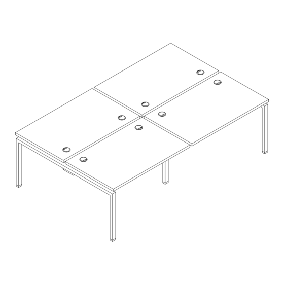
Page 4: Facing Workstation
Workstation Overview JOT Facing Workstation All parts listed are for a facing workstation; additional parts will be needed for additional facing workstations. - Page 5 Parts List Code Qty. Description GBXXXX Main Surface Long Beam Lock Plate BLPB2/ BLBB3 Cap Screw Locking Screw and Lever 60” End Leg BL60 Wood Screws 48” Intermediate Leg BL48INT Wood Screws 42” Support Bar* BASB72** Wood Screws Leg-Mount Cable Tray Hangers BCTLM** (Set of 2) CTXNL**...
- Page 6 1 | Assemble Intermediate Leg Align bracket with leg holes and bolt in place. Connect 4 brackets to leg. Insert 2 bolts per bracket to secure in place. 48" 60" 2 | Join End and Intermediate Leg Insert beam tabs into leg brackets. Guide beam tabs into bracket holes, ensuring that there is not a gap between the beam and legs.
- Page 7 3 | Join Second End Leg to Intermediate Leg Insert beam tabs into leg brackets. Guide beam tabs into bracket holes, ensuring that there is not a gap between the beam and legs. Using a rubber mallet, hammer beam to lock in place. 4 | Bolt Down Beam-to-Leg Lock Plate Note: Beam lock plates will not fit if there is a gap between beam and leg.
- Page 8 5 | Measure and Adjust Beam Width Measure from end leg to end leg until you find the approximate width of work surfaces. Insert screw through overlapping beam slots and into locking screw and lever. Slightly tighten screw. DO NOT fully tighten.
- Page 9 7 | Insert Beam Lock Adjust cable tray to approximate width of the work surface. Insert screw through overlapping beam slots and into the locking screw and lever. Slightly tighten the screw. DO NOT fully tighten. 8 | Leg Mount Cable Tray Bolt hanger to both ends of cable tray to mount on workstation.
- Page 10 9 | Surface Installation Measure from inner surface of leg bracket to outer edge of surface. Option 1: If installing dividers or monitor arms, leave 1 ” space between surfaces. • 24” deep surface, measure 21 ” • 30” deep surface, measure 23 ”...
- Page 11 10 | Secure First and Second Surface Place surface on top of frame and position according to the guidelines. Insert wood screws into leg brackets and secure to underside of the surface. 11 | Place Brackets on Facing Edge Clamp bracket to surface's side edge and tighten vertical bolt against surface to secure bracket.
- Page 12 12 | Secure Third Surface Place surface on top of frame and position according to guidelines. Insert wood screws into leg brackets and secure to underside of surface. 13 | Clamp Brackets to Side Edges Clamp bracket to surface's side edge and tighten vertical bolt against surface to secure bracket.
- Page 13 14 | Secure Fourth Surface and Tighten Beam Locks Place fourth surface on top of frame and position according to guidelines. Insert wood screws into leg brackets and secure to underside of surface. 15 | Secure Support Bars NOTE: Support bars will be added to surfaces 72” and longer. Place support bars as shown below and secure to underside of surface using wood screws.
-
Page 14: Conference Table
Conference Table Overview JOT Facing Workstation All parts listed are for a JOT conference table, additional parts will be needed for additional conference table. - Page 15 Parts List Code Qty. Description WAXXXX Main Surface Long Beam Lock Plate BLPB2/ BLBB3 Cap Screw Locking Screw and Lever 60” End Leg BL60 Wood Screws 48” Intermediate Leg BL48INT Wood Screws *Support bars will be added to surfaces 72” and longer. **Add-on items...
- Page 16 1 | Assemble Intermediate Leg Align bracket with leg holes and bolt in place. Connect 4 brackets to leg. Insert 2 bolts per bracket to secure in place. 48" 60" 2 | Join End and Intermediate Leg Insert beam tabs into leg brackets. Guide beam tabs into bracket holes, ensuring that there is not a gap between the beam and legs.
- Page 17 3 | Join Second End Leg to Intermediate Leg Insert beam tabs into leg brackets. Guide beam tabs into bracket holes, ensuring that there is not a gap between the beam and legs. Using a rubber mallet, hammer beam to lock in place. 4 | Bolt Down Beam-to-Leg Lock Plate Note: Beam lock plates will not fit if there is a gap between beam and leg.
- Page 18 5 | Measure and Adjust Beam Width Measure from end leg to end leg until you find the approximate width of work surfaces. Insert screw through overlapping beam slots and into locking screw and lever. Slightly tighten screw. DO NOT fully tighten.
- Page 19 7 | Tighten Beam Locks...
-
Page 20: A1: Laminate Surface-Height End Panels
A1: Laminate Surface-Height End Panels Overview JOT Facing Workstation All parts listed are for single side of workstation; additional parts will be needed for additional end panels.. - Page 21 Parts List Code Qty. Description GBEPLH62 or Laminate Surface-Height End Panel WABEPIS.D End Panel T-Bracket LEPBL1 Self-Tapping Screws Wood Screws...
- Page 22 1 | Secure Bracket to End Legs Attach 4 brackets to each end leg using self-tapping screws. Front of bracket will align flush with outside edge of leg. Align Flush...
- Page 23 2 | Attach End Panel Slide end panels into place and adjust until flush with bracket. Use wood screws to secure panel to each bracket.
-
Page 24: A2: Laminate Divider-Height End Panels
A2: Laminate Divider-Height End Panels Overview JOT Facing Workstation All parts listed are for a single panel; additional parts will be needed for additional panels. - Page 25 Parts List Code Qty. Description GBEPSS62 or Laminate Divider-Height End Panel WABEPDH.D End Panel T-Bracket LEPBL1 Self-Tapping Screws Wood Screws...
- Page 26 1 | Secure Bracket to End Legs Attach 4 brackets to each end leg using self-tapping screws. Front of bracket will align flush with outside edge of leg. Align Flush...
- Page 27 2 | Attach End Panel Slide end panels into place and adjust until flush with bracket. Use wood screws to secure panel to each bracket.
-
Page 28: A3: Steel Inset End Panels
A3: Steel Inset End Panels Overview JOT Facing Workstation All parts listed are for a steel inset end panel; additional parts will be needed for additional steel inset end panels. - Page 29 Parts List Code Qty. Description Steel Inset End Panel BEP60 or BCEP60 Self-Tapping Screws...
- Page 30 1 | Secure Panels to End Legs Slide the end panel into place and adjust until either flush with outside of leg or slightly recessed. Align Flush Slightly Recessed...
- Page 31 2 | Attach End Panel Use 4-6 self-tapping screws to secure panel to each leg.
- Page 32 1-866-999-0955 | hello@juniperoffice.com | juniperoffice.com © 2023 Juniper Office | Version 23.0.3...
Need help?
Do you have a question about the JOT Desk BL-3 and is the answer not in the manual?
Questions and answers