
Related Manuals for Juniper Flip-and-Fold OP


Summary of Contents for Juniper Flip-and-Fold OP
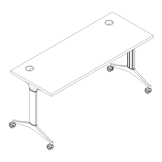
- Page 1 Flip-and-Fold Multipurpose Table Includes Add-Ons: A1 | A2 Watch Entire General Installation Guide Install Video...
- Page 3 Edition Code :: Flip-and-Fold ..................1 Add-ons :: Modesty Panel .................. 11 :: Power and Wire Management..........15...
- Page 4 Flip-and-Fold Overview Multipurpose Table All parts listed are for a single multipurpose table, additional parts will be needed for additional Watch Entire multipurpose tables. Install Video...
-
Page 5: Parts List
Parts List Qty. Description Code Main Frame Main Surface Leg Post OTF##V2 Leg Post Cap Foot Leg Top Cap Wire Clips... - Page 6 1 | Position Frame on Surface Turn surface upside down and place frame on surface. Measure and set frame location. Scan to Watch Step 30" Deep Surface 24" Deep Surface CENTERED CENTERED 1.5” 2 | Secure Frame to Surface Use (x8) wood screws to secure frame to underside of surface. Scan to Note: Assure frame stays squared.
- Page 7 3 | Measure to Position Release Handle Center handle on the surface and align flush with surface edge. Insert (x4) wood screws to secure handle. Scan to Watch Step 4 | Secure Wire Clips Assure wire is not sitting pass the surface edge. Secure wire clips with wood screws.
- Page 8 5 | Finish Securing Frame Pull handle to flip up frame base to access additional screw holes. Insert wood screws to secure frame. Scan to Watch Step 6 | (Optional) Prep Legs for Modesty Panel Note: If not installing a modesty panel, skip step and proceed to step 7. Scan to 6.1 Measure and Position Bolt in Legs Watch Step...
- Page 9 6.2 Secure Bolt to Legs Hold bolt in position. Slide washer on bolt and hand tighten nut. Lock bolt position by firmly tightening the nut with wrench. Scan to Watch Step 6.3 Secure Bolts to Frame On main frame, remove the plastic caps from both ends. Slide bolts down frame and use smaller side of measuring stick for bolt’s proper placement.
- Page 10 7 | Attach Post Legs to Frame Place cap onto end of post and into base. Insert socket cap screws and lock washers to secure legs to frame. Scan to Watch Step Note: Repeat process for both legs.
- Page 11 8 | Attach Feet to Post Legs Place cap onto end of post, and then set feet on top. Insert socket cap screws and anti-shake washers to secure feet to legs. Scan to Watch Step Note: Repeat process for both legs.
- Page 12 9 | Tighten Leg Bolts Confirm pre-installed leg bolts are tightened and flip table to upright position. Scan to Watch Step Note: When flipping table, be careful not to damage caster locks. 10 | Snap on Leg Top Caps When snapping on top caps, press the top part into place followed Scan to by bottom.
- Page 14 A1: Modesty Panel Overview Multipurpose Table All parts listed are for a single multipurpose table, additional parts will be needed for additional Watch Entire multipurpose tables. Install Video...
- Page 15 Parts List Qty. Description Code Steel Modesty Panel OMP## Modesty Panel Brackets (set of 2)
- Page 16 1 | Connect Brackets for Modesty Panel Fasten brackets to post legs and to main frame following hardware sequence below. Scan to Watch Step...
- Page 17 2 | Fasten Modesty Panel to Brackets Align inside of modesty panel screw holes with bracket’s screw holes. Insert (x4) screws and tighten. Scan to Watch Step...
- Page 18 A2: Optional Power Overview Multipurpose Table All parts listed are for a single multipurpose table, additional parts will be needed for additional Watch Entire multipurpose tables. Install Video...
- Page 19 Parts List Qty. Description Code PSMA Desktop Power Unit PSJ## Jumper PSPIF144 Infeed 114" Long OPCM Cable Clip System–Set of 18...
- Page 20 i | Perimeter Power System 1. Smart Box Power Infeed Has a standard NEMA 5-15P 15 amp plug on one end and a special connector on the opposite end. This device powers the system. 2. Desktop Power Unit Commonly known as a duplex outlet. Desktop power units come with a 3-port connector at the end of the cord that connects to the special connectors of...
- Page 21 1 | Mount Desktop Power Unit Open clamp so it is wider than the surface, place in desired location and hand tighten until snug. Scan to Watch Step 2 | Connect Jumpers to Link Power Units Pull handle and flip up surface. Insert the jumper connector into any 1 of power unit connector’s 3 ports.
- Page 22 3 | Attach Cable Clips Attach cable clips to frame and along side of legs to help with wire management. Scan to Watch Step 4 | Connect Power Infeed to Power Unit and Plug into Wall Outlet Scan to Insert power infeed’s special connector into any 1 of the power unit’s Watch Step 3 ports.
- Page 23 NOTES on Installing Perimeter Power System 1) Arrange tables as desired and place desktop power unit(s) on tables. 2) Connect jumpers between the user desktop units. Up to 8 2–power desktop units are allowed in the perimeter system. Desktop units with additional receptacles or USB chargers may reduce the number of allowed desktop units.
- Page 24 1-866-999-0955 | hello@juniperoffice.com | juniperoffice.com © 2023 Juniper Office | Version 23.1.2...
Need help?
Do you have a question about the Flip-and-Fold OP and is the answer not in the manual?
Questions and answers