Table of Contents
Advertisement
Quick Links
Advertisement
Table of Contents

Related Manuals for Deye BOS-G


Summary of Contents for Deye BOS-G
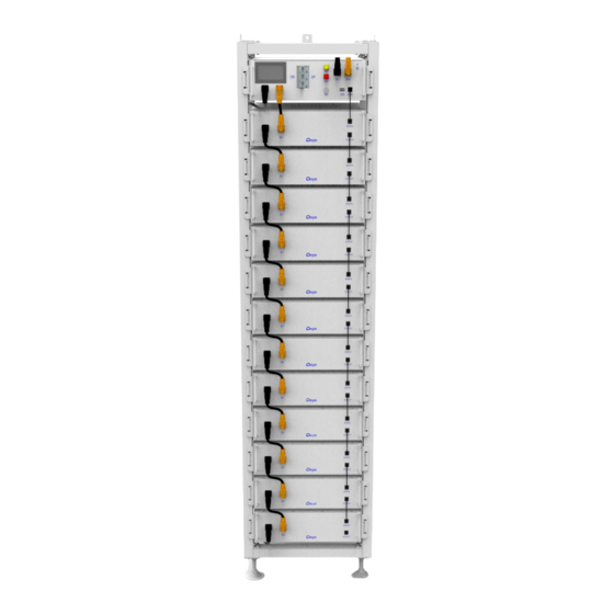
- Page 1 Installation and Operation Instructions LITHIUM STORAGE SYSTEM BOS-G Version:V1.3...
-
Page 3: Table Of Contents
6.2 Description of user interface .....................27 6.3 Fault viewing interface ...................... 28 6.4 Maintenance interface ...................... 29 7. BOS-G's fault description ......................30 8. Summary of fault types in BOS-G's screen and HVESS-Monitor ..........33 9. Maintenance and upgrade ......................35 9.1 Maintenance of BOS-G ......................35... - Page 4 9.2 USB's upgrade step ......................36 10. Battery module storage ......................36 11. Disposal ............................37 12. Appendix ............................. 38 12.1 Circuit diagram for on grid system with 12V supply ............38 12.2 System circuit diagram……………………………………………………….………………..…....39 13 Legal notice………………………………………………………………………………………………………….……………….40...
-
Page 5: Important Information In The Manual
The installation and operation manual applies to the modular battery energy storage system. Please carefully read this installation and operation manual to ensure the safe installation, preliminary debugging, and maintenance of BOS-G. Installation, preliminary debugging, and maintenance must be carried out by qualified and authorized personnel. Please keep this... -
Page 6: Meaning Of Symbols
1.3 Meaning of Symbols This manual contains the following types of warnings: Danger! It may cause an electric shock. Even when the equipment is disconnected from the power grid, the voltage-free state will have a time lag. Danger! If the instructions are not observed, death or severe injury may occur. - Page 7 • Store the battery module in a dry place within the temperature range specified in the data sheet. • Do not open, drill through or drop the battery cell or module. • Do not expose the battery cell or module to high temperatures. •...
-
Page 8: General Safety Information
Danger! Failure to comply with the safety information can lead to life-threatening situations. 1. Improper use can cause death. Operators of BOS-G must read this manual and observe all safety information. 2. Operators of BOS-G must comply with the specifications in this manual. -
Page 9: Proper Use
• The battery energy storage system can only be installed and operated in an enclosed space. The working environment temperature range of BOS-G is -20℃~ 55℃, and the maximum humidity is 85%. The battery module shall not be exposed to the sun or placed directly beside the heat source. -
Page 10: Requirements For Installation Personnel
1.8 Requirements for Installation Personnel All work shall comply with local applicable regulations and standards. The installation of BOS-G can only be completed by electricians with the following qualifications: • Trained in dealing with hazards and risks associated with the installation and operation of electrical equipment, systems, and batteries. -
Page 11: Safety Information
2.2 Safety information Part damage or short circuit may cause electric shock and death. A short circuit can be caused by connecting battery terminals, resulting in current flow. This type of short circuit shall be avoided under any circumstances. For this reason, follow these instructions: •... - Page 12 A tilting of the battery rack may cause injury. The maximum weight of a single battery rack of BOS-G can reach 628 kg. When tilted, they may overturn, causing injury and damage. Ensure that the battery cabinet is on a stable surface and that it does not tilt due to load or force.
-
Page 13: Permissible And Impermissible Storage Positions Of A Packaged Battery Module
The maximum weight of a single rack of BOS-G can reach 628 kg. We suggest that at least 2-3 people work together to install the battery rack. The lifting device is helpful for heavy parts, and the pulley or cart for light parts. -
Page 14: Preparation
4. Preparation 4.1 Tools required TOOL • Fix the upper and lower tripods to the side beam and the cross beam. • Install and connect the side beam/cross beam. • Fix the L-shaped bracket to the side beam. PHILIP2# crosshead screwdriver •... -
Page 15: Description And Installation Of Bos-G
2. When selecting the installation site, consider the transportation route and necessary site cleanup. 5.2 BOS-G Product Description BOS-G is a high-voltage lithium-ion battery system. It provides a reliable backup power supply for supermarkets, banks, schools, farms and small factories to smooth the load curve and achieve peak load transfer. It can also improve the stability of renewable systems and promote the application of renewable energy. -
Page 16: Product Data
5.3 Technical Data The energy of the battery system 61.44kWh (12 battery modules) Charge-discharge rate (Max) Battery cell chemistry LiFePO4 Maximum charging/discharging current 100A Module capacity 100Ah Working voltage 538~691V Working temperature Charge: 0~55℃/Discharge:-20~55℃ Humidity 5% - 85% (RH) The altitude of the installation site ≤... -
Page 17: Installation Of Rack
Description ① Side beam ② Crossbeam ③ Big tripod ④ Small tripod ⑤ L-bracket assembly ⑥ Diagonal brace ⑦ Bottom plate parts ⑧ Base ⑨ Rack fastener ⑩ M4*12 outer hexagon cross combination screw ⑪ M6*12 outer hexagon cross combination screw ⑫... -
Page 18: Update Description Of Rack
5.5 Update description of Rack 5.5.1 3U-HRack 2G Parts description Description ① Side beam ② Top beam ③ Bottom beam ④ Left diagonal brace ⑤ Right diagonal brace ⑥ Round head hexagon socket combination screws ⑦ Hexagonal wrench ⑧ Base ⑨... -
Page 19: Update Installation Of Rack
5.5.2 Update Installation of Rack ① Take out two side beams and top and bottom beams and assemble them into a rectangular frame, connect the two top beams with the side beams, and then fix the side beams and top beams with the round head hexagon combination screws and hexagonal wrench. -
Page 22: Description Of Battery Module
5.6 Description of Battery Module Name Description ① Battery module negative pole (black) ② BCOM OUT Connection position of battery module communication and power supply output ③ Battery module positive pole (orange) ④ BCOM IN Connection position of battery module communication and power supply input 5.7 Description of High-Voltage Control Box Name... -
Page 23: Description Of Battery Module In Rack
light ⑧ High-voltage hazard indicator (yellow) Front indicator ALRM light ⑨ Battery system fault alarm indicator (red) Front indicator ⑩ PCS- Connection position of PCS negative pole (black) Front ⑪ PCS+ Connection position of PCS positive pole (orange) Front Grounding wire ⑫... - Page 24 Description quantity ① High-voltage control box 750V/100A ② 5.12kWh battery module (general) ③ 120ohm terminal resistor ④ Communication cable (110 mm for battery module, 140 mm for Standard high-voltage control box) ⑤ 220 mm positive power cord of high-voltage control box Standard ⑥...
-
Page 25: Installation Of The Battery Module To The Rack
Definition high-voltage control box interface Definition of the battery module interface Definition BMS-BMU Definition communication upper Definition interface interface lower BMU interface BMU_CANL BMU_CANL BMU_CANL BMU_CANH BMU_CANH BMU_CANH 5.9 Installation of the Battery Module to the Rack Insufficient or no grounding may cause an electric shock. Device malfunctions, and insufficient or no grounding may cause device damage and life-threatening electric shocks. -
Page 26: Startup Steps Of Pack
④ After the battery module is placed in the control box, take out a 140 mm communication cable to connect the communication port of the battery module and the high-voltage control box, and 11x110mm communication cables to connect the battery module communication port (IN-OUT) from top to bottom. - Page 27 ③ Click the icon on screen to enter the maintenance system password confirmation interface. ④ Enter the password 123 and press the Confirm key to enter the main interface of system maintenance. The operation shall be performed by a professional. ⑤...
-
Page 28: External 12V Power Supply Of High-Voltage Control Box
5.11 External 12V Power Supply of High-Voltage Control Box To operate the high-voltage control box with an external 12V power supply, please contact our service personnel. Hotline: +86 0574 8612 0560, Email: service-ess@deye.com.cn. In the factory configuration, the high-voltage control box is supplied with working voltage from an internal power supply unit. -
Page 29: Description Of User Interface
6.2 Description of User Interface (1) Basic Parameters No Wi-Fi icon on the screen indicates no Wi-Fi signal. • The flashing Wi-Fi icon on the screen indicates the • Wi-Fi is in connecting. Wi-Fi Icon The Wi-Fi icon on the screen indicates the Wi-Fi is •... -
Page 30: Fault Viewing Interface
Fault viewing interface Click the icon on screen to enter the maintenance system password confirmation interface. Enter the password 123 and press the Confirm key. The enter main interface of system. The operation shall be performed by a professional. -
Page 31: Maintenance Interface
For safety, please unplug the power cord of the positive and negative interfaces before maintenance. Note: When inserting the SD card, unplug the battery power cord and manually turn the air switch to the off position. 7. BOS-G’ fault description Different types of faults are below: Fault types Trigger conditions... - Page 32 Charge overtemperature Exceeding the parameter set value and set time alarm (>45℃, 2s) Charge overtemperature Exceeding the parameter set value and set time protection (>50℃, 2s) Discharge Exceeding the parameter set value and set time overtemperature alarm (>50℃, 2s) Discharge Exceeding the parameter set value and set time overtemperature (>55℃, 2s)
- Page 33 overtemperature alarm connector overtemperature Exceeding the parameter set value and set time protection connector Exceeding the parameter set value and set time overtemperature alarm connector overtemperature Exceeding the parameter set value and set time System faults protection Power loop Exceeding the parameter set value and set time overtemperature alarm Power loop...
- Page 34 BMU lost BMU message not received for a long time Abnormal number of BMU The number of BMU addresses is different from the number of set parameters Note: more information, please contact Email: service-ess@deye.com.cn, Service Hotline: +86 0574 8612 0560.
-
Page 35: Summary Of Fault Types In Bos-G's Screen And Hvess-Monitor
8. Summary of fault types in BOS-G’S screen and HVESS-Monitor Screen protection event HVESS-Monitor protection event HVESS-Monitor alarm event Abbreviation description description description BMS southward connector connector overtemperature connector overtemperature protection overtemperature alarm BMS northward connector connector overtemperature connector overtemperature... - Page 36 Cell undervoltage level-2 Cell undervoltage protection Cell undervoltage alarm alarm Abnormal numbers of BMU Abnormal numbers of BMU BMU lost BMU lost RTC clock fault RTC clock fault Current module fault Current module fault SCHG total voltage SCHG total voltage acquisition fault acquisition fault Abnormal RS485...
-
Page 37: Maintenance And Upgrade
Before maintenance, ensure that BOS-G is decommissioned according to relevant provisions. Note: All maintenance work shall comply with local applicable regulations and standards. The USB disk port of BOS-G has the functions of upgrading firmware and recording battery data, which can be used as an auxiliary tool. -
Page 38: Usb's Upgrade Step
Note: If the system is installed in a polluted environment, maintenance and cleaning must be carried out at short intervals. Note: Clean the battery rack with a dry-cleaning cloth. Ensure that no moisture comes into contact with the battery connections. Do not use solvents. 9.2 USB’s Upgrade Step ①... -
Page 39: Disposal
11. Disposal For details related to the disposal of battery modules, please contact us. Service Hotline: +86 0574 8612 0560, Email: service-ess@deye.com.cn. For more information, please visit http://deyeess.com. Observe applicable regulations on waste battery disposal. Immediately stop the use of damaged batteries. -
Page 40: Appendix
12. Appendix 12.1 Circuit diagram for on grid system with 12V supply... -
Page 41: System Circuit Diagram
12.2 System Circuit diagram... -
Page 42: Legal Notice
Legal Statement The information contained in the document is the property of Deye ESS Technology Co., Ltd. D All information shall not be published in whole or in part without the written permission of Deye ESS Technology Co., Ltd.
Need help?
Do you have a question about the BOS-G and is the answer not in the manual?
Questions and answers