Advertisement
INSTALLATION REQUIREMENTS
Tools and Parts
Gather the required tools and parts before starting installation. Read and follow the instructions provided with any tools listed here.
Tools needed

Parts supplied
Remove parts from package. Check that all parts are included.

Parts needed

Optional accessories

*For information on ordering, see the "Assistance or Service" section.
Location Requirements

Observe all governing codes and ordinances.
- It is the installer's responsibility to comply with installation clearances specified on the model/serial/rating plate. The model/serial/rating plate is located inside the range hood on the left wall.
- Range hood location should be away from strong draft areas, such as windows, doors and strong heating vents.
- Cabinet opening dimensions that are shown must be used. Given dimensions provide minimum clearance. Consult the cooktop/range manufacturer installation instructions before making any cutouts.
- This range hood is recommended for use with cooktops with a maximum total rating of 40,000 BTUs or less.
- Grounded electrical outlet is required. See "Electrical Requirements" section.
- All openings in ceiling and wall where range hood will be installed must be sealed.
- These range hoods are factory set for non-vented installations and require charcoal filters. See the "Assistance or Service" section for information on ordering charcoal filters.
For Mobile Home Installations
The installation of this range hood must conform to the Manufactured Home Construction Safety Standards, Title 24 CFR, Part 328 (formerly the Federal Standard for Mobile Home Construction and Safety, title 24, HUD, Part 280) or when such standard is not applicable, the standard for Manufactured Home Installation 1982 (Manufactured Home Sites, Communities and Setups) ANSI A225.1/NFPA 501A, or latest edition, or with local codes.
Product Dimensions

Installation Clearances

- 24" (61 cm) minimum distance from electric cooking surface 24" (61 cm) minimum distance from gas cooking surface 30" (76.2 cm) suggested maximum above the cooking surface
- 18" (45.7 cm) minimum clearance - upper cabinet to countertop
- 30" (76.2 cm) minimum cabinet opening width for 30" (76.2 cm) models and 36" (91.4 cm) minimum cabinet width for 36" (91.4 cm) models
- 12" (30.5 cm) cabinet depth
- 36" (91.4 cm) base cabinet height
Venting Requirements
These range hoods are factory set for non-vented (recirculating) installations and come with a charcoal filter. See the "Assistance or Service" section for information on ordering a charcoal filter kit, Part Number W10355450.
Electrical Requirements
Observe all governing codes and ordinances.
Ensure that the electrical installation is adequate and in conformance with National Electrical Code, ANSI/NFPA 70 (latest edition) or CSA Standards C22.1-94, Canadian Electrical Code, Part 1 and C22.2 No. 0-M91 (latest edition), and all local codes and ordinances.
If codes permit and a separate ground wire is used, it is recommended that a qualified electrician determine that the ground path is adequate. A copy of the above code standards can be obtained from:
National Fire Protection Association
1 Batterymarch Park
Quincy, MA 02169-7471
CSA International
8501 East Pleasant Valley Road Cleveland, OH 44131-5575
- A 120 V, 60 Hz, AC only, 15 A, fused electrical circuit is required.
- If the house has aluminum wiring, follow the procedure below:
Connect the aluminum wiring using special connectors and/or tools designed and UL listed for joining copper to aluminum.
Follow the electrical connector manufacturer's recommended procedure. Aluminum/copper connection must conform with local codes and industry accepted wiring practices. - Wire sizes and connections must conform with the rating of the appliance as specified on the model/serial/rating plate. The model/serial/rating plate is located inside the range hood on the left wall.
- Wire sizes must conform to the requirements of the National Electrical Code, ANSI/NFPA 70 (latest edition) or CSA Standards C22. 1-94, Canadian Electrical Code, Part 1 and C22.2 No. 0-M91 (latest edition), and all local codes and ordinances.
INSTALLATION INSTRUCTIONS
- Disconnect power
![]()
Electrical Shock Hazard
Disconnect power before servicing.
Replace all parts and panels before operating.
Failure to do so can result in death or electrical shock. - Mark hole locations

Align the exterior edge of the mounting brackets with the exterior edges of the upper cabinet.
![]()
The brackets should touch the upper cabinet. With a pencil, mark the upper holes on the brackets. - Install brackets

- Using a #2 Phillips screwdriver, install the drywall anchors.
- Using #8-18 x 1" (4.2 x 25 mm) flat-head #2 Phillips screws, install the mounting brackets using the upper holes.
NOTE: For installations to a surface other than drywall, it is recommended that a qualified contractor determine the anchoring method.
- Prepare Range Hood

- Set the range hood on its back on a covered surface.
- Using a #2 Phillips screwdriver, remove the electrical box cover.
- Using a flat-blade screwdriver, remove the appropriate power supply knockout.
- Mark hole locations

Lift the range hood into place and insert the mounting bracket tabs through the slots in the back of the range hood.

Hold the range hood firmly in place with one hand and bend each mounting tab (A) upward approximately 90°. Mark the hole at the power supply knockout (B).
OPTIONAL: Mark the hole in each mounting tab. Remove the range hood and set it aside. - Drill electrical opening

Using a 1 / 1 4 " (3 cm) drill bit, drill the hole in the dot marked previously at the electrical strain relief.
OPTIONAL: Using a 1/8" (3 mm) drill bit, drill pilot holes for the dots marked previously at each mounting tab at an approximate 45° angle in an upward direction. - Prepare range hood vents and mounting tabs

- Install Strain Relief
Install a UL listed/CSA approved 1/2" (13 mm) strain relief (A). - Mounting Tabs
Start a #8-18 x 5/8" (4.2 x 16 mm) truss-head screw into the mounting tab (D) on each side of the range hood as shown in the inset. Insert the screws approximately 2 turns into the mounting tab holes. - Non-vent (Recirculating) Installations
Remove the (2) T10 Torx ®† screws and remove the top, front rectangular vent cover (B).
- Install Strain Relief
- Mount Range Hood

- Lift the range hood into place, positioning the rear slots over the mounting brackets.
- Using a Phillips screwdriver, push on the screws that are started into the top mounting tabs and bend the tabs against the cabinet side walls. Attach the screws to the cabinet side walls.
![]()
Do not overtighten the screws. - For direct wire installations, run the home power supply cable according to the National Electric Code or CSA standards and local codes and ordinances. There must be enough wiring from the fused disconnect (or circuit breaker) box to make the connection in the range hood electrical terminal box.
- Tighten the strain relief screws.
NOTE: Do not reconnect power until the installation is complete.
OPTIONAL: If you prefer, bend the rear tabs against the rear of the range hood and attach to the wall using #8-18 x 5/8" (4.2 x 16 mm) truss-head screws.
- Make electrical connection
![]()
Option 1 - Direct Wire Installations- Use a UL listed/CSA approved wire connector and connect the 3 white wires (A) together.
- Use a UL listed/CSA approved wire connector and connect the 2 black wires (B) together.
![]()
Fire Hazard
Electrically ground the blower.
Use copper wire.
Connect ground wire to green ground screw in terminal box.
Failure to do so can result in death, fire, or electrical shock. - Connect the green (or bare) ground wire (C) from the power supply to the green ground screw in the electrical box and tighten the screw securely.
Reinstall the electrical box cover.
Reconnect power.
Option 2 - Power Cord Kit Installations
For optional power cord kit installations, follow the instructions supplied with the power cord kit. See the "Assistance or Service" section for information on ordering.
NOTE: Use only with range hood cord connection kits that have been investigated and found acceptable for use with this model range hood. - Complete the installation
- Install a 120 V, 75 W maximum, light bulb with E26 base. See "Replacing the Light Bulb" in the "Range Hood Care" section.
- If removed previously, replace the filter. See "Charcoal Grease Filter" in the "Range Hood Care" section.
- Check the operation of the range hood fan and light. See the "Range Hood Use" section.
If the range hood does not operate, check to see whether a circuit breaker has tripped or a household fuse has blown.
Disconnect the power and check the wiring connections.


NOTE: To get the most efficient use from your new range hood, read the "Range Hood Use" section.
RANGE HOOD USE
The range hood is designed to remove smoke, cooking vapors, and odors from the cooktop area. For best results, start the hood before cooking and allow it to operate several minutes after the cooking is complete to clear all smoke and odors from the kitchen.
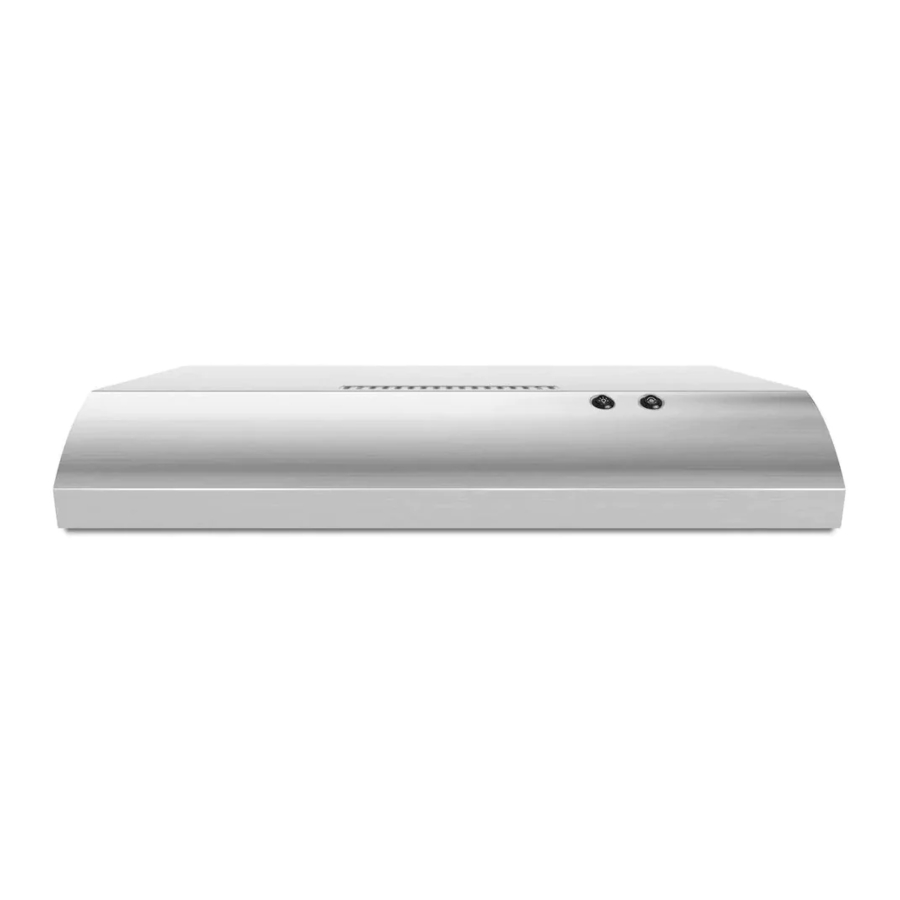
The hood controls are located on the front panel of the range hood.

- Light housing and cover
- Grease filter retainer
- Grease filter
Range Hood Controls

- On/Off light switch
- Fan speed switch
Operating the light
Press the light switch to the left to turn the light On.
Press the light switch to the right to turn the light Off.
Flicker and visual fluctuation can be present every time the lamp switch is activated. The duration of the flicker will depend on the manner and velocity that the light switch changes position.
Operating the fan
The fan has 2 speeds.
Press the fan switch to the left for Low speed.
Press the fan switch to the right for High speed.
Return the fan switch to the center to turn the fan Off.
RANGE HOOD CARE
Cleaning
Clean the hood and grease filters frequently according to the following instructions. Replace the grease filter before operating hood.
Exterior Surfaces
Do not use soap-filled scouring pads, abrasive cleaners, cooktop polishing creme, steel wool, gritty washcloths, or paper towels.
To avoid damage to the stainless steel, do not use cleaners that contain chlorine.
Cleaning Method:
- Liquid detergent or all-purpose cleaner:
- Rinse with clean water and dry with a soft, lint-free cloth.
- Glass cleaner to remove fingerprints.
- For stainless steel models, rub in the direction of the grain to avoid scratching or damaging the surface. See the "Assistance or Service" section to order.
Charcoal Grease Filter
To Remove the Filter:
- Remove the screw from the grease filter retainer.
- Turn the grease filter retainer to release the filter.

- Filter retainer
- For non-vented (recirculating) installations: The charcoal filter is not washable. It should last up to 6 months with normal use. For information on ordering, see the "Assistance or Service" section. Dispose of the old charcoal filter.

To Replace the Filter:
- To reinstall the filter, place the back edge of the filter into the channel at the rear of the hood. Push the filter into place and turn the filter retainer to secure the filter to the range hood.
- Replace the screw in the grease filter retainer.
Replacing the Light Bulb
Turn off the range hood and allow the light bulb to cool.
- Disconnect power.
- Squeeze the plastic lens cover and remove it from the hood.

- Screw a 120 V, 75 W maximum, light bulb with E26 base into the socket.
- Replace the lens cover by squeezing the cover and inserting the tabs into the slots.
- Reconnect power.
If the new light does not operate, make sure the light bulb is inserted correctly before calling service.

WIRING DIAGRAM

ASSISTANCE OR SERVICE
If you need service
Please refer to the warranty.
If you need replacement parts
If you need to order replacement parts, we recommend that you use only factory specified parts. Factory specified parts will fit right and work right because they are made with the same precision used to build every new appliance.
To locate factory specified replacement parts in your area, call the following customer assistance telephone number or your nearest designated service center.
In the U.S.A.
Call the Whirlpool Customer eXperience Center toll-free: 1-800-253-1301 or visit our website at www.whirlpool.com.
Our consultants provide assistance with:
- Scheduling of service. Whirlpool designated service technicians are trained to fulfill the product warranty and provide after-warranty service anywhere in the United States.
- Features and specifications on our full line of appliances.
- Referrals to local dealers.
- Installation information.
- Use and maintenance procedures.
- Accessory and repair parts sales.
- Specialized customer assistance (Spanish speaking, hearing impaired, limited vision, etc.).
For further assistance
If you need further assistance, you can write to Whirlpool Corporation with any questions or concerns at:
Whirlpool Brand Home Appliances
Customer eXperience Center
553 Benson Road
Benton Harbor, MI 49022-2692
Please include a daytime phone number in your correspondence.
In Canada
Call the Whirlpool Canada LP Customer eXperience
Centre toll-free: 1-800-807-6777 or visit our webpage www.whirlpool.ca.
Our consultants provide assistance with:
- Scheduling of service. Whirlpool designated service technicians are trained to fulfill the product warranty and provide after-warranty service anywhere in Canada.
- Features and specifications on our full line of appliances.
- Referrals to local Whirlpool dealers.
- Use and maintenance procedures.
- Accessory and repair parts sales.
- Referrals to local dealers, repair parts distributors, and service companies. Whirlpool Canada LP designated service technicians are trained to fulfill the product warranty and provide after-warranty service anywhere in Canada.
For further assistance
If you need further assistance, you can write to Whirlpool Canada LP with any questions or concerns at:
Whirlpool Brand Home Appliances
Customer eXperience Centre Whirlpool Canada LP
200 - 6750 Century Ave.
Mississauga, Ontario L5N 0B7
Please include a daytime phone number in your correspondence.
RANGE HOOD SAFETY
Your safety and the safety of others are very important.
We have provided many important safety messages in this manual and on your appliance. Always read and obey all safety messages.
This is the safety alert symbol.
This symbol alerts you to potential hazards that can kill or hurt you and others.
All safety messages will follow the safety alert symbol and either the word "DANGER" or "WARNING." These words mean:

You can be killed or seriously injured if you don't immediately follow instructions.

You can be killed or seriously injured if you don't follow WARNING instructions.
All safety messages will tell you what the potential hazard is, tell you how to reduce the chance of injury, and tell you what can happen if the instructions are not followed.


Documents / Resources
References
![www.whirlpool.com]() Home, Kitchen & Laundry Appliances & Products | Whirlpool
Home, Kitchen & Laundry Appliances & Products | Whirlpool![www.whirlpool.ca]() Shop Kitchen Appliances: Washing Machines, Dryers & More | Whirlpool
Shop Kitchen Appliances: Washing Machines, Dryers & More | Whirlpool
Download manual
Here you can download full pdf version of manual, it may contain additional safety instructions, warranty information, FCC rules, etc.
Download Whirlpool UXT4030AD, UXT4036AD - 30" Range Hood with the FIT System Manual
Advertisement


Need help?
Do you have a question about the UXT4030AD and is the answer not in the manual?
Questions and answers