Table of Contents
Advertisement
Quick Links
Advertisement
Table of Contents

Subscribe to Our Youtube Channel
Related Manuals for Lincoln industrial Quicklub 203


Summary of Contents for Lincoln industrial Quicklub 203
- Page 1 Owner Manual Technical Description 2.1A-30002-B00 Quicklub ® Pump model 203 with power supply board for 94 - 265 VAC with and without printed circuit board V 10 - V 13 10011327 LINCOLN GmbH • Postfach 1263 • D-69183 Walldorf • Tel +49 (6227) 33-0 • Fax +49 (6227) 33-259...
-
Page 2: Fields Of Applications Of Quicklub Progressive Central Lubrication Pumps
Owner Manual Technical Description 2.1A-30002-B00 Fields of Applications of the QUICKLUB Progressive Central Lubrication Pumps Industry - Maschines Pump Type Pump Reservoir Low-level control for all reservoir sizes available on request Control: See the respective model designation on the pump nameplate e.g. P203 - 2XN - 1K6 - 24 - 1A1.10 - V10 Page 2 of 32 LINCOLN GmbH •... -
Page 3: Table Of Contents
Control p. c. b. V10-V 13 ..........14 Safety instructions ............4 Pump types ..............5 Identification Code - Pump Models 203 ...... 6 Description of the QUICKLUB 203 Central Lubrication Pump ........... 7 Mode of operation ............8 Maintenance, repair and tests ........19 Troubleshooting ............ -
Page 4: Safety Instructions
Owner Manual Technical Description 2.1A-30002-B00 Safety instructions Appropriate Use Installation General Safety Instructions Regulations for Prevention of Accidents Operation, Maintenance and Repair Attention: In the case of pumps which are filled from the reservoir cover, switch off the power supply before filling in the lubricant. Attention: means of pumps with a large delivery volume... -
Page 5: Pump Types
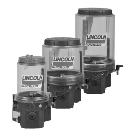
Owner Manual Technical Description 2.1A-30002-B00 Pump Types 1173a95 Fig. 1: - Variants of pump model 203 The 203 pumps • Control unit models 203 • Reservoir sizes: Electric connection industrial applications * Refer to the designation on the pump nameplate. Example: P203 - 4XNBO - 1 K6 - AC - 1A1.01 - V10 Also refer to the designation code on page 6. -
Page 6: Identification Code - Pump Models 203
Owner Manual Technical Description 2.1A-30002-B00 Identification Code - Pump Models 203 Examples of model designation P203- 2 K6 - 01 - V10 P203- 4 K7 - Basic pump model for grease or oil with 1-3 outlets and 24 VDC motor Reservoir design 2 - 2 l Transparent plastic reservior 4 - 4 l transparent plastic reservior... -
Page 7: Description Of The Quicklub 203 Central Lubrication Pump
Owner Manual Technical Description 2.1A-30002-B00 Description of the QUICKLUB 203 Central Lubrication Pump • The QUICKLUB 203 central lubrication pump 00002618b Fig. 2 - Pump components 1 - Reservoir 5 - Plug 2A1 2 - Pump element 6 - Filling nipple, pump... -
Page 8: Mode Of Operation
Owner Manual Technical Description 2.1A-30002-B00 Mode of Operation Pump Elements with fixed Lubricant output 20002068 Fig. 4 - Pump element Note: Pump elements with piston diameter C 7 must be used for supplying of chisel paste. The design and the mode of 1 - Piston 2 - Return spring operation are the same as those of the pump elements with... - Page 9 Owner Manual Technical Description 2.1A-30002-B00 Check valve 1 - Reservoir with stirring paddle 2 - Pump 3 - Check valve, spring-loaded 4 - Pressure limiting valve R - Return line P - Pressure line 1164b95 Fig. 7 - Hydraulic diagram of the pump Arrangement of the pump elements 1163a95 Fig.
- Page 10 Owner Manual Technical Description 2.1A-30002-B00 4159a98 Fig. 10 - Sectional view: adjustable element 1 - adjusting spindle SW 16 3 - pump element body 6 - control piston (with over flats) 4 - gasket 7 - delivery piston 2 - counternut SW 24 5 - pump cylinder S - dimension Setting of adjustable pump elements...
- Page 11 Owner Manual Technical Description 2.1A-30002-B00 Pressure Relief Valve Pressure relief valve without grease return Important! Note: The pumps model 203 are equipped without pressure relief valve. When ordering the pumpe, order the pressure reli- ef valve seperately. See the Parts Catalog under Pressure reli- 10022618a Fig.
-
Page 12: Low-Level Control (Optional)
Owner Manual Technical Description 2.1A-30002-B00 Return Line Connection 10032618 Fig. 15 - Return line connection Low-Level Control (optional) Pump for Grease When the reservoir is filled • clockwise • cannot • When the reservoir is empty • 00002444 Fig. 16 - Switching parts of the low-level control 1 - Guiding plate with round solenoid 2 - Electromagnetic switch (at stirring paddle) 3 - Control cam... - Page 13 Owner Manual Technical Description 2.1A-30002-B00 4237a99 Fig. 17- Connecting diagram, pump for grease, magnetic floating switch Pump for Oil Magnetic floating switch • Note: The life of the magnetic circuit breaker strongly depends on the conditions under which it is loaded. Since the data rela- tive to the maximum switching capacity refer to strictly resistive loads, which cannot be always guaranteed in practice, it is ne- cessary to take the corresponding contact protection measures...
-
Page 14: Control P. C. B. V10-V 13
Owner Manual Technical Description 2.1A-30002-B00 Control p. c. b. V10 - V13 * Mode of Operation The printed circuit board 1 - printed circuit board 2 - power supply board 4238a99 Fig. 20 - Printed circuit board in the pump housing. 20002443b Fig. - Page 15 Owner Manual Technical Description 2.1A-30002-B00 The pause time The operating time Time storage 20002438 20002438 Page 15 of 32 LINCOLN GmbH • Postfach 1263 • D-69183 Walldorf • Tel +49 (6227) 33-0 • Fax +49 (6227) 33-259...
- Page 16 Owner Manual Technical Description 2.1A-30002-B00 Time Setting Note :To reset a jumper (see fig 25 or 27), remove the printed circuit board . Important: 00002617 Figure 23- The cover to access hte printed circuit board has been removed To set the pause time blue rotary switch Time ranges: Minutes or hours 20002451b...
- Page 17 Owner Manual Technical Description 2.1A-30002-B00 To set the operating time Time Ranges : Seconds or minutes 20002453b Fig.26- Rotary switch -operating time Switch Position Note: When the switch is on ‘’0“ a fault is shown at the right- hand LED 3 Fig. 28. At the same time the factory-set operating time is accepted.
- Page 18 Owner Manual Technical Description 2.1A-30002-B00 Repair If the printed circuit board must be replaced , a model V 10 Operational Test / To Trigger an additional lubrication cycle (> 2 seconds) 20002457b Fig. 28 - LED on the printed circuit board 1 - LED, left hand 4 - Rotary switch, operating time 2 - Rotary switch, pause time...
-
Page 19: Maintenance, Repair And Tests
Owner Manual Technical Description 2.1A-30002-B00 Maintenance, Repair and Tests Maintenance Note: Whenever work is done on the centralized lubrication sy- stem, particular attention should be paid to absolute cleanli- ness. Dirt in the system will cause problems. • Pump Filling 2 l - reservoirs 4 l , 8 l - reservoirs Important! - Page 20 Owner Manual Technical Description 2.1A-30002-B00 Replace the pump element Important: Note: Pump element with adjustable lubricant output is set to the same output as the old pump element Fig. 30 - Replacing the pump elememt Tests Operational Test / Triggering an Additional Lubrication Cycle To Check the Pressure relief valve 1st option...
-
Page 21: Troubleshooting
Owner Manual Technical Description 2.1A-30002-B00 Troubleshooting the case of pumps with integrated control units, please refer to Note: The pump operation can be checked from the outside by the paragraph of the printed circuit board. observing whether the stirring paddle is rotating (e.g. by trigge- ring an additional lubrication). -
Page 22: Technical Data
Owner Manual Technical Description 2.1A-30002-B00 Technical Data Pump Electrical connection: Internal fuse *Note: The pump is designed for the above mentioned tempe- rature range. The lubricants used must still be pumpable at the temperatures mentioned above. In case of doubt, consult the Motor: lubricant manufacturer. - Page 23 Owner Manual Technical Description 2.1A-30002-B00 Time settings for pumps with p. c. b. Pump element with fixed lubricant output Important! Torsion torques Pump element with adjustable lubricant output Weights Safety valve individual weights”: 2 l reservoir, standard design 4 l reservoir, standard design * Note: The 4l and 8l reservoirs have the standard design ”fil- ling from top”.
- Page 24 Diagram of connections - Pump without p. c. b. 4235b99 Fig. 32 - Diagram of connections of QUICKLUB 203 without p. c. b. Connection by means of a square type plug, DIN 43650-A Note: For the connection of the low level control also see the diagrams of connections and contact protection measures on page 13.
- Page 25 Diagram of connections - Pump with V 10 - V 13 p. c. b. 4236b99 Fig. 33 - Diagram of connections of QUICKLUB 203 with p. c. b. Connection by means of a square type plug, DIN 43650-A Note: For the connection of the low level control also see the diagrams of connections and contact protection measures on page 13.
- Page 26 Owner Manual Technical Description 2.1A-30002-B00 Dimensions 2 l Reservoir 1166a95 Page 26 of 32 LINCOLN GmbH • Postfach 1263 • D-69183 Walldorf • Tel +49 (6227) 33-0 • Fax +49 (6227) 33-259...
- Page 27 Owner Manual Technical Description 2.1A-30002-B00 2 l Reservoir with Filling from Top 1167a95 Page 27 of 32 LINCOLN GmbH • Postfach 1263 • D-69183 Walldorf • Tel +49 (6227) 33-0 • Fax +49 (6227) 33-259...
- Page 28 Owner Manual Technical Description 2.1A-30002-B00 2 l Flat-Type Reservoir 1168a95 Page 28 of 32 LINCOLN GmbH • Postfach 1263 • D-69183 Walldorf • Tel +49 (6227) 33-0 • Fax +49 (6227) 33-259...
- Page 29 Owner Manual Technical Description 2.1A-30002-B00 4 l Reservoir 1169a95 Page 29 of 32 LINCOLN GmbH • Postfach 1263 • D-69183 Walldorf • Tel +49 (6227) 33-0 • Fax +49 (6227) 33-259...
- Page 30 Owner Manual Technical Description 2.1A-30002-B00 8 l Reservoir 1170a95 Page 30 of 32 LINCOLN GmbH • Postfach 1263 • D-69183 Walldorf • Tel +49 (6227) 33-0 • Fax +49 (6227) 33-259...
- Page 31 Owner Manual Technical Description 2.1A-30002-B00 Attaching Boreholes of the 2l, 4l, 8l, Pump 1171a95 Note: Thighten pump models wih 2 l - flat, 4 L - and 8 L reservoir with three fastening screws (see pt .9,5) Page 31 of 32 LINCOLN GmbH •...
-
Page 32: Lubricants
Owner Manual Technical Description 2.1A-30002-B00 Lubricants Important : Lubricating greases for QUICKLUB systems Manufacturer Designation Base soap min. delivery temerature Bio-degradable greases Manufacturer Designation Base soap min. delivery temperature Use Lubricants with solid matter additives only after having consulted the manufacture system. Page 32 of 32 LINCOLN GmbH •...
Need help?
Do you have a question about the Quicklub 203 and is the answer not in the manual?
Questions and answers