
Subscribe to Our Youtube Channel
Related Manuals for Lincoln industrial QUICKLUB 203


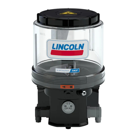
Summary of Contents for Lincoln industrial QUICKLUB 203
- Page 1 Owner Manual Technical Description 2.1A-30001-D00 QUICKLUB ® Pump Model 203 Without Control Unit 10071327 Page 1 from 28 LINCOLN GmbH • Postfach 1263 • D-69183 Walldorf • Tel +49 (6227) 33-0 • Fax +49 (6227) 33-259...
-
Page 2: Fields Of Applications Of Quicklub Progressive Central Lubrication Pumps
Owner Manual Technical Description 2.1A-30001-D00 Fields of Applications of the QUICKLUB Progressive Central Lubrication Pumps Industry - Machines - Commercial Vehicles - Pump Type Building Machinery - Agricultural Machines Pump Reservoir Low-level control (option)for all reservoir sizes available , on request Control: Control Control... -
Page 3: Table Of Contents
Safety instructions ............4 Pump types ..............5 Identificatiom Code - Pump Models 203 ....6 Maintenance, repair and tests ........16 Description of the QUICKLUB 203 central lubrication pump ..........8 Mode of operation ............9 Troubleshooting ............18 Technical data ............. -
Page 4: Safety Instructions
Owner Manual Technical Description 2.1A-30001-D00 Safety Instructions Appropriate Use Installation General Safety Instructions Regulations for Prevention of Accidents Operation, Maintenance and Repair Important Information Only for use in commercial vehicles Attention: In the case of pumps which are filled from the reservoir cover, switch off the power supply before fil- ling in the lubricant. -
Page 5: Pump Types
Owner Manual Technical Description 2.1A-30001-D00 Pump Types 1173b95 Fig. 1 - The different types of pump 203 The 203 pumps • Control unit models 203 • Reservoir sizes: Electric connection industrial applications commercial vehicles V10-V13* V10-V13* 00 - M 23* - V10 Page 5 from 28 LINCOLN GmbH •... -
Page 6: Identificatiom Code - Pump Models 203
Owner Manual Technical Description 2.1A-30001-D00 Identification Code - Pump Models 203 Examples of model designations P203- 2 P203- 4 P203- 2 P203- 2 V10-ADR P203- 2 P203- 4 Basic pump model for grease or oil with 1-3 outlets and 12 VDC or 24 VDC motor Reservoir design 2 = 2 l transparent plastic reservoir 4 = 4 l transparent plastic reservoir... - Page 7 Subject to change without notice Electric connections for pump 203 for example P203-2XN-1K6-24-..-V10 Printed circuit boards V10- Connecting plug, on the left Connecting plug, on the right V13, V20-V23, H Illuminated push button possible connections Power supply External Lamp Trigger additional Low-level Activityt/display...
-
Page 8: Description Of The Quicklub 203 Central Lubrication Pump
Owner Manual Technical Description 2.1A-30001-D00 Description of the QUICKLUB 203 Central Lubrication Pump • The QUICKLUB 203 central lubrication pump 00002618 Fig. 2 - Pump components 1 - Reservoir 5 - Plug 2A1 2 - Pump element 6 - Filling nipple, pump... -
Page 9: Mode Of Operation
Owner Manual Technical Description 2.1A-30001-D00 Mode of Operation Pump Elements with fixed Lubricant output 20002068 Note: Pump elements with piston diameter C 7 must be used Fig. 4 - Pump element for supplying of chisel paste. The design and the mode of ope- ration are the same as those of the pump elements with piston 1 - Piston diameter K 7. - Page 10 Owner Manual Technical Description 2.1A-30001-D00 Check valve 1164b95 Fig. 7 - Hydraulic diagram of the pump Arrangement of the pump elements 1163a95 Fig. 8 - Arrangement of the pump elements Pump element with adjustable lubricant output 4158a99 Fig. 9 - Adjustable pumpelement Page 10 from 28 LINCOLN GmbH •...
- Page 11 Owner Manual Technical Description 2.1A-30001-D00 4159a98 Fig. 10 - Sectional view: adjustable element 1 - adjusting sindle SW 16 3 - pump element body 6 - control piston (with over flats) 4 - gasket 7 - delivery piston 2 - counternut SW 24 5 - pump cylinder S - dimension Setting of adjustable pump elements...
- Page 12 Owner Manual Technical Description 2.1A-30001-D00 Pressure Relief Valve Pressure relief valve without grease return Important! Note: The pumps model 203 are equipped without pressure relief valve. When ordering the pumpe, order the pressure reli- ef valve seperatly. See the Parts Catalog under pressure relief 10022618a valves.
- Page 13 Owner Manual Technical Description 2.1A-30001-D00 00002629 Fig. 14 - Fault indication in the case of a blockage Return Line Connection 10032618 Fig. 15- Return line connection Control Unit Note: The present Technical Description describes the “Pump model 203 without control unit”. Information concerning the design and operation of the individual control units can be found in the respective Technical Descriptions.
-
Page 14: Low-Level Control (Optional)
Owner Manual Technical Description 2.1A-30001-D00 Low-Level Control (optional) Low-level control for Grease When the reservoir is filled • clockwise • cannot • When the reservoir is empty 00002444 • Fig. 17 - Switching parts of the low-level control 1 - Guiding plate with round solenoid 2 - Electromagnetic switch (at stirring paddle) 3 - Control cam •... - Page 15 Owner Manual Technical Description 2.1A-30001-D00 Low-level control for Oil Magnetic floating switch • Note: The life of the magnetic circuit breaker strongly depends on the conditions under which it is loaded. Since the data rela- tive to the maximum switching capacity refer to strictly resistive loads, which cannot be always guaranteed in practice, it is ne- cessary to take the corresponding contact protection measures in the case of deviating loads.
-
Page 16: Maintenance, Repair And Tests
Owner Manual Technical Description 2.1A-30001-D00 Maintenance, Repair and Tests Maintenance Note: Whenever work is done on the centralized lubrication sy- stem, particular attention should be paid to absolute cleanli- ness. Dirt in the system will cause problems. • Pump Filling 2 l, 4 l, 8 l - reservoirs Important! Attention: If the pump is filled via the upper filling opening,... - Page 17 Owner Manual Technical Description 2.1A-30001-D00 Replace the pump element Important: Note: Pump element with adjustable lubricant output is set to the same output as the old pump element 5026a96 Fig. 22 - Replacing the pump elememt Tests Operational Test / Triggering an Additional Lubrication Cycle To Check the Safety Valve 1st option...
-
Page 18: Troubleshooting
Owner Manual Technical Description 2.1A-30001-D00 Troubleshooting Note: The pump operation can be checked from the outside by of pumps with integrated control units, please refer to the re- observing whether the stirring paddle is rotating (e.g. by trigge- spective Technical Description of the printed circuit board. ring an additional lubrication). -
Page 19: Technical Data
Owner Manual Technical Description 2.1A-30001-D00 Technical Data Weights Pump individual weights”: *Note: The pump is designed for the above mentioned tempe- 2 l reservoir, standard design rature range. The lubricants used must still be pumpable at the temperatures mentioned above. In case of doubt, consult the lubricant manufacturer. - Page 20 Owner Manual Technical Description 2.1A-30001-D00 Connection Diagram - Pump without Control Unit 1165b95 Fig. 24 - Connection diagram QUICKLUB 203 without control unit Connection via cube-type-in connectors DIN 43650-A A - Pump housing F - Low-level control B - Connector 1 Switching capacity max.
- Page 21 Owner Manual Technical Description 2.1A-30001-D00 Specifications for the installation of electric equipment for ADR-application in comercial vehicles Lines For avoidance of short-circuits, please note the following: 4244a99 Fig. 25 Measures of protection for electric lines 1 - Conductor insulation 2 - Conductor 3 - Frame 4 - Coating Page 21 from 28...
- Page 22 Owner Manual Technical Description 2.1A-30001-D00 Dimensions 2 l Reservoir 1166a95 Page 22 from 28 LINCOLN GmbH • Postfach 1263 • D-69183 Walldorf • Tel +49 (6227) 33-0 • Fax +49 (6227) 33-259...
- Page 23 Owner Manual Technical Description 2.1A-30001-D00 2 l Reservoir with Filling from Top 1167a95 Page 23 from 28 LINCOLN GmbH • Postfach 1263 • D-69183 Walldorf • Tel +49 (6227) 33-0 • Fax +49 (6227) 33-259...
- Page 24 Owner Manual Technical Description 2.1A-30001-D00 2 l Flat-Type Reservoir 1168a95 Page 24 from 28 LINCOLN GmbH • Postfach 1263 • D-69183 Walldorf • Tel +49 (6227) 33-0 • Fax +49 (6227) 33-259...
- Page 25 Owner Manual Technical Description 2.1A-30001-D00 4 l Reservoir 1169a95 Page 25 from 28 LINCOLN GmbH • Postfach 1263 • D-69183 Walldorf • Tel +49 (6227) 33-0 • Fax +49 (6227) 33-259...
- Page 26 Owner Manual Technical Description 2.1A-30001-D00 8 l Reservoir 1170a95 Page 26 from 28 LINCOLN GmbH • Postfach 1263 • D-69183 Walldorf • Tel +49 (6227) 33-0 • Fax +49 (6227) 33-259...
- Page 27 Owner Manual Technical Description 2.1A-30001-D00 Attaching Boreholes of the 2 l, 4 l, 8 l Pump 1171a95 Note: Thighten pump models with 2 L- Flat, 4 L - and 8 L reservoir with three fastening screws ( see pt. 9,5) Page 27 from 28 LINCOLN GmbH •...
-
Page 28: Lubricants
Owner Manual Technical Description 2.1A-30001-D00 Lubricants Important: Important: Lubricating greases for QUICKLUB systems Manufacturer Designation Base soap Min. delivery temperature Bio-degradable greases Manufacturer Designation Base soap Min. delivery temperature Use lubricants with solid matter additives only after having consulted the manufacture system. Page 28 from 28 LINCOLN GmbH •...
Need help?
Do you have a question about the QUICKLUB 203 and is the answer not in the manual?
Questions and answers