
Related Manuals for Entes RGP-12SR


Summary of Contents for Entes RGP-12SR
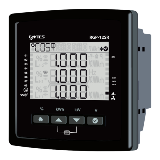
- Page 1 RGP Series 3 Phase Power Factor Controllers RGP-12SR SVC1 SVC2 SVC3 www.entes.com.tr...
- Page 2 Index 1. Introduction ...................... 8 1.1 General Specifications ................8 1.2 RGP Product Family ................... 8 1.3 Operati̇ ng Condi̇ ti̇ ons ................. 8 1.4 Led Introduction ..................9 1.5 Display Smiley View ................... 9 1.6 Front Panel View ..................10 1.7 Key Functions .....................
- Page 3 3.1.3.4 Generator Target CosΦ ..............22 3.1.3.5 Three-phase On Delay ..............24 3.1.3.6 Three-phase Off Delay ..............24 3.1.3.7 Single phase Delay ..............24 3.1.3.8 Discharge Time ................24 3.1.3.9 Power factor correction Manual Step ......25 3.1.3.10 Power factor correction Manual SVC Step ........ 25 3.1.3.11 Power factor correction Reading Day ........
- Page 4 3.3.5 Power factor correction Last Month ............. 37 3.4 Power ......................38 3.4.1 Power Cos Φ ..................38 3.4.2 Power Factor ..................38 3.4.3 Total Power ..................38 3.4.4 Active Power ..................39 3.4.5 Reactive Power .................. 39 3.4.6 Apparent Power .................. 39 3.5.1.
- Page 5 Copyrights of this manual are reserved and it is strictly prohibited to use any part or content of it. Read this manual before commissioning and operating the RGP Series products by ENTES. The information given below is important to avoid problems that may emerge during installation and use.
-
Page 6: Safety Warnings
Safety Warnings • Installation, commissioning, maintenance and operation of the product must be carried out by authorized specialists. The manufacturer is not responsible for damages emerging from failure to follow the instructions. • Do not install the product if it has been damaged during transportation. Contact your Sales Representative. - Page 7 Double insulated - The user will not be subject to electric shock even if they touch low voltage areas when the product is energized. (Display, Buttons, Communication, Battery) Ground Connection is not required. Category 3 - Electronic circuit that can be used CAT III in measurement and testing systems.
-
Page 8: General Specifications
White backlight) (RGB Backlight *W code models RGP-12S ● ● have White backlight) (RGB Backlight *W code models RGP-12SR ● ● ● have White backlight) Table 1: RGP Product Family 1.3 Operating Conditions Ensure that the operating conditions given in the table below are provided to obtain the desired efficiency from your product. -
Page 9: Led Indicator
1.4 LED Indicator LED Color LED Status Description Stable Alarm Available Green Flasher Communication Available Stable No Problems Blue Stable Generator Enabled Yellow Stable Warning Available Table 3: Notification LED 1.5 Display Smiley View The messages that your device can give and the table of the Alarm / Warning status are as follow. Below you can see in which situations “Smiley Job”... -
Page 10: Front Panel View
If the product is in Smiley mode and if there is an alarm or warning screen (back screen light on or off), press any key to display the alarm or warning messages for your product. There will be description of the warning or alarm in the navigation section of your product, alarm or warning indication on the screen, and the number of warnings or alarms on the lower bar. -
Page 11: Key Functions
(%) Figure 1: Key Functions Your ENTES RGP product consists of 8 main menus. You can use the Up and Down keys to navigate the menu or access the desired settings menu. 1.7.1 Generator, Temperature, Alarm and Fan Indicators Generator ( G ): If the the Generator symbol on the product is active, this means that the Generator is enabled. - Page 12 1.7.2 Energy Shortcut Menu Press and hold the Up button for 2 seconds to display the active import energy menu screen. You can use the Up and Down keys to access the instant parameters for Enr-AI (Active Import Energy), ENR- AE (Active Export Energy), Enr- r (inductive), Enr- r (capacitive), Enr- s (Apparent Energy), Enr- JEn (Generator Energy)of your system.
-
Page 13: Tutorial Mode
1.7.5 Tutorial Mode The Tutorial Mode informs you about the meanings of the functions of the Smiley mode. During first set-up of your product, it is displayed on the screen right after language selection. If you want to see the Tutorial Mode while the product is operating, press and hold the Up and Down keys simultaneously for 2 seconds to enable the Tutorial Mode and display descriptions of the key functions. - Page 14 1.9 Connecti̇ on Di̇ agram IND3 T(L3) IND2 S(T2) INDI R(L1)
- Page 15 Follow the steps below respectively to make electrical connections of your product. For the product to operate properly, insert the three phase, one neutral cable and current cables of the three phases into the relevant inputs on the product. Make the step connections as described in the connection diagram. Make sure that you connect a three-phase capacitor to the reference step here.
-
Page 16: Using The Product
2.Using the Product 2.1 Setup When you switch on the product for the first time, you will see the language selection menu and the Tutorial Mode will be active. After the Tutorial Mode screens, you will proceed to the configuration screens for Region Selection, Time Setting, Date Setting, CT Primary, CT Secondary, Target CosΦ, Reference Step settings respectively, you will enter them in accordance with the required information and proceed to the Auto Setup screen. - Page 17 3.1.1 User Settings Menu In the User Settings submenu, you can set language, light, Smiley mode, security and password. To exit the submenus, press HOME. You will be asked if you want to save the changes or not. Use the Up and Down keys to select Yes or No, and press OK to save the setting.
- Page 18 3.1.2.1 Connection Correction It allows you to perform connection correction under the setup menu at a desired time. You must connect 3 phase capacitor to referance step. The cpacitor to referance step. The PFC switchs on/ off the ref step for the connection correction operation. If the operation is successful it will start to the auto setup.
- Page 19 3.1.2.3 System Frequency Settings To change the system nominal frequency, you can go to Settings-Setup-SETUP NOM HZ submenu. 50 Hz or 60 Hz is selected to exit the submenus after you have made the desired changes, press HOME twice. Use the Up and Down keys to select one of the options your product is displaying, and press OK to save the setting.
- Page 20 3.1.2.5 Auto Setup SVC Setting When you start the automatic setup menu, the product will connect to your driver to start the recogni- tion process for single phase shunt reactors connected to the driver. 3.1.2.6 Step Setting It is the submenu where the steps used, step type, step connection and the total power of the step is entered.
- Page 21 3.1.2.7 Driver Setting (on SR models only) It is the section where the values of reactors connected to the driver are set manually. 3.1.3 Power factor correction Settings Settings related to power factor correction are below. If your user security setting is enabled, you should enter the password before accessing the submenus.
- Page 22 3.1.3.2 Power factor correction Mode It is the menu where the power factor correction process applied is selected. Eco mode (Eco) remains within the alarm limits determined by the user to ensure the lowest contactor switching and lowest step use. Sensitive mode (Sens) is the mode that offers the closest solution to the targeted cosΦ...
- Page 23 If you select `no` the wizard will finish. if you select “off” the steps will be switch off. For (+) the symbol is used. For the (-) symbol is used.
-
Page 24: Discharge Time
3.1.3.5 Three-phase On Delay It indicates the time required for three-phase capacitor taking and three-phase reactor release. Enter a value between 1 and 1800 (in seconds). The factory setting is 10 seconds. 3.1.3.6 Three-phase Off Delay It indicates the time required for three-phase capacitor off and three- phase reactor on. -
Page 25: Communication Settings Menu
3.1.3.9 Power factor correction Manual Step It is the menu where steps are switched on/off manually. 3.1.3.10 Power factor correction Manual SVC Step It is the step where the powers of driver reactors are switched on/off manually. 3.1.3.11 Power factor correction Reading Day It is the menu where the day on which your electricity bill is defined on the product. - Page 26 3.1.4.1 Modbus Setting Modbus RTU settings of the device are performed in this menu. Modbus address, bit rate and parity bit of the product are set in this menu. Modbus Address: This parameter can be set to a value between 1 and 247. The value set must be unique on the line where the product is found.
- Page 27 The parity bit can be set to none, odd or even. The value of this parameter Parity Bıt: must be same as the value in the software you use to communicate with the product. Otherwise, you cannot communicate with the product. 3.1.5 Alarms Menu Alarms menu is where alarms are programmed.Step alarm, step warning values are entered as a % value.
- Page 28 3.1.5.2 Inductive Rate Alarm This alarm occurs when the inductive power factor rate exceeds the (last 7 days) % ratio set by the user. It continues until the alarm condition is eliminated. 3.1.5.3 Inductive Rate Warning This warning occurs when the as power factor correction rate exceeds the rate (last 7 days) set by the user.
- Page 29 3.1.5.6 Value Loss Alarm This alarm occurs if the power of you capacitor is under the limit of your alarm. Ex: your original capacity is 100 kVAr. You set the alarm %30, when value becomes to 30 kVAr it gives alarm. 3.1.5.7 Value Loss Warning This warning occurs if the power of you capacitor is under the limit of your alarm.
- Page 30 3.1.5.9 Contactor Service Life Alarm This alarm occurs when the rate of the contactor switching countexceeds the ratio set by the user. 3.1.5.10 Voltage Alarm You can set voltage alarm on the device first of all you should enter the high threshold than you can set the hysteresis can be set by %, the device will recover if that amount of lower value is detected.
- Page 31 3.1.5.11 THDV Alarm You can set harmonic alarm on the device. First of all you should enter high thresold that You can set the hysteresis can be set by %, the device will recover if that amount of lower value is detected. Also on delay parameter should be set and the device checks if in that time interval the condition is available it give the alarm.
-
Page 32: Temperature Alarm
3.1.5.13 Temperature Alarm: You can set temperature alarm(Only for model’s which includes internal temperature sensor). You should enter high value and low value. You can enable step protection, switch off your steps for protecting them. 3.1.5.14 Special Alarm There are Active and Passive options in the menu. You can active an alarm and program it with the wizard. - Page 33 3.1.6 Time Menu It is composed of the screens where the time zone, date and time values are set. If your user security setting is enabled. 3.1.6.1 Time Zone On this screen, the user can change the time range of the product. The time zone can be set between -12:00 and 14:30 with half-an-hour intervals.
- Page 34 3.1.7 System Menu In the System Settings menu, you can display information of the software, hardware and serial number of your product. 3.1.7.1 Software Version It is the menu where you can display the software version of your product. 3.1.7.2 Hardware Version It is the menu where you can display the hardware version of your product.
-
Page 35: Restore Factory Settings
3.1.8 Reset Menu If your user security setting is enabled, you should enter the password before accessing the submenus. 3.1.8.1 Restore Factory Settings It is the menu where you can return to the factory settings of your product. Enter the password and press “OK”. If you say Yes to the confirmation question, the product will return to factory settings. - Page 36 3.2COS Fi (Φ) Menu 3.3 Power factor correction Menu It is the menu where you can see the inductive rate, capacitive rate and active consumptions for today, yesterday, last month and the last 7 days. 3.3.1 Power factor correction Today It is the menu where you can display the total inductive power factor correction rate, capacitive power factor correction rate values for today.
- Page 37 3.3.2 Power factor correction Last 7 Days It is the menu where you can display the total inductive power factor correction rate, capacitive power factor correction rate. 3.3.4 Power factor correction This Month It is the menu where you can display the total inductive power factor correction rate, capacitive power factor correction rate.
- Page 38 3.4 Power 3.4.1 Power Cos Φ You can display Cos Φ of each phase separately. If you wait for 2 seconds in the menu, the product will show you the total Cos Φ value in the navigation section. 3.4.2 Power Factor You can display the power factor of each phase separately. If you wait for 2 seconds in the menu, the product will show you the total PF value in the navigation section.
-
Page 39: Reactive Power
3.4.4 Active Power Active powers on the phases are displayed on this screen. Press OK to enter the menu so you can display minimum and maximum values for the phases. If you wait for 2 seconds in the menu, the product will show you the total Active Power value in the navigation section. 3.4.5 Reactive Power Reactive powers on the phases are displayed on this screen. - Page 40 3.5 Energy It is the menu where index values are displayed. 3.5.1. Active Import Energy (AI): From the network 3.5.2. Active export energy (AE): From the network 3.5.3. Inductive reactive energy (Enr r): From the network 3.5.1. Active Import Energy (AI) 3.5.2.
- Page 41 3.5.4. Capacitive reactive energy (Enr r) : From the network 3.5.5. Apparent energy (S) : From the network 3.5.6. Generator Energy (Gen) If the generator input is active, other energy counters does not increase. The active energy is added to this energy meter. 3.5.4.
- Page 42 3.6 Measurements Phase-phase, phase-neutral voltages, current values of 3 phase and the 3.6 Measurements frequency, temperature value measured are displayed on this screen. 3.6.1 Voltage (Phase-Neutral) 3.6.1 Voltage (Phase-Neutral) At the menu phase-Neutral voltage values and at the sub menus 3.6.2 Voltage (Phase-Phase) maximum-minimum values for each phase are displayed on this screen.
- Page 43 3.6.4 Frequency It is the menu where you can see the operating frequency of the product. 3.6.5 Temperature: You can see the internal temperature on the screen. 3.6.4 Frequency 3.6.4 Temperature 3.7 Harmonics 3.7.1 Current Har- monics 3.7 Harmonics 3.7.1 Current Harmonics When you are in the current harmonics menu, you can press OK to proceed to the details menu and you can use Up and Down keys to display the current harmonics on the system up to the 31st harmonic.
-
Page 44: Voltage Harmonics
3.7.2 Voltage Harmonics When you are in the voltage harmonics menu, you can press OK to proceed to the details menu and you can use Up and Down keys to display the voltage harmonics on the system up to the 31st harmonic. - Page 45 3.8 Messages It is the menu where the alarm messages of the system are stored and where you can later display these messages. The navigation line gives you the definition of the alarm, the first line on the screen indicates if the message is an alarm or a warning. The second number in the line below shows the number of the messages on the system, and the first number shows which message amongst them you are displaying.
- Page 46 This message shows that any phase THDV (Total harmonic Distortion) value exceed the alarm limit. This message shows that any phase THDI (Total harmonic Distortion) exceed the alarm limit. This message shows that the internal temperature exceed the temperature alarm limit.
- Page 47 This screen shows that the SVC thermic is opened. This screen shows that the user alarm( Which you can program manually) exceed it’s alarm limit. This screen shows that the capacitive rate exceed’s the alarm limit.
- Page 48 This screen shows that the inductive rate exceed’s the warning limit. This screen shows that the capacitive rate exceed’s the warning limit. This screen shows that the inductive rate exceed’s the warning limit.
- Page 49 This screen shows that your capacitors are not enough for your inductive reactive power. Even if the PFC switch on all the capacitors the system is on inductive side. This message shows that your reactors are not enough for your capacitive reactive power. Even if the PFC switch on all the reactors the system is still on capacitive side.
- Page 50 This message shows that any capacitor value is under the alarm, warning limit. This message shows that any contactor’s life exceed the alarm, warning limit. This message shows that the capacity loss of your capacitor is exceed’s the alarm, warning limit.
- Page 51 This message shows that the contactor life exceed’s the alarm limit. This message shows that the contactor life exceed’s the warning limit.
-
Page 52: Maintenance
4 Maintenance Keep your product away from water and humidity. Before carrying out maintenance tasks on your product, disconnect your product from power sources and clean it with a dry cloth only. Keep your product away from water, chemical solvents etc. It is recommended to have cable connections checked by an authorized technical personnel annually. - Page 53 7 Annexes 7.1 Mechanical and Environmental Conditions Dimensions 144 x 144 mm Maximum Depth (Inside the 60 mm Switchboard) Panel Section Dimension 138 x 138 mm Installation Vertical Panel Installation IP 54 (Front Panel) Box Protection IP 20 (From the rear side) Segment LCD Display Color...
- Page 54 7.2.2Phase Current Parameter Unit Description Range Sensitivity Max. Value I1, I2, I3 Phase Current 0.005 - 6A ±0.5% 10 kA THDI Total Harm. Current Dist. 0 – 200% ± 1% 1000% Harmonic Current Amplitude 2. – 31. ± 1% 10 kA I Harmonic Degree Harmonic Current Amplitude...
- Page 55 7.2.4Energy Parameter Unit Description Range Sensitivity Max. Value Imp Active Energy 0 – 2^64 ± 1% 2^64 Wh VArh Imp Reactive Energy 0 – 2^64 ± 1% 2^64 VArh VArh Exp Reactive Energy 0 – 2^64 ± 1% 2^64 VArh Apparent Power 0 –...
- Page 56 7.3 Step Parameter Unit Description Range Sensitivity Max. Value Power of Steps 999.9 kVAr + Qs1 ... Qs12 VAr ± 3% -999.9 + 9.999 kVAR 9.999 kVAR Step Change Ts1 ... Ts12 0 – 2^32 2^32 Counter Hs1 ... Hs12 h Step Operating Time 0 –...
- Page 57 ENTES Elektronik Cihazlar Imalat ve Ticaret A.S. Adr: Dudullu OSB; 1. Cadde; No:23 34776 Umraniye - ISTANBUL / TURKIYE Tel: +90 216 313 01 10 Fax: +90 216 314 16 15 E-mail: contact@entes.eu Web: www.entes.eu Call Center Technical Support: 0850 888 84 25...
Need help?
Do you have a question about the RGP-12SR and is the answer not in the manual?
Questions and answers