Table of Contents
Advertisement
Quick Links
POWER FACTOR CONTROLLER
RG3-15C/CS/CL/CLS
1.1
General Information ............................................................................................................................................2
1.2
Front Panel .................................................................................................................................................................2
1.3
Rear Panel ..............................................................................................................................................................4
2.1
Commissioning of RG3-15C/CS/CL/CLS ..........................................................................................................................5
2.2
Step Sequence Process ...........................................................................................................................................5
3.1
Manual Operation, Automatic Capacitor Recognition Mode and Automatic Connection Recognition Mode...........6
3.2
3.3
Selection of Proper Switching Sequence.........................................................................................................................8
3.4
Switching on&off Time for Capacitor Steps and Discharge Time Settings.................................................................8
3.5
Power Value and Connection Type Settings for Capacitors ........................................................................................10
3.6
Current and Voltage Transformer Ratio Settings .......................................................................................................12
3.7
Reset Settings .....................................................................................................................................................14
3.8
Alarm Settings .....................................................................................................................................................15
3.9
Resetting the Energy Counters and Entering the Energy Values..................................................................................20
3.10 Computer Communication Settings .................................................................................................................................21
3.11 Password Activation and Change Settings .............................................................................................................23
Currents, Active Powers, Total Active Powers ...........................................................................................................26
Reactive Powers, Total Reactive Powers, Apparent Powers, Total Apparent Powers......................................27
Error Codes ......................................................................................................................................................28
Error Messages ................................................................................................................................................29
Capacitor Calculation Table ............................................................................................................................................35
Technical Features ..............................................................................................................................................36
Menu Map .............................................................................................................................................................
SUMMARY
Value Setting ....................................................................................................................7
, Voltages ................................................................................................................................25
A5372b/Rev.3
1
1
2
5
5
25
29
30
Advertisement
Table of Contents

Subscribe to Our Youtube Channel
Related Manuals for Entes RG3-15C


Summary of Contents for Entes RG3-15C
-
Page 1: Table Of Contents
Important Note for System Connection 1. INTRODUCTION General Information ............................2 Front Panel .................................2 Rear Panel ................................4 2. INSTALLATION OF RG3-15C/CS/CL/CLS Commissioning of RG3-15C/CS/CL/CLS ..........................5 Step Sequence Process ............................5 3. SETTINGS Manual Operation, Automatic Capacitor Recognition Mode and Automatic Connection Recognition Mode...6... -
Page 2: Precautions For Safe Use And Installation
POWER FACTOR CONTROLLER RG3-15C/CS/CL/CLS ATTENTION! Precautions for Safe Use and Installation Important Note for System Connection. Generator Input Connection “Cosj” “Cosj2”... -
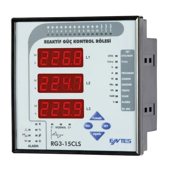
Page 3: Introduction
POWER FACTOR CONTROLLER RG3-15C/CS/CL/CLS 1.2 Front Panel 1. INTRODUCTION 1.1 General Information AUTO RG3-15C/CS/CL/CLS ile Yapýlabilecek Ölçümler 1.2.a Button Functions DIMENSIONS DOWN Type PR16 (144x144) 34.5 138.4 Excessive force can damage the device. Turn the screw into the terminals and tighten until the... - Page 4 POWER FACTOR CONTROLLER RG3-15C/CS/CL/CLS 1.2.b Front Panel Functions 14. PROGRAM / I LED PROGRAM 15. TIME / W LED TIME AUTO 16. Capacitors/VAr LED CAPACITORS 17. NETWORK/VA LED NETWORK 1. L1 2. L2 3. L3 4. Up Button 18. RESET / HAR LED RESET 5.
-
Page 5: Rear Panel
Don’t energise the device without making sure that the connections are correct. A 3-phase capacitor must always be connected to the first step. At least 3 single phase capacitors must be connected to the steps for RG3-15C/CS. -
Page 6: Installation Of Rg3-15C/Cs/Cl/Cls
POWER FACTOR CONTROLLER RG3-15C/CS/CL/CLS 2.1 Commissioning of RG3-15C/CS/CL/CLS Warnings: Phase current should not be equal to zero in order to let the device to detect the connection error. Refer to page 10 - Setting of the capacitor’s connection and power values NOTE: PFC decreases the switching on&off time to 3 seconds in... -
Page 7: Manual Operation, Automatic Capacitor Recognition Mode And Automatic Connection Recognition Mode
POWER FACTOR CONTROLLER RG3-15C/CS/CL/CLS 3.1.b Automatic Capacitor Recognition Mode Setting “UP” “DOWN” “SET” NOTE: If there are other loads than compensation connected to the “ESC” system, the device may not find the connection at the first try and may need several tries. However, if the device is unable to complete the automatic connection process step calculation process shouldn’t be... -
Page 8: Target Cos J And Cos J2 Value Setting
POWER FACTOR CONTROLLER RG3-15C/CS/CL/CLS 3.1.c Automatic Connection Recognition Mode 3.2 Target Cosj and Target Cosj2 Value Settings Setting Capacitive Inductive Cosj 3.2.a Inductive / Capacitive and Cosj2 Setting Capacitive, Ýnductive NOTE Cosj2 value can be set the same way from Cosj2 menu. -
Page 9: Selection Of Proper Switching Sequence
POWER FACTOR CONTROLLER RG3-15C/CS/CL/CLS 3.3 Selection of Proper Switching Sequence SAUE “ESC” “SAVE SEt yES” “SET” “ESC” NOTE: In the 10th program(PS-10), power values and connection types(except the first step) of the single phase P R O G R A M S E Q U E N C E capacitor steps(r, s, t, rst, oFF) can be set by user. - Page 10 POWER FACTOR CONTROLLER RG3-15C/CS/CL/CLS 3.4.b Switch-Off Delay Time Setting “SET” “UP/DOWN” “SET” “SET” “SET” “UP/DOWN” “SET” “ESC” “UP/DOWN” “ESC” SAUE SAUE “ESC” “SAVE SEt yES” “ESC” “SAVE SEt yES” “SET” “SET” “ESC” “ESC”...
-
Page 11: Power Value And Connection Type Settings For Capacitors
POWER FACTOR CONTROLLER RG3-15C/CS/CL/CLS 3.4.c Discharge Time Setting 3.5 Power Value and Connection Type Settings for Capacitors “R, S, T, off” Note : For the first capacitor step. There isn’t a connection type setting. ”RST” connection type always must be selected because first capacitor step is used to detect correct connection. - Page 12 POWER FACTOR CONTROLLER RG3-15C/CS/CL/CLS 3.5.b Second Step Capacitor Setting “SET” “UP/DOWN” “RST” “SET” “SET” “SET” “UP/DOWN” “UP/DOWN” “ESC” “r”, “S”, “t” “rSt” “oFF” NOTE: If the 10th program is selected, capacitor powers can be set separately for each capacitor step. However; if any program except PS-10 is selected, only first capacitor steps Note: After automatic calculation of the capacitors, if “oFF”...
-
Page 13: Current And Voltage Transformer Ratio Settings
POWER FACTOR CONTROLLER RG3-15C/CS/CL/CLS “SET” “UP/DOWN” “ESC” “oFF” “UP/DOWN” SAUE Note: After automatic calculation of the capacitors, if “oFF” is displayed in any step, it means that related capacitor could not be calculated, is defected or there is no connected capacitors in the related step. - Page 14 POWER FACTOR CONTROLLER RG3-15C/CS/CL/CLS 3.6.b Voltage Transformer Ratio Setting For Example: NOTE: Be aware that this value is entered as a ratio, not VT primary or secondary value. “UP/DOWN” “UP/DOWN” “SET” “SET” “SET” “SET” “ESC” “UP/DOWN” “ESC” “SET” SAUE “ESC”...
-
Page 15: Reset Settings
POWER FACTOR CONTROLLER RG3-15C/CS/CL/CLS 3.7 Reset Operation Settings 3.7.b Reactive/Active Ratio Reset Setting 3.7.a Alarm Reset Operation Setting “yES” NOTE: When an alarm occurs, the alarm relay switches on and the related alarms LED turns on and the alarm code is displayed. Even if alarm conditions disappear, the alarm relay will stay switched on. -
Page 16: Alarm Settings
POWER FACTOR CONTROLLER RG3-15C/CS/CL/CLS 3.8 Alarm Settings overvoltage, reactive/active ratio “SET” 3.8.a Overvoltage Alarm Setting V> 3.8.a.a Overvoltage Setting “SET” “ESC” NOTE: SAUE “UP/DOWN” “ESC” “SAVE SEt yES” “SET” “ESC” 3.8.a.b Overvoltage Delay Time Setting “SET” “DOWN” “SET”... - Page 17 POWER FACTOR CONTROLLER RG3-15C/CS/CL/CLS “SET” “SET” UP DOWN “UP/DOWN” “on” “of” “SET” “UP/DOWN” “SET” “ESC” “ESC” SAUE SAUE “ESC” “SAVE SEt yES” “ESC” “SAVE SEt yES” “SET” “SET” “ESC” “ESC” 3.8.b Reactive / Active Ratio Setting 3.8.a.c Switch On or Switch Off Setting of Capacitor Steps for Overvoltage Alarm Setting 3.8.b.a...
- Page 18 POWER FACTOR CONTROLLER RG3-15C/CS/CL/CLS SAUE “SET” “ESC” “SAVE SEt yES” “SET” “ESC” 3.8.b.b Inductive Ratio Setting “UP/DOWN” “Alr rAtE CAP” “rAtE Ind” “UP/DOWN” “SET” “SET” “SET” “SET” “SET” “SET” “UP/DOWN” “ESC” “ESC”...
- Page 19 POWER FACTOR CONTROLLER RG3-15C/CS/CL/CLS SAUE “ESC” “SAVE SEt yES” “SET” “ESC” “SET” 3.8.d Harmonic Setting 3.8.d.a Overvoltage Harmonic Setting “SET” “SET” “UP/DOWN” “SET” SAUE “SET” “ESC” “SAVE SEt yES” “SET” “ESC” “UP/DOWN”...
- Page 20 POWER FACTOR CONTROLLER RG3-15C/CS/CL/CLS 3.8.d.b If “on” option is selected: Harmonic Alarm Delay Time Setting If “of” option is selected: “UP/DOWN” “UP/DOWN” “SET” “SET” “SET” UP DOWN “UP/DOWN” “on” “of” SAUE “SET” “UP/DOWN” “ESC” SAUE “ESC” “SAVE SEt yES” “SET”...
-
Page 21: Resetting The Energy Counters And Entering The Energy Values
POWER FACTOR CONTROLLER RG3-15C/CS/CL/CLS 3.9 Resetting the Energy Counters and Entering the Energy Values “SET” 3.9.a Entering the Energy Values Note: SAUE “SET” “ESC” “SAVE SEt yES” “SET” “ESC” 3.9.b Resetting the Energy Values “UP/DOWN” “SET” “SET” “UP/DOWN” “A-I” “SET”... -
Page 22: Computer Communication Settings
POWER FACTOR CONTROLLER RG3-15C/CS/CL/CLS “SET” “UP/DOWN” “yES” “no” “SET” SAUE “yES” “no” “UP/DOWN” “SET” “ESC” “SAVE SEt yES” “SET” “ESC” SAUE 3.9.c Conditioning the Energy Counters to Work with the Generator Input “ESC” “SAVE SEt yES” “SET” “ESC” 3.10 PC Communication Settings (RS-485) NOTE: Computer communication feature is only available for RG3-15CS/CLS models. - Page 23 POWER FACTOR CONTROLLER RG3-15C/CS/CL/CLS 3.10.b Baud Rate Setting “SET” “UP/DOWN” “SET” “SET” “SET” “SET” “ESC” “UP/DOWN” “SET” SAUE “SET” “ESC” SAUE “ESC” “SAVE SEt yES” “SET” “ESC” “ESC” “SAVE SEt yES” “SET” “ESC”...
-
Page 24: Password Activation And Change Settings
POWER FACTOR CONTROLLER RG3-15C/CS/CL/CLS 3.11 Password Activation and Change Settings 3.10.c Parity Setting “no”, “odd” “EVEn” Note: Factory default value for pin code is “1234” and it is not activated. 3.11.a Pin Activation “UP/DOWN” “UP/DOWN” “SET” “SET” “UP/DOWN” “SET” “SET”... - Page 25 POWER FACTOR CONTROLLER RG3-15C/CS/CL/CLS NOTE: “UP/DOWN” “SET” “ESC” “SET” “SET” “UP/DOWN” “on” “of” “SET” “SET” “ESC” “SET” SAUE “ESC” “SAVE SEt yES” “SET” “SET” “ESC” NOTE: If you do not save your changes, they will not be valid. NOTE: After the settings in the menu are done, the changed settings are selected and the menu can be shown by pressing the “SET”...
-
Page 26: Displaying Of Instantaneous Values
POWER FACTOR CONTROLLER RG3-15C/CS/CL/CLS Total Cosj 4. DISPLAYING OF INSTANTANEOUS VALUES Cosj “DOWN” “UP” “DOWN” “SET” 1.000 “ESC” -.947 Cosj Voltages Cosj “UP/DOWN” “SET” “SET” 225.5 -.912 228.7 0.973 22 3 .4 0.945 Cosj “SET” “SET”... -
Page 27: Currents, Active Powers, Total Active Powers
POWER FACTOR CONTROLLER RG3-15C/CS/CL/CLS Currents Active Powers “UP/DOWN” “UP/DOWN” “SET” “SET” 225.5 25.87 228.7 32.56 22 3 .4 18.93 “SET” “SET” Total Active Powers “DOWN” Note: The dot at the most right digit of the third display indicates that the displayed value is export value. -
Page 28: Reactive Powers, Total Reactive Powers, Apparent Powers, Total Apparent Powers
POWER FACTOR CONTROLLER RG3-15C/CS/CL/CLS Reactive Powers Apparent Powers “UP/DOWN” “UP/DOWN” “SET” “SET” 225.5 225.5 228.7 228.7 22 3 .4 22 3 .4 “SET” “SET” Total Reactive Powers Total Apparent Power “DOWN” “DOWN” Note : The dot at the most right digit of the third display indicates that the displayed value is capacitive reactive power. -
Page 29: Active Import Energy, Active Export Energy, Inductive Reactive Energy, Capacitive Reactive Energy, Error Codes
POWER FACTOR CONTROLLER RG3-15C/CS/CL/CLS Active Import Energy Capacitive Reactive Energy “E” “UP/DOWN” “I” E-00 1-20 4035 3385 386.2 706.8 Active Export Energy Capacitive/Active ratio “DOWN” Capacitive/Active ratio Refer to page 17 - Inductive ratio setting “E” Note: When you reset the reactive/active ratio, the value in the first display will be reset and updated continiously. -
Page 30: Appendix
POWER FACTOR CONTROLLER RG3-15C/CS/CL/CLS 5. APPENDIX ALARM CODES DESCRIPTION REASON Angle degree between phase voltages doesn’t equal to 120° Neutral and Voltage terminal connections are incorrect. Reverse phase sequence Voltage terminal connections are in counter-clockwise direction One or more phase voltages don’t exist... -
Page 31: Register Table
POWER FACTOR CONTROLLER RG3-15C/CS/CL/CLS REGISTER TABLE REGISTER TABLE ADDRESS (HEX) PARAMETER FORMAT MULTIPLIER UNIT FUNCTION... - Page 32 POWER FACTOR CONTROLLER RG3-15C/CS/CL/CLS REGISTER TABLE ADDRESS (HEX) PARAMETER FORMAT MULTIPLIER UNIT FUNCTION...
- Page 33 POWER FACTOR CONTROLLER RG3-15C/CS/CL/CLS REGISTER TABLE NO ADDRESS (HEX) PARAMETER FORMAT MULTIPLIER UNIT FUNCTION...
- Page 34 POWER FACTOR CONTROLLER RG3-15C/CS/CL/CLS REGISTER TABLE ADDRESS (HEX) PARAMETER FORMAT MULTIPLIER UNIT FUNCTION...
- Page 35 POWER FACTOR CONTROLLER RG3-15C/CS/CL/CLS REGISTER TABLE ADDRESS (HEX) PARAMETER FORMAT MULTIPLIER UNIT FUNCTION...
-
Page 36: Capacitor Calculation Table
POWER FACTOR CONTROLLER RG3-15C/CS/CL/CLS CAPACITOR CALCULATION TABLE... -
Page 37: Technical Features
POWER FACTOR CONTROLLER RG3-15C/CS/CL/CLS Technical Features Please look at the rear label of the device. Factory Set Values Only available for RG3-15CS/CLS...
Need help?
Do you have a question about the RG3-15C and is the answer not in the manual?
Questions and answers