Table of Contents
Advertisement
Quick Links
POWER FACTOR CONTROLLER
RG-6T
1. INTRODUCTION
1.1 About User Manual
This User Manual is designed to help you for quick installation of RG-6T. Before installation
and operation, please read this section very carefully.
1.2 Precautions for Safe Use and Installation
- Failure to follow those instructions will result in death or serious injury.
- Disconnect all power before working on equipment.
- When the device is connected to the network, do not remove the back panel.
- Do not try to clean the device with solvent or the like. Only clean the device
with dried cloth.
- Verify correct terminal connections when wiring.
- Electrical equipment should be serviced only by your component seller.
- Only for rack panel mounting.
- An F type fuse must be used and its current limit value must be 6A.
- No responsibility is assured by ENTES A.S or any of its subsidiaries
for any consequences arising out of the use of this material.
2. GENERAL
Power Factor Controllers are used for measurement and control of power factor control units
for central reactive power compensation. The Power Factor measured by RG-6T is compared
with the set point values and in order to provide necessary compensation, Power Factor
Controller switches capacitor banks ON and OFF automatically. RG-6T is a microcontroller
relay, designed for above application in 144x144 and 96x96 (only RG-6T) case for flush
mounting with rear plug-in connectors. In addition to displaying the system's Cosϕ in Automatic
Operating Mode, RG-6T displays the RMS values of Voltage(V) and Current (I), Active
Power (W), Reactive Power (VAr) and Apparent Power (VA) of measuring phase.
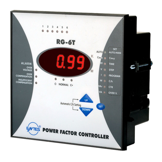
3. FRONT PANEL SPECIFICATIONS
20
19
18
17
16
15
On the front panel of RG-6T, there are warning lights, display and 3 buttons for settings.
3.1 Buttons and Lights
1. 1,2,.........,12
: Shows the status of each capacitor steps.
2.SET Menu
: Shows the Menu options that correspond to the lights.
3. AUTO/MAN Light : If this light is continuously ON, RG-6T is in Automatic Mode. If it is
blinking, RG-6T is in Manual Mode. By pressing SET button 3
seconds, you enter to Menu and change operating Mode . (Refer
to: 5.1)
4. Cosϕ Light
: By pressing SET button 3 seconds ; Cosϕ Adjustment can be made
by selecting this light. (Refer to: 5.3).
In Automatic Mode, when Cosϕ light is selected by pressing UP
and DOWN buttons, system's Cosϕ and ind/cap state is displayed.
(Refer to: 5.10)
5.TIME/PF Light
: By pressing SET button 3 seconds; you enter to Menu and Step
Time adjustment is made by selecting this light. (Refer to: 5.4)
In Automatic Mode, when this light is selected by pressing UP and
DOWN buttons, system's Power Factor is displayed. (Refer to: 5.11)
6.STEP/V Light
: By pressing SET button 3 seconds; you enter to Menu and Step
Number adjustment is made by selecting this light. (Refer to:5.5)
In Automatic Mode, when this light is selected by pressing UP and
DOWN buttons phase voltage (V) is displayed. (Refer to:5.12)
7. PROGRAM/I Light: By pressing SET button 3 seconds; you enter to Menu and Power
Sequence adjustment is made by selecting this light. (Refer to:5.6)
In Automatic Mode, when this light is selected by pressing UP and
DOWN buttons phase current (I) is displayed (Refer to:5.12)
8.C/k - W Light
: By pressing SET button 3 seconds; you enter to Menu and Manual
C/k adjustment is made by selecting this light.(Refer to:5.7)
In Automatic Mode when this light is selected by pressing UP and
DOWN buttons, system's Active Power (W) is displayed.
(Refer to: 5.13)
9.CTR - VAr Light
: By pressing SET button 3 seconds; you enter to Menu and Current
Transformer Ratio adjustment is made by selecting this light.
(Refer to:5.8)
1
RG-6T
M
W
VAr
OVER V.
VA
10.Over V. /VA Light : By pressing SET button 3 seconds; you enter to Menu and Protection
11.UP Button
12.SET Button
13.DOWN Button
14.Automatic
C/k Setting
15. C+ Light
16. NORMAL Light : This light is ON when the targeted compensation is achieved.
17. C- Light
18.Insufficient
Compensation
Light
19.Over
Compensation
Light
20.Over Voltage
Light
21.K (Kilo) Light
22.M (Mega) Light : When this light is ON displayed value must be multiplied by 10
21
4. CONNECTION DIAGRAM
2
3
4
5
6
7
8
9
10
22
11
12
13
14
N
L3
L2
L1
Warnings:
a) Connection of a circuit breaker between the network and the power supply
input of the device is highly recommended.
b) Circuit breaker must be in close proximity to the device.
c) Circuit breaker must be marked as the disconnecting device for the equipment.
d) All used fuses must be FF type and the current values of the fuses must be
2A, 3A and 6A.
1
In Automatic Mode when this light is selected by pressing UP and
DOWN buttons, system's Reactive Power (VAr) is displayed.
(Refer to: 5.14)
of Capacitor Steps Against Over Voltage function is made by selecting
this light. (Refer to:5.9)
In Automatic Mode when this light is selected by pressing UP and
DOWN buttons, system's Apparent Power (VA) is displayed.
(Refer to: 5.15)
: To move up in the Menu.
: Enter button for different settings and values.
: To move down in the Menu.
: Automatical C/k adjustment is started by pressing UP and DOWN
buttons together at the same time. (Refer to:5.2)
: This light is ON when RG-6T switches capacitor steps on.
: This light is ON when RG-6T switches capacitor steps off.
: This warning light is ON when insufficient compensation occurs.
(Refer to:6.1.2)
: This warning light is ON when over compensation occurs.
(Refer to:6.1.3)
: This warning light is ON when over voltage occurs. (Refer to:6.1.1)
: When this light is ON displayed value must be multiplied by 1000.
Phase-Neutral Connection*
7
8
9 10 11
12 13 14
N
L3
L2
L1
1
2
3
4
5
6
Phase-Phase Connection*
15
16 17
18
19
20
21
22 23
24 25
26
27 28
C6
C1
C7
K
L
k
l
2 A
1
5
6
2
3
4
6
C12
Alarm Relay
11
12
3 A
.
Advertisement
Table of Contents

Related Manuals for Entes RG-6T


Summary of Contents for Entes RG-6T
- Page 1 : Shows the status of each capacitor steps. Phase-Phase Connection* 2.SET Menu : Shows the Menu options that correspond to the lights. 3. AUTO/MAN Light : If this light is continuously ON, RG-6T is in Automatic Mode. If it is 16 17 22 23 24 25 27 28 blinking, RG-6T is in Manual Mode.
- Page 2 1) Automatic Operating Mode: The capacitor steps are controlled by RG-6T, automatically. system is selected by pressing SET button. 2) Manual Operating Mode: the capacitor steps are switched on/off, manually. RG-6T returns to Automatic mode if any button is not pressed within 5 minutes. Mode selection is done as followed. DOWN A value between 2-1800 sec.
- Page 3 If the phase-neutral voltage of the L1 phase exceeds or equals to preset Over Voltage Current Transformer Primary Value is selected Value (between 240-275V), then RG-6T waits for 3 seconds. At the end of 3 seconds if by pressing SET button. Previously selected there is still over voltage, then OVER VOLTAGE LED turns on.
- Page 4 Now , depending on the power of the first step, C/k value is calculated very accurately by RG-6T. The calculated C/k value will automatically be stored in the memory. You can The C/k value is a threshold value for switching on/off the capacitor steps. C/k is the switch the load on.
Need help?
Do you have a question about the RG-6T and is the answer not in the manual?
Questions and answers