Table of Contents
Advertisement
Available languages
Available languages
Quick Links
FR
02-06 / 7-18 / 91-100
02-06 / 19-30 / 91-100
EN
02-06 / 31-42 / 91-100
DE
02-06 / 43-54 / 91-100
ES
02-06 / 55-66 / 91-100
RU
NL
02-06 / 67-78 / 91-100
IT
02-06 / 79-90 / 91-100
73502
V2
01/04/2022
VAS 821 005
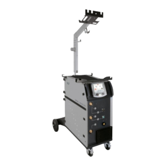
Générateur MIG/MAG
MIG/MAG welding machine
Schweissgerät für MIG/MAG
Equipo de soldadura MIG/MAG
Сварочный аппарат МИГ/МАГ
MIG/MAG lasapparaat
Dispositivo saldatura MIG/MAG
Advertisement
Table of Contents

Related Manuals for GYS VAS 821 005


Summary of Contents for GYS VAS 821 005
- Page 1 VAS 821 005 02-06 / 7-18 / 91-100 02-06 / 19-30 / 91-100 Générateur MIG/MAG MIG/MAG welding machine 02-06 / 31-42 / 91-100 Schweissgerät für MIG/MAG Equipo de soldadura MIG/MAG 02-06 / 43-54 / 91-100 Сварочный аппарат МИГ/МАГ MIG/MAG lasapparaat...
-
Page 2: Manuel D'utilisation
Manuel d’utilisation VAS 821 005 Notice originale M6x12 (x8) M6 (x8) M8x12 (x8) M6x12 (x4) M6x12 (x3) - Page 3 Manuel d’utilisation VAS 821 005 Notice originale M4x10 (x6) M6x12 (x3) POTENCE SEULE / BALANCING ARM ONLY / AUSLEGER / SOPORTE SOLO / КРОНШТЕЙН / STEUN ALLEEN / BRACCIO DI SOSTEGNO SINGOLO M6X12 M6X40 X 26...
- Page 4 Manuel d’utilisation VAS 821 005 Notice originale...
- Page 5 Manuel d’utilisation VAS 821 005 Notice originale RACCORD GAZ / GAS FITTINGS / GASANSCHLUSS / CONEXIÓN DE GAS / ГАЗОВОЕ СОЕДИНЕНИЕ / GAS AANSLUITING / COLLEGAMENTO GAS Couper le tuyau de gaz en 4 (Longueur au choix) Cut the gas hose in 4 (any length) Schneiden Sie den Gasschlauch in 4 Teile (beliebige Länge)
- Page 6 Manuel d’utilisation VAS 821 005 Notice originale Acier - Steel - Stahl - Acero - Staal - Aço Aluminium 90950 Inox - Stainless steel - Edelstahl Tube capillaire / Capillary Pipe / Kapillarrohr Gaine acier Gaine téflon Steel sheath Teflon sheath...
- Page 7 Manuel d’utilisation VAS 821 005 Notice originale AVERTISSEMENTS - RÈGLES DE SÉCURITÉ CONSIGNE GÉNÉRALE Ces instructions doivent être lues et bien comprises avant toute opération. Toute modification ou maintenance non indiquée dans le manuel ne doit pas être entreprise. Tout dommage corporel ou matériel dû à une utilisation non-conforme aux instructions de ce manuel ne pourra être retenu à la charge du fabricant.
-
Page 8: Sécurité Électrique
Manuel d’utilisation VAS 821 005 Notice originale Les bouteilles doivent être entreposées dans des locaux ouverts ou bien aérés. Elles doivent être en position verticale et maintenues à un support ou sur un chariot. Le soudage doit être proscrit à proximité de graisse ou de peinture. - Page 9 Manuel d’utilisation VAS 821 005 Notice originale Tous les soudeurs devraient utiliser les procédures suivantes afin de minimiser l’exposition aux champs électromagnétiques provenant du circuit de soudage: • positionner les câbles de soudage ensemble – les fixer avec une attache, si possible;...
-
Page 10: Installation Du Matériel
Manuel d’utilisation VAS 821 005 Notice originale TRANSPORT ET TRANSIT DE LA SOURCE DE COURANT DE SOUDAGE Ne pas utiliser les câbles ou torche pour déplacer la source de courant de soudage. Elle doit être déplacée en position verticale. Ne pas faire transiter la source de courant au-dessus de personnes ou d’objets. - Page 11 DESCRIPTION VAS 821 005 est un poste de soudure semi-automatique « synergique» ventilé pour le soudage (MIG ou MAG). Il est recommandé pour le soudage des aciers, des inox et des aluminiums et le brazing. Son réglage est simple et rapide grâce à son mode «synergique» intégral.
- Page 12 SOUDAGE SEMI-AUTOMATIQUE EN ACIER/INOX (MODE MAG) VAS 821 005 peut souder du fil acier de Ø 0.6 à 1.2 mm et acier inoxydable de Ø 0.8 à 1.2 mm (II-A). L’appareil est livré d’origine avec des galets Ø 0.6/0.8 et Ø 0.8/1.0 pour acier ou inox. Le tube contact, la gorge du galet, la gaine de la torche sont prévus pour cette application.
-
Page 13: Raccordement Gaz
SOUDAGE SEMI-AUTOMATIQUE ALUMINIUM (MODE MIG) VAS 821 005 peut souder du fil aluminium de Ø 0.8 à 1.2 mm (II-B). L’utilisation en aluminium nécessite un gaz spécifique argon pur (Ar). Pour le choix du gaz, demander conseil à un distributeur de gaz. Le débit de gaz en aluminium se situe entre 15 et 20 l/min selon l’environnement et l’expérience du soudeur. - Page 14 Manuel d’utilisation VAS 821 005 Notice originale DÉFINITION DES RÉGLAGES Unité Vitesse fil m/min Quantité de métal d’apport déposé et indirectement l’intensité de soudage et la pénétration. Tension Influence sur la largeur du cordon. Self Amortit plus ou moins le courant de soudage. À régler en fonction de la position de soudage.
- Page 15 Manuel d’utilisation VAS 821 005 Notice originale CYCLES DE SOUDAGE MIG/MAG Procédé 2T Standard : T hotstart I blackout Dstart Gas post-Flow T burn-back T crater Filler I crater Filler Soft-start À l’appui de la gâchette, le Pré-gaz démarre. Lorsque le fil touche la pièce, un pulse initialise l’arc, puis le cycle de soudage démarre. Au relâché de la gâchette, le dévidage s’arrête et un pulse de courant permet de couper le fil proprement suivi du Post gaz.
- Page 16 Manuel d’utilisation VAS 821 005 Notice originale Procédé 2T Pulsé : T hotstart T downslope T upslope I blackout Dstart Gas post-Flow T burn-back T crater Filler I crater Filler Soft-start À l’appui de la gâchette, le Pré-gaz démarre. Lorsque le fil touche la pièce, un pulse initialise l’arc. Puis, la machine commence par le HotStart, le Upslope et enfin, le cycle de soudage démarre.
- Page 17 Manuel d’utilisation VAS 821 005 Notice originale ÉNERGIE Mode développé pour le soudage avec contrôle énergétique encadré par un DMOS. Ce mode permet, en plus de l’affichage énergétique du cordon après soudage, de régler le coefficient thermique selon la norme utilisée : 1 pour les normes ASME et 0.6 (TIG) ou 0.8 (MMA/MIG-MAG) pour les normes européennes.
-
Page 18: Conditions De Garantie
Manuel d’utilisation VAS 821 005 Notice originale Tension d’arc trop basse ou trop haute. Voir paramètres de soudage. Contrôler et positionner la pince de masse au Particules d’étincelage très importantes. Mauvaise prise de masse. plus proche de la zone à souder. -
Page 19: Protecting Yourself And Others
Operating manual Translation of the original VAS 821 005 instructions WARNINGS - SAFETY INSTRUCTIONS GENERAL INSTRUCTIONS These instructions must be read and understood before using the machine. Any modification or maintenance that is not specified in the manual must not be carried out. - Page 20 Operating manual Translation of the original VAS 821 005 instructions Gas cylinders should be stored in open or well-ventilated areas. They should be kept in an upright position and kept on a cart or trolley. Welding should not be undertaken near grease or paint.
- Page 21 Operating manual Translation of the original VAS 821 005 instructions • do not position yourself between the welding cables and keep both welding cables on your same side, • connect the return cable to the workpiece, as close as possible to the area to be welded, •...
-
Page 22: Setting Up The Equipment
Operating manual Translation of the original VAS 821 005 instructions SETTING UP THE EQUIPMENT • Place the welding power source on a floor with a maximum inclination of 10°. • Provide sufficient space to ventilate the welding power source and access the controls. -
Page 23: Human-Machine Interface (Hmi)
DESCRIPTION The VAS 821 005 is a «synergic» semi-automatic welding machine, ventilated for welding (MIG or MAG). This machine is recommended for welding steel, stainless steel, aluminium and the brazing. Its adjustment is quick and easy with its «synergic» mode. -
Page 24: Loading The Filler Wire
SEMI-AUTOMATIC STEEL/STAINLESS STEEL WELDING (MAG MODE) VAS 821 005 can weld steel wire from Ø 0.6 to 1.2 mm and stainless steel from Ø 0.8 to 1.2 mm (II-A). The device is supplied as standard with rollers Ø 0.6/0.8 and Ø 0.8/1.0 for steel or stainless steel. The contact tube, the roller groove, the torch sheath are designed for this application. -
Page 25: Gas Supply
SEMI-AUTOMATIC ALUMINIUM WELDING (MIG MODE) VAS 821 005 can weld aluminium wire from Ø 0.8 to 1.2 mm (II-B). Aluminium use requires a specific pure argon gas (Ar). For specific gas requirements, please enquire with your gas distributor. The aluminium gas flow rate is between 15 and 20 l/min depending on the environment and the welder’s experience. - Page 26 Operating manual Translation of the original VAS 821 005 instructions CONFIGURING THE SETTINGS Units Wire speed m/min Amount of filler metal deposited and consequently the welding intensity and penetration. Voltage Control over the cord’s width. Self Lessens the welding current more or less. To be set according to the welding position.
- Page 27 Operating manual Translation of the original VAS 821 005 instructions MIG/MAG WELDING CYCLES Standard 2T process: T hotstart I blackout Dstart Gas post-Flow T burn-back T crater Filler I crater Filler Soft-start When the trigger is pulled, the pre-gas starts. When the wire touches the workpiece, a pulse initiates the arc and the welding cycle starts. When the trigger is released, the wire feeding stops and a current pulse cleanly cuts the wire, followed by the post-gas.
- Page 28 Operating manual Translation of the original VAS 821 005 instructions Pulsed 2T process: T hotstart T downslope T upslope I blackout Dstart Gas post-Flow T burn-back T crater Filler I crater Filler Soft-start When the trigger is pulled, the pre-gas starts. When the wire touches the workpiece, a pulse initiates the arc. Then, the machine starts with HotStart or upslope and finally, the welding cycle starts.
- Page 29 Operating manual Translation of the original VAS 821 005 instructions OPTIONAL PUSH-PULL TORCH Reference number Wire diameter Length Cooling type 044111 0.6 > 1.0 mm 046283 0.6 > 1.2 mm A push-pull torch can be connected to the power source via the socket (I-12). This type of torch allows the use of AlSi wire even in Ø 0.8 mm with a torch length of 8 m.
-
Page 30: Warranty Conditions
Operating manual Translation of the original VAS 821 005 instructions Arc voltage is too low or too high. See welding settings. Check and position the earth clamp as close Excessive sparks. Poor earth connection. as possible to the area to be welded. - Page 31 Betriebsanleitung Übersetzung der VAS 821 005 Originalbetriebsanleitung WARNUNGEN - SICHERHEITSREGELN ALLGEMEIN Die Missachtung dieser Bedienungsanleitung kann zu schweren Personen- und Sachschäden führen. Nehmen Sie keine Wartungsarbeiten oder Veränderungen an dem Gerät vor, die nicht in der Anlei- tung genannt werden.
-
Page 32: Elektrische Sicherheit
Betriebsanleitung Übersetzung der VAS 821 005 Originalbetriebsanleitung SCHWEISSRAUCH/-GAS Beim Schweißen entstehen Rauchgase bzw. toxische Dämpfe, die zu Sauerstoffmangel in der Atemluft führen können. Sorgen Sie daher immer für ausreichend Frischluft, technische Belüftung (oder ein zugelassenes Atmungsgerät). Verwenden Sie die Schweßanlagen nur in gut belüfteten Hallen, im Freien oder in geschlossenen Räumen mit einer den aktuellen Sicherheitsstandards entsprechender Absaugung. - Page 33 Betriebsanleitung Übersetzung der VAS 821 005 Originalbetriebsanleitung Unter der Voraussetzung, dass die Impedanz des öffentlichen Niederspannungsversorgungsnetzes an der Übergabestelle unter Zmax = 0.349 Ohm liegt, ist dieses Gerät konform der Norm CEI 61000-3-11 und kann an einem öffentlichen Niederspannungsversorgungsnetz angeschlossen werden. Es in der Verantwortung des Betreibers oder des Anwenders des Gerätes, gegebenenfalls nach Konsultation mit dem Betreiber des Versorgungsnetzes sicherzustellen, dass das Gerät...
- Page 34 Betriebsanleitung Übersetzung der VAS 821 005 Originalbetriebsanleitung c. Schweißkabel: Schweißkabel sollten so kurz wie möglich sein und zusammengelegt am Boden verlaufen. d. Potenzialausgleich: Alle metallischen Teile des Schweißplatzes müssen in den Potenzialausgleich einbezogen werden. Bei gleichzeitiger Berührung der Brennerspitze und metallischer Teile besteht die Gefahr eines elektrischen Schlags. Berühren Sie beim Schweißen keine nicht geerdeten Metallteile.
- Page 35 Schweißergebnisse sollten Sie das dem Gerät beiliegende Zubehör benutzen. BESCHREIBUNG Die VAS 821 005 ist ein halbautomatisches, synergisch geregeltes Schweißgerät zum MIG/-MAG Schweißen. Dieses Gerät ist zum Schweißen vom Stahl, Edelstahl, Aluminium und zum «MIG-Löten» geeignet. Einfach und schnelle Einstellung im «synergetischen» Modus.
- Page 36 Betriebsanleitung Übersetzung der VAS 821 005 Originalbetriebsanleitung EINBAU DER SPULE - Entfernen Sie die Düse (a) und das Kontaktrohr (b) von Ihrem MIG/MAG-Brenner. - Öffnen Sie die Generatorklappe. - Positionieren Sie die Spule auf ihrer Halterung. - Achten Sie auf den Mitnehmerzapfen (c) der Spulenhalterung. Um eine 200-mm-Spule zu montieren, ziehen Sie den Kunststoff-Spulenhalter (a) bis zum Maximum an.
- Page 37 HALBAUTOMATISCHES SCHWEISSEN STAHL / EDELSTAHL (MAG-MODUS) Das VAS 821 005 kann Stahldraht von Ø 0,6 bis 1,2 mm und Edelstahl von Ø 0,8 bis 1,2 mm schweißen (II-A). Das Gerät wird standardmäßig mit Rollen Ø 0,6/0,8 und Ø 0,8/1,0 für Stahl oder Edelstahl geliefert. Das Kontaktrohr, die Rille der Drahftführungs- rolle, die Drahtseele des Brenners sind für diese Verwendung geeignet.
- Page 38 Betriebsanleitung Übersetzung der VAS 821 005 Originalbetriebsanleitung HEFTSCHWEISSEN-MODUS • HEFTEN - SPOT Dieser Schweißmodus ermöglicht das Heften der Werkstücke vor dem eigentlichen Schweißprozess. Das Heften kann manuell mit der Brenner- taste erfolgen oder mit einer eingestellten Heftzeit automatisiert werden. Die einstellbare Schweißdauer ermöglicht die kontrollierte Reduzierung der Schweißzeit für bessere, nicht oxidierte Ergebnisse beim Heftschweißen (über das erweiterte Menü...
- Page 39 Betriebsanleitung Übersetzung der VAS 821 005 Originalbetriebsanleitung MIG/ MAG-SCHWEISSZYKLEN 2T Standard: T hotstart I blackout Dstart Gas post-Flow T burn-back T crater Filler I crater Filler Soft-start Beim Druck auf den Brennertaster startet die Gasvorströmung. Berührt der Draht das Werkstück, zündet ein Puls den Lichtbogen und der Schweiß- zyklus startet.
- Page 40 Betriebsanleitung Übersetzung der VAS 821 005 Originalbetriebsanleitung 2T Puls: T hotstart T downslope T upslope I blackout Dstart Gas post-Flow T burn-back T crater Filler I crater Filler Soft-start Beim Druck auf den Brennertaster startet die Gasvorströmung. Berührt der Draht das Werkstück, zündet ein Puls den Lichtbogen. Dann folgen Hot- Start und Stromanstieg, der Schweißzyklus beginnt.
- Page 41 Betriebsanleitung Übersetzung der VAS 821 005 Originalbetriebsanleitung ENERGIE Modus, der zum Schweißen mit Energieregelung entwickelt wurde, und für den eine Schweißbeschreibung (WPS) beiliegt. Dieser Modus er- möglicht, zusätzlich zur Energieanzeige der Naht nach dem Schweißen die Einstellung des Wärmekoeffizienten entsprechend der verwendeten Norm: 1 für ASME-Normen und 0,6 (WIG) oder 0,8 (MMA/MIG-MAG) für europäische Normen.
- Page 42 Betriebsanleitung Übersetzung der VAS 821 005 Originalbetriebsanleitung Einstellbereich von 15 bis 20 l/min. Gasdurchfluss zu niedrig. Reinigen Sie das Basismetall. Gasflasche leer. Das Gas ersetzen. Schlechte Gasqualität. Das Gas ersetzen. Vermeiden Sie Luftzug und schützen Sie den Belüftung oder Einfluss des Windes.
- Page 43 Manual de uso Traducción de las instrucciones VAS 821 005 originales ADVERTENCIAS - NORMAS DE SEGURIDAD CONSIGNA GENERAL Estas instrucciones se deben leer y comprender antes de toda operación. Toda modificación o mantenimiento no indicado en el manual no se debe llevar a cabo.
-
Page 44: Seguridad Eléctrica
Manual de uso Traducción de las instrucciones VAS 821 005 originales RIESGO DE FUEGO Y DE EXPLOSIÓN Proteja completamente la zona de soldadura, los materiales inflamables deben alejarse al menos 11 metros. Cerca de la zona de operaciones de soldadura debe haber un anti-incendios. -
Page 45: Manual De Uso
Manual de uso Traducción de las instrucciones VAS 821 005 originales No enrolle cables de soldadura alrededor de su cuerpo. • no coloque su cuerpo entre los cables de soldadura. Sujete los dos cables de soldadura en el mismo lado del cuerpo;... -
Page 46: Mantenimiento / Consejos
Manual de uso Traducción de las instrucciones VAS 821 005 originales INSTALACIÓN DEL MATERIAL • La fuente de corriente de soldadura se debe colocar sobre una superficie cuya inclinación máxima sea 10°. • Coloque la máquina en una zona lo suficientemente amplia para airearla y acceder a los comandos. - Page 47 DESCRIPCIÓN El VAS 821 005 es un puesto de soldadura semiautomático «sinérgico» ventilado «sinérgico» para soldadura (MIG o MAG). Se recomienda para la soldadura de aceros, aceros inoxidables, aluminio y soldadura fuerte. Su ajuste es sencillo y rápido gracias a su modo «sinérgico» integrado.
- Page 48 SOLDADURA SEMI-AUTOMATICA CON ACERO / ACERO INOXIDABLE (MODO MAG) El VAS 821 005 puede soldar alambre de acero de Ø 0,6 a 1,2 mm y acero inoxidable de Ø 0,8 a 1,2 mm (II-A). El dispositivo se suministra de serie con rodillos de Ø 0,6/0,8 y Ø 0,8/1,0 para acero o acero inoxidable. El tubo de contacto, la ranura del rodillo y la funda de la antorcha están diseñados para esta aplicación.
- Page 49 SOLDADURA SEMIAUTOMÁTICA CON CUSI Y CUAL (MODO BRASEADO) VAS 821 005 puede soldar alambre de CuSi y CuAl de Ø 0,8 a 1,2 mm. Del mismo modo que en acero, el tubo capilar se debe colocar y se debe utilizar una antorcha con funda acero. En el caso del braseado, hay que utilizar argón puro (Ar).
- Page 50 Manual de uso Traducción de las instrucciones VAS 821 005 originales DEFINICIÓN DE LOS AJUSTES Uni- Velocidad de hilo Cantidad de metal de aportación depositado e indirectamente la intensidad de soldadura y la penetración. Tensión Influencia en el ancho del cordón.
- Page 51 Manual de uso Traducción de las instrucciones VAS 821 005 originales CICLOS DE SOLDADURA MIG/MAG Proceso 2T estándar: T hotstart I blackout Dstart Gas post-Flow T burn-back T crater Filler I crater Filler Soft-start Al presionar el gatillo el pregas inicia. Cuando el hilo toca la pieza un pulso inicia el arco y el ciclo de soldadura arranca. Al soltar el gatillo el devanado se detiene y un pulso de corriente permite cortar el hilo de forma limpia, el postgas sigue.
- Page 52 Manual de uso Traducción de las instrucciones VAS 821 005 originales Proceso 2T Pulsado: T hotstart T downslope T upslope I blackout Dstart Gas post-Flow T burn-back T crater Filler I crater Filler Soft-start Al presionar el gatillo el pregas inicia. Cuando el cable toca la pieza, un pulso inicia el arco. Luego, la máquina comienza por el Hot-start, el Upslope, y luego el ciclo de soldadura inicia.
- Page 53 Manual de uso Traducción de las instrucciones VAS 821 005 originales ANTORCHA PUSH PULL (OPCIONAL) Referencia Diámetro de hilol Longitud Tipo de refrigeración 044111 0.6 > 1.0 mm aire 046283 0.6 > 1.2 mm aire Se puede conectar una antorcha Push-Pull al bloque de alimentación a través del conector (I-12). Este tipo de antorcha permite el uso de hilo de AlSi incluso en Ø...
-
Page 54: Condiciones De Garantía
Manual de uso Traducción de las instrucciones VAS 821 005 originales Tensión del arco demasiado baja o demasiado Ver parámetros de soldadura. alta. Compruebe y posicione la pinza de masa lo Partículas de chisporroteo importantes La masa no está bien colocada. -
Page 55: Окружающая Среда
Инструкция по Перевод оригинальных применению VAS 821 005 инструкций ПРЕДОСТЕРЕЖЕНИЯ - ПРАВИЛА БЕЗОПАСНОСТИ ОБЩИЕ УКАЗАНИЯ Эти указания должны быть прочтены и поняты до начала любых работ. Изменения и ремонт, не указанные в этой инструкции, не должны быть осуществлены. Производитель не несет ответственности за травмы и материальные повреждения связанные с несоответствующим данной инструкции... -
Page 56: Электрическая Безопасность
Инструкция по Перевод оригинальных применению VAS 821 005 инструкций Будьте внимательны: сварка в небольших помещениях требует наблюдения на безопасном расстоянии. Кроме того, сварка некоторых металлов, содержащих свинец, кадмий, цинк, ртуть или даже бериллий, может быть чрезвычайно вредной. Следует очистить от жира детали... -
Page 57: Инструкция По Применению
Инструкция по Перевод оригинальных применению VAS 821 005 инструкций Все сварщики должны использовать следующие процедуры для минимизации воздействия электромагнитных полей: • расположите сварочные кабели вместе - по возможности закрепите их с помощью зажима; • держитесь как можно дальше от сварочной цепи... - Page 58 Инструкция по Перевод оригинальных применению VAS 821 005 инструкций ТРАНСПОРТИРОВКА И ТРАНЗИТ ИСТОЧНИКА СВАРОЧНОГО ТОКА Не пользуйтесь кабелями или горелкой для переноса источника сварочного тока. Его можно переносить только в вертикальном положении. Не переносить источник тока над людьми или предметами.
-
Page 59: Использование Удлинителя
идущие в комплекте с аппаратом для оптимальной настройки машины. ОПИСАНИЕ VAS 821 005 - это полуавтоматический синергетический сварочный аппарат с вентиляцией для сварки (МИГ или МАГ). Они рекомендуются для сварки стали, нержавейки, алюминия, а также для сварки-пайки. Благодаря «синергетическому» режиму аппарат настраивается просто... - Page 60 Инструкция по Перевод оригинальных применению VAS 821 005 инструкций УСТАНОВКА БОБИНЫ - Снимите сопло (a) и контактную трубку (b) с горелки MIG/MAG. - Откройте крышку генератора. - Установите бобину на держатель. - Обратите внимание на приводной штифт (c) стойки мотовила. Чтобы установить...
-
Page 61: Подключение Газа
инструкций ПОЛУАВТОМАТИЧЕСКАЯ СВАРКА СТАЛИ / НЕРЖАВЕЮЩЕЙ СТАЛИ (РЕЖИМ МАГ) VAS 821 005 может сваривать стальную проволоку диаметром от 0,6 до 1,2 мм и проволоку из нержавеющей стали диаметром от 0,8 до 1,2 мм (II-A). Аппарат изначально укомплектован роликами Ø 0.6/0.8 et Ø 0.8/1.0 для стали или нержавейки. Контактная трубка, желоб ролика и шланг... - Page 62 Инструкция по Перевод оригинальных применению VAS 821 005 инструкций Доступ к некоторым параметрам сварки зависит от выбранного режима отображения: Настройки/режим отображения : Easy, Expert, Ad- vanced Обратиться к инструкции. СВАРКА ПРИХВАТКОЙ • Режим SPOT Данный сварочный режим позволяет соединение деталей перед сваркой. Прихватка может быть совершена вручную с помощью триггера...
- Page 63 Инструкция по Перевод оригинальных применению VAS 821 005 инструкций ЦИКЛЫ СВАРКИ MIG/MAG Стандартный процесс 2T: T hotstart I blackout Dstart Gas post-Flow T burn-back T crater Filler I crater Filler Soft-start При нажатии на триггер начинается продувка газа в начале сварки (пред-газ). Когда проволока касается детали, импульс возбуждает дугу, затем...
- Page 64 Инструкция по Перевод оригинальных применению VAS 821 005 инструкций 2T Импульсный процесс: T hotstart T downslope T upslope I blackout Dstart Gas post-Flow T burn-back T crater Filler I crater Filler Soft-start При нажатии на триггер начинается продувка газа в начале сварки (пред-газ). Когда провод касается детали, импульс инициирует дугу.
-
Page 65: Неисправности, Их Причины И Устранение
Инструкция по Перевод оригинальных применению VAS 821 005 инструкций ПИТАНИЕ Режим, разработанный для сварки с регулировкой энергии в рамках DMOS. Этот режим позволяет, помимо отображения энергии сварочной ванны после сварки, установить термический коэффициент в соответствии с используемым стандартом: 1 для стандартов... -
Page 66: Условия Гарантии
Инструкция по Перевод оригинальных применению VAS 821 005 инструкций Диапазон регулировки от 15 до 20 л/мин. Недостаточный расход газа. Зачистите основной металл. В баллоне закончился газ. Замените ее. Неудовлетворительное качество газа. Смените его. Предотвратите сквозняки, защитите Циркуляция воздуха или воздействие ветра. -
Page 67: Algemene Instructies
Gebruikershandleiding VAS 821 005 Vertaling van de originele handleiding WAARSCHUWINGEN - VEILIGHEIDSINSTRUCTIES ALGEMENE INSTRUCTIES Voor het in gebruik nemen van dit apparaat moeten deze instructies zorgvuldig gelezen en goed be- grepen worden. Voer geen onderhoud of wijzigingen uit die niet in de handleiding vermeld staan. -
Page 68: Elektrische Veiligheid
Gebruikershandleiding VAS 821 005 Vertaling van de originele handleiding De gasflessen moeten worden opgeslagen in een open of goed geventileerde ruimte. Ze moeten in verticale positie gehouden worden, in een houder of op een trolley. Lassen in de buurt van vet of verf is verboden. - Page 69 Gebruikershandleiding VAS 821 005 Vertaling van de originele handleiding Alle lassers zouden de volgende adviezen op moeten volgen om de blootstelling aan elektro-magnetische straling van het lascircuit tot een minimum te beperken: • plaats de laskabels samen - bind ze zo mogelijk onderling aan elkaar vast;...
- Page 70 Gebruikershandleiding VAS 821 005 Vertaling van de originele handleiding TRANSPORT EN VERVOER VAN DE LASSTROOMBRON Gebruik niet de kabels of de toorts om het apparaat te verplaatsen. Het apparaat moet in verticale positie verplaatst worden. Til nooit het apparaat boven personen of voorwerpen.
- Page 71 OMSCHRIJVING De VAS 821 005 is een « synergetisch » semi-automatisch lasapparaat voor MIG / MAG lassen. Het apparaat is geschikt voor het lassen van staal, rvs, aluminium en voor hardsolderen. De instelling is snel en eenvoudig dankzij de integrale « synergetische » module.
- Page 72 Gebruikershandleiding VAS 821 005 Vertaling van de originele handleiding INSTALLEREN VAN DE SPOEL - Verwijder de nozzle (a) en de contact-buis van uw MIG/MAG toorts. - Open het klepje van de generator. - Plaats de spoel op de houder. - Houd rekening met de aandrijf-pen (c) van de spoelhouder. Om een spoel van 200 mm te monteren, moet u de plastiek spoelhouder (a) maximaal aandraaien.
- Page 73 SEMI-AUTOMATISCH LASSEN IN STAAL/INOX (MAG MODULE) De VAS 821 005 kan staaldraad van Ø 0,6 tot 1,2 mm en roestvrij staal van Ø 0,8 tot 1,2 mm (II-A) lassen. Het apparaat wordt standaard geleverd met rollen Ø 0,6/0,8 en Ø 0,8/1,0 voor staal of roestvrij staal. De contactbuis, de groef van de rol, en de mantel van de toorts zijn geschikt voor deze toepassing.
- Page 74 Gebruikershandleiding VAS 821 005 Vertaling van de originele handleiding PUNT MODULE • SPOT Met deze lasmodule kunnen de te lassen onderdelen voor het lassen geassembleerd worden. Het punten kan handmatig, per trekker, of getem- poriseerd gebeuren, in een van te voren gedefinieerd ritme. Deze punt-tijd resulteert in een betere reproduceerbaarheid en het realiseren van niet- geoxideerde punten (toegankelijk in het geavanceerde menu).
- Page 75 Gebruikershandleiding VAS 821 005 Vertaling van de originele handleiding MIG/MAG LASCYCLI Procedure 2T Standaard : T hotstart I blackout Dstart Gas post-Flow T burn-back T crater Filler I crater Filler Soft-start Wanneer er op de trekker gedrukt wordt, begint Pre-gas. Wanneer de draad het werkstuk aanraakt start een puls de boog op, en vervolgens begint de lascyclus.
- Page 76 Gebruikershandleiding VAS 821 005 Vertaling van de originele handleiding Procedure 2T Puls : T hotstart T downslope T upslope I blackout Dstart Gas post-Flow T burn-back T crater Filler I crater Filler Soft-start Wanneer er op de trekker gedrukt wordt, begint Pre-gas. Wanneer het draad het werkstuk aanraakt start een puls de boog op. Vervolgens begint het apparaat met HotStart, dan de Upslope en uiteindelijk begint de lascyclus.
- Page 77 Gebruikershandleiding VAS 821 005 Vertaling van de originele handleiding PUSH-PULL TOORTS (OPTIONEEL) Art. code Draad diameter Lengte Type koelsysteem 044111 0.6 > 1.0 mm lucht 046283 0.6 > 1.2 mm lucht Een Push-Pull toorts kan worden aangesloten op de generator met behulp van een connector (l-12). Met dit type toorts kan AISi draad worden gebruikt, zelfs met een Ø...
- Page 78 Gebruikershandleiding VAS 821 005 Vertaling van de originele handleiding Boogspanning is te laag of te hoog. Lasinstellingen controleren. Controleer en plaats de massaklem zo dicht Zeer grote vonkdelen. Slechte aarding. mogelijk bij de laszone. Beschermgas is onvoldoende. Gastoevoer aanpassen. Controleer de aansluiting van het gas Geen gas aan de uitgang van de toorts.
-
Page 79: Istruzioni Generali
Manuale di utilizzo Traduzione delle istruzioni VAS 821 005 originali AVVERTENZE - NORME DI SICUREZZA ISTRUZIONI GENERALI Queste istruzioni devono essere lette e ben comprese prima dell’uso. Ogni modifica o manutenzione non indicata nel manuale non deve essere effettuata. Ogni danno corporale o materiale dovuto ad un utilizzo non conforme alle istruzioni presenti su questo manuale non potrà essere considerato a carico del fabbricante. -
Page 80: Sicurezza Elettrica
Manuale di utilizzo Traduzione delle istruzioni VAS 821 005 originali Attenzione, la saldatura in ambienti di piccola dimensione necessita di una sorveglianza a distanza di sicurezza. Inoltre il taglio di certi materiali contenenti piombo, cadmio, zinco, mercurio o berillio può essere particolarmente nocivo; pulire e sgrassare le parti prima di tagliarle. - Page 81 Manuale di utilizzo Traduzione delle istruzioni VAS 821 005 originali Tutti i saldatori dovrebbero seguire le istruzioni sottostanti per ridurre al minimo l’esposizione ai campi elettromagnetici del circuito di saldatura: • posizionare i cavi di saldatura insieme - fissarli con una fascetta, se possibile;...
-
Page 82: Installazione Del Dispositivo
Manuale di utilizzo Traduzione delle istruzioni VAS 821 005 originali Mai sollevare una bombola di gas e la fonte di corrente di saldatura nello stesso momento. Le loro norme di trasporto sono distinte. È preferibile togliere la bobina prima di ogni sollevamento o trasporto del dispositivo di corrente di saldatura. - Page 83 DESCRIZIONE L’VAS 821 005 è una saldatrice semi-automatica «sinergica», ventilata per saldatura (MIG o MAG). È raccomandato per la saldatura degli acciai, degli inox e degli allumini e l’ottone. La sua regolazione è semplice e rapida grazie alla sua modalità «sinergica» integrale.
- Page 84 Manuale di utilizzo Traduzione delle istruzioni VAS 821 005 originali INSTALLAZIONE DELLA BOBINA - Rimuovere il porta ugello (a) e l’ugello porta corrente (b) dalla vostra torcia MIG/MAG. - Aprire il coperchio del dispositivo. • Posizionare la bobina sul suo supporto.
- Page 85 SALDATURA SEMI-AUTOMATICA IN ACCIAIO / INOX (MODO MAG) La VAS 821 005 può saldare fili di acciaio da Ø 0,6 a 1,2 mm e acciaio inox da Ø 0,8 a 1,2 mm (II-A). Il dispositivo viene fornito di serie con rulli Ø 0,6/0,8 e Ø 0,8/1,0 per acciaio o acciaio inox. La punta di contatto, l’incavo del rullo, la guaina della torcia sono predisposte per questa applicazione.
- Page 86 Manuale di utilizzo Traduzione delle istruzioni VAS 821 005 originali MODALITÀ DI PUNTATURA • SPOT Questa modalità di saldatura permette di pre-assemblare i pezzaprima della saldatura. La puntatura può essere manuale attraverso il pulsante o cronometrato con un tempo di puntamento predefinito. Questo tempo di puntatura permette una miglior riproducibilità e la realizzazione del punto non ossidato (accessibile dal menù...
- Page 87 Manuale di utilizzo Traduzione delle istruzioni VAS 821 005 originali CICLI DI SALDATURA MIG/MAG Processo standard 2T T hotstart I blackout Dstart Gas post-Flow T burn-back T crater Filler I crater Filler Soft-start Premendo il pulsante il pre-gas comincia. Quando il filo tocca il pezzo una pulsazione fa avviare l’arco, poi il ciclo di saldatura comincia. Al rilascio del pulsante il dipanamento si ferma e una pulsazione di corrente permette di tagliare il filo in modo appropriato seguito dal post gas.
- Page 88 Manuale di utilizzo Traduzione delle istruzioni VAS 821 005 originali Processo 2 Tempi pulsato : T hotstart T downslope T upslope I blackout Dstart Gas post-Flow T burn-back T crater Filler I crater Filler Soft-start Premendo il pulsante il pre-gas comincia. Quando il filo tocca il pezzo una pulsazione fa avviare l’arco, poi il ciclo di saldatura comincia. Poi, il dis- positivo comincia con l’Hot-start, l’Upslope e infine inizia il ciclo di saldatura.
-
Page 89: Anomalie, Cause, Rimedi
Manuale di utilizzo Traduzione delle istruzioni VAS 821 005 originali ENERGIA Modo sviluppato per la saldatura con controllo energetico inquadrato per un DMOS. Questo modo permette, inoltre la visualizzazione energetica del cordone dopo la saldatura, di regolare il coefficiente termine a seconda della norma utilizzata: 1 per gli standard ASME e 0,6 (TIG) o 0,8 (MMA) per gli standard europei. -
Page 90: Condizioni Di Garanzia
Manuale di utilizzo Traduzione delle istruzioni VAS 821 005 originali Intervallo di regolazione da 15 a 20 L / min. Il flusso di gas è insufficiente. Pulire il metallo di base. Bombola gas vuota. Sostituirla. Qualità gas non sufficiente. Sostituirlo. -
Page 91: Spécifications Techniques
Spécifications Techniques VAS 821 005 TECHNICAL SPECIFICATIONS / TECHNISCHE DATEN / ESPECIFICACIONES TÉCNICAS / ТЕХНИЧЕСКИЕ СПЕЦИФИКАЦИИ / TECHNISCHE GEGEVENS / SPECIFICHE TECNICHE 208-240 V 400 V Primaire / Primary / Primär / Primario / Первичка / Primaire / Primario Tension d’alimentation / Power supply voltage / Versorgungsspannung / Tensión de red eléctrica / Напряжение питания /... -
Page 92: Schéma Électrique
Schéma électrique VAS 821 005 CIRCUIT DIAGRAM / SCHALTPLAN / DIAGRAMA ELECTRICO / ЭЛЕКТРИЧЕСКАЯ СХЕМА / ELEKTRISCHE SCHEMA / SCEMA ELETTRICO 208/240 V... - Page 93 Schéma électrique VAS 821 005 400 V...
- Page 94 Pièces de rechange VAS 821 005 SPARE PARTS / ERSATZTEILE / PIEZAS DE REPUESTO / ЗАПАСНЫЕ ЧАСТИ / RESERVE ONDERDELEN / PEZZI DI RICAMBIO...
-
Page 95: Pièces De Rechange
Pièces de rechange VAS 821 005 208/240 V 400 V Carter plastique / Plastic housing / Kunststoffgehäuse / Contenitore plastico 56199 Bouton noir 28mm / Button black 28mm / Knopf schwarz 28mm / Tasto nero 28mm 73016 Clavier / Teclado / Панель управления / Bedieningspaneel / Tastiera 51973 Circuit IHM / Tarjeta IHM / Плата... - Page 96 Pictogrammes VAS 821 005 SYMBOLS / ZEICHENERKLÄRUNG / ICONOS / СИМВОЛЫ / PICTOGRAMMEN / ICONE Attention ! Lire le manuel d’instruction avant utilisation. Warning ! Read the user manual before use. ACHTUNG ! Lesen Sie diese Anleitung sorgfältig durch vor Inbetriebnahme des Geräts.
- Page 97 Pictogrammes VAS 821 005 L’appareil respecte la norme EN 60974-5. This product is compliant with standard EN 60974-5. Das Gerät entspricht der Norm EN 60974-5. El aparato es IEC 60974-5 conforme a las normas EN60974-5. Аппарат соблюдает нормы EN 60974-5.
-
Page 101: Version Du Logiciel
Cette notice d’utilisation de l’interface (IHM) fait partie de la documentation complète. Une notice générale est fournie avec le produit. Lire et respecter les instructions de la notice générale, en particulier les consignes de sécurité ! Utilisation et exploitation exclusivement avec les produits suivants Version du logiciel Cette notice décrit les versions de logiciel suivantes :... - Page 102 Utilisation de l’interface machine Commande du générateur L’écran principal contient toutes les informations nécessaires pour le procédé de soudage avant, pendant et après le soudage (l’interface peut légèrement évoluer en fonction du procédé sélectionné). (1) Nom d’utilisateur / traçabilité Bouton poussoir n°1 : Menu général ou Retour au menu précédent Bouton poussoir n°2 :...
-
Page 103: Paramètres (Utilisateur)
Paramètres (utilisateur) Mode d’affichage - Easy : affichage et fonctionnalité réduite (pas d’accès au cycle de soudage). - Expert : affichage complet, permet d’ajuster les durées et temps des différentes phases du cycle de soudage. - Avancé : affichage intégral, permet d’ajuster la totalité des paramètres du cycle de soudage. Langue Choix du langage de l’interface (Français, Anglais, Allemand, etc). - Page 104 Utilisation de l’interface machine Verrouillage Possibilité de verrouiller l’interface de produit afin de sécuriser le travail en cours et d’éviter des modifications involontaires ou accidentelles. La fenêtre des réglages en cours reste modifiable avec les tolérances sélectionnées dans le menu Paramètres (voir page précédente).
- Page 105 Affichage de l’utilisateur En haut à gauche de l’écran, l’avatar et le nom d’utilisateur actifs s’affichent. Code de déverrouillage Chaque profil utilisateur est protégée par un code personnel à 4 chiffres. Dans l’absence d’une personnalisation, ce code par défaut est 0000. Après 3 saisies erronées de votre code personnel, l’interface est bloquée et demande un code de dévérouillage.
- Page 106 Utilisation de l’interface machine 2- Start - Gestion de la traçabilité La partie gauche de l’écran liste des chantiers précédemment créés. L’utilisateur a la possibilité de trier ces chantiers par nom ou par date en faisant un appui bref sur le bouton poussoir n°2. Un appui long sur ce bouton permet de supprimer le chantier actif ou tous les chantiers.
-
Page 107: Codes Erreur
Information Données de configuration des composants système du produit : - Modèle - Numéro de série - Nom de l’appareil - Version logiciel - Job et synergies utilisés Une pression sur n’importe quel bouton poussoir permet de sortir du bloc Information. Mémorisations et rappels des jobs Accessible grâce à... - Page 108 Utilisation de l’interface machine Vérifier le réglage des pressions des galets du motodévidoir. MOTEUR Vérifier que le fil d’apport n’est pas bloqué dans la gaine de la torche. Impossible d’atteindre la vitesse demandée Faire une calibration de la vitesse du motodévidoir (Menu «Calibra- tion») Vérifier les réglages du générateur et l’installation (fil d’apport, galets, Surcharge, Veuillez vérifier vos réglages...
- Page 109 This interface (HMI) manual forms part of the complete documentation. A general manual is included with the product. Read and follow the general manual’s instructions, particularly the safety instructions! Only for use with the following products: Version du logiciel This user manual describes the following software versions: 1.86.
-
Page 110: Using The Device
Using the machine interface Using the device The main screen contains all the necessary information for the entire welding process, including the pre-, mid- and post-welding phases (the interface may change slightly depending on the selected process). (1) User name / Traceability Push button n°1 : Main menu or return to the pre- vious menu... - Page 111 Settings (User settings) Display mode - Easy: reduced display and functionality (no access to the welding cycle). - Expert: full display, allows the user to adjust the timing of the different welding cycle phases. - Advanced: full display, allows the user to adjust all the welding cycle settings. Language Choice of the interface language (English, French, German, etc).
-
Page 112: Selecting Users
Using the machine interface Locking This machine’s interface screen can be locked to protect any work in progress and prevent unintentional or accidental changes. The current settings window can still be modified with the settings chosen in the Settings menu (see previous page). All other functions are inaccessible. -
Page 113: Unlocking Code
Unlocking code Each user profile is protected by a personal, four-digit code. The default code will be 0000 if not changed. After failing to correctly enter your personal code three times, the interface will be blocked and you will be asked for an unlock code. This code is made up of six digits and cannot be changed. -
Page 114: Import Setup
Using the machine interface Portability Import Setup. Upload the machine settings from a USB memory stick (directory: Removable Disk\PORTABILITY\CONFIG) to the ma- chine. Press and hold to delete the settings on the USB stick. Export Configuration Export the machine settings to a USB stick (directory: Removable Disk\PORTABILITY\CONFIG) . Import Job Importing Jobs to the machine according to the processes available in the USB key’s Removable Disk directory. -
Page 115: Error Codes
Job memories and reminders Can be accessed via the «JOB» icon on the main screen. The settings in use are automatically saved and remembered the next time you turn on the machine. In addition to the current settings, it is possible to save and remember so-called «JOB» settings. There are 500 JOBS for the MIG/MAG process. -
Page 116: Warning Icons
Using the machine interface USB overload Change the USB stick. Unplug your USB. An internal system error has occurred. Restart your machine by turning the machine off and on again. Please restart your machine If the problem persists, carry out update. Error during motor calibration Recalibrate the motor reel speed (Menu «Calibration») Error during calibration... -
Page 117: Software Version
Diese Anleitung zur Bedienung des Bedienfelds (HMI) ist Teil der kompletten Dokumentation. Eine allgemeine Anleitung liegt dem Gerät bei. Lesen und beachten Sie die allgemeine Anleitung, vor allem die Sicherheitshinweise! Nutzung und Betrieb ausschließlich mit den folgenden Produkten Software-Version In dieser Anleitung werden die folgenden Software-Versionen beschrieben: 1.86 Die Software-Version des Bedienfelds wird im Menü... - Page 118 Bedienung des Bedienfeldes Steuerung der Stromquelle Der Hauptbildschirm enthält alle notwendigen Informationen für das Schweißverfahren vor, während und nach dem Schweißen (das Bedienfeld kann sich je nach gewähltem Prozess leicht ändern). (1) Name des Bedieners / Rückverfolgbarkeit Drucktaste Nr. 1: Menü...
- Page 119 Parameter (Bediener) Anzeigemodus - Einfach: Einfache Anzeige mit eingeschränkten Funktionen (kein Zugang zum Schweißzyklus). - Expert: Vollständige Anzeige, ermöglicht die Einstellung der Dauer und Zeiten der verschiedenen Phasen desSchweißzyklus. - Erweitert: Vollständige Anzeige, erlaubt die Einstellung aller Parameter des Schweißzyklus. Sprache Wahl der Sprache des Bedienfeldes (Französisch, Englisch, Deutsch, usw.).
- Page 120 Bedienung des Bedienfeldes Sperrung Möglichkeit zur Sperrung des Bedienfeldes des Schweißgeräts, um den aktuellen Arbeitsvorgang zu sichern undversehent- liches Verstellen der Parameter zu vermeiden. Das aktuelle Einstellungsfenster bleibt mit den im Menü „Parameter“ gewählten Toleranzen veränderbar (siehe vorherige Seite). Alle anderen Funktionen sind nicht zugänglich. Um das Bedienfeld zu entsperren, drücken Sie auf die Drucktaste Nr.
- Page 121 Anzeige des Bedieners Oben links auf dem Bildschirm werden der Avatar und der Name des aktiven Bedieners angezeigt. Entsperrcode Jedes Bediener-Profil ist durch einen persönlichen vierstelligen Code geschützt. Fehlt die Personalisierung, ist die Voreinstellung 0000. Nach 3 falschen Eingaben Ihres persönlichen Codes wird die Schnittstelle gesperrt und fordert einen Entsperrcode an.
- Page 122 Bedienung des Bedienfeldes 2- Start - Verwaltung der Rückverfolgbarkeit Links auf dem Bildschirm werden alle zuvor angelegten Projekte aufgelistet. Der Bediener kann diese Projekte nach Namen oder Datum durch ein kurzes Drücken auf die Drucktaste Nr. 2 ordnen. Durch langes Drücken dieser Taste können das aktive Projekt oder alle Projekte gelöscht werden. Auf der rechten Seite des Bildschirms werden alle Einzelheiten jedes zuvor erstellten Projekts mit den folgenden Informa- tionen aufgelistet: Abtastfrequenz, Anzahl der gespeicherten Schweißraupen, gesamte Schweißzeit, gelieferte Schweiße- nergie, Konfiguration jeder Schweißraupe (Verfahren, Uhrzeit, Schweißzeit, Schweißspannung und Schweißstrom).
- Page 123 Daten Konfigurationsdaten der Systemkomponenten des Geräts: - Modell - Seriennummer - Name des Geräts - Software-Version - Verwendeter Job und verwendete Synergie Durch Drücken auf eine beliebige Drucktaste wird das Menü „Daten“ verlassen. Speicherung und Aufrufe von Jobs Zugriff über das Symbol „JOB“ auf dem Hauptbildschirm. Die verwendeten Einstellungen werden automatisch gespeichert und beim nächsten Einschalten des Geräts wieder auf- gerufen.
- Page 124 Bedienung des Bedienfeldes Warten Sie ein paar Minuten, bis die Stromquelle abgekühlt ist. STROMQUELLE Achten Sie darauf, den empfohlenen Arbeitszyklus für den verwende- Überhitzungsschutz ten Schweißstrom nicht zu überschreiten. Sorgen Sie dafür, dass die Luftein- und -auslässe nicht verstopft sind. Lüfter Unterbrechen Sie die Stromzufuhr durch Ziehen des Netzsteckers Fehler Lüfter...
- Page 125 Warnsymbole (Warnung) Die Warnsymbole oben rechts auf dem Bildschirm geben Ihnen Auskunft über Ihr Gerät. Alarmsymbol Bedeutung Demo-Modus Schweißen ist inaktiv. Überprüfen Sie Ihre Elektroinstallation (Abschnitt Spannung) Batterie des Bedienfelds leer. Wechseln Sie die Batterie (CR2032) und aktualisieren Sie das Datum und die Uhrzeit des Geräts (System / Uhrzeit).
- Page 126 Данное руководство по эксплуатации интерфейса (HMI) является частью полной документации. К изделию прилагается общее руководство. Прочитайте и следуйте инструкциям в общем руководстве, поставляемом с продуктом, в частности, инструкциям по безопасности! Использование и работа исключительно со следующими продуктами Версия ПО В данном руководстве описаны следующие версии программного обеспечения: 1.86 Версия...
- Page 127 Управление источником Главный экран содержит всю информацию, необходимую для процесса сварки до, во время и после сварки (интерфейс может немного измениться в зависимости от выбранного процесса). (1) Имя пользователя / отслеживаемость Кнопка n°1 : Главное меню или Возврат в предыдущее меню Кнопка...
- Page 128 Использование интерфейса машины Настройки (пользователь) Режим отображения - Easy: упращенный дисплей, минимум инфорамции (нет доступа к циклу сварки). - Expert : полный дисплей, позволяет настроить длительность и время различных фаз цикла сварки. - Advanced : полное отображение, позволяет настраивать все параметры сварочного цикла Язык...
- Page 129 Блокировка Возможность блокировки интерфейса аппарата для обеспечения безопасности в процессе работы и предотвращения непреднамеренных или случайных изменений. Окно текущих настроек остается изменяемыми с допустимыми отклонениями, выбранных в меню «Параметры» (см. предыдущую страницу). Все другие функции не доступны Чтобы разблокировать интерфейс, нажмите кнопку №1 и введите 4-значный код пользователя (по умолчанию 0000). Пользователи...
- Page 130 Использование интерфейса машины Отображение пользователя Сверху в левой части экрана отображается аватар и имя активного пользователя. Код блокировки Каждый профиль пользователя защищен персональным кодом из 4х цифр. Без персонализации, по умолчанию этот код 0000 После 3 ошибочных попыток ваш персональный код интерфейса заблокируется и потребует код разблокировки...
- Page 131 2- Start - Создание отслеживаемости В левой части экрана перечислены ранее созданные строительные площадки. Пользователь имеет возможность сортировать по названию или по дате коротко нажав на кнопку клавиатуры n°2. Долгое нажатие на эту кнопку позволяет удалить активный рабочее место или все рабочие места. В...
- Page 132 Использование интерфейса машины Информация Данные настройки системных компонентов продукта: - Модель - Серийный номер - Название аппарата - Версия ПО - Работа и используемые синергии Нажатие любой кнопки приведет к выходу из информационного блока. Сохранение и вызов из памяти конфигураций JOBs Доступен...
- Page 133 Вентилятор Выключите питание, отсоединив розетку, и убедитесь, что Неисправность вентилятора вентилятор не заблокирован. Снимите горелку и проверьте, что сообщение все еще актуально. ТРИГГЕР Убедитесь, что переключатель «Purge gaz / Avance fil» не Нажат триггер заблокирован. Убедитесь, что курок горелки MIG/ MAG не заблокирована. Проверьте...
- Page 134 Deze handleiding voor het gebruik van de interface (IHM) maakt deel uit van de volledige documentatie. Een algemene handleiding wordt meegeleverd met het apparaat. Lees de instructies zoals beschreven in deze algemene handleiding en respecteer ze, in het bijzonder de veiligheidsmaatregelen ! Gebruik uitsluitend met de volgende apparaten...
- Page 135 Bediening van de generator Het hoofdscherm toont alle benodigde informatie voor de lasprocedure voor, tijdens en na het lassen (de interface kan licht evolueren, afhankelijk van de gekozen procedure). (1) Naam gebruiker / traceability Drukknop n° 1 : Algemene menu of Return naar het vorige menu Drukknop n°...
- Page 136 Gebruik van het bedieningspaneel van het apparaat Instellingen (gebruiker) Weergave modules - Easy : beperkte weergave en functionaliteit (geen toegang tot de lascyclus). - Expert : volledige weergave, waarmee de duur en tijd van de verschillende fases van de lascyclus kunnen worden aangepast.
- Page 137 Vergrendeling Mogelijkheid tot vergrendeling van de interface van het apparaat, om zo de lopende klus te beveiligen en onbedoelde wij- zigingen te voorkomen. De instellingen kunnen worden gewijzigd, met als limiet de door u gekozen toleranties in het menu Instellingen (zie vorige pagina). Alle andere functies zijn niet toegankelijk. Om de interface te ontgrendelen drukt u op drukknop n°...
- Page 138 Gebruik van het bedieningspaneel van het apparaat Tonen van de gebruiker Linksboven aan het scherm worden de huidige avatar en gebruikersnaam getoond. Vergrendel code Ieder gebruikersprofiel wordt beschermd door een persoonlijke code van 4 cijfers. Wanneer de persoonlijke code niet is ingesteld, is deze standaard 0000.
- Page 139 Op het rechter gedeelte van het scherm worden de details van alle voorgaande klussen getoond, met de volgende in- formatie : meetfrequentie, aantal geregistreerde lasnaden, totale lasduur, geleverde las-energie, instelling van iedere lasnaad, (procedure, datum en tijd, lasduur en U-I van het lassen). Het creëren van traceability (zie vorige paragraaf) Lanceer de traceability van de in gang...
- Page 140 Gebruik van het bedieningspaneel van het apparaat Informatie Gegevens configuratie van de componenten van het apparaat : - Model - Serienummer - Naam van het apparaat - Software versie - Gebruikte Job en synergieën Met een druk op een willekeurige drukknop kunt u het informatie-blok verlaten. Opslaan en oproepen van jobs Toegankelijk via het icoon «JOB»...
- Page 141 Verwijder de toorts en controleer of de melding blijft verschijnen. TREKKER Controleer of de schakelaar «Zuiveren gas / Draadaanvoer» niet Een trekker is ingedrukt geblokkeerd is. Controleer of de trekker van de MIG/MAG toorts niet geblokkeerd is. Controleer de druk op de aandrijfrollen van het draadaanvoer- MOTOR systeem.
- Page 142 Questo manuale dell’interfaccia (IHM) fa parte della documentazione completa. Un manuale generale è fornito con il prodotto. Leggere e rispettare le istruzioni del manuale generale, in particolare le istruzioni di sicurezza! Utilizzo e sfruttamente solamente con i seguenti prodotti Versione del software Questo manuale descrive le versioni dei seguenti software: 1.86 La versione software dell’interfaccia viene visualizzata nel menù...
-
Page 143: Menù Generale
Comando del generatore Il display principale contiene tutte le informazioni necessarie per il procedimento di saldatura prima, durante e dopo la saldatura (l’interfaccia può leggermente evolvere in funzione del procedimento selezionato). (1) Nome utilizzatore / tracciabilità Pulsante n°1 : Menù generale o Ritorna al menù precedente Pulsante n°2 : Parametri del processo in corso... - Page 144 Utilizzo dell’interfaccia macchinaù Parametri (utilizzatore) Modalità di visualizzazione - Easy : display e funzionalità ridotte (non c’è l’acceso al ciclo di saldatura). - Expert : display completo, consente di regolare la durata e i tempi delle diverse fasi del ciclo di saldatura. - Avanzato : display integrale, permette di regolare la totalità...
- Page 145 Blocco Possibilità di bloccare l’interfaccia del prodotto al fine di rendere sicuro il lavoro in corso e di evitare delle modifiche involon- tarie o accidentali. La finestra delle regolazioni in corso resta modificabile con le tolleranze selezionate nel menù Parametri (vedere pagina precedente).
- Page 146 Utilizzo dell’interfaccia macchinaù Visualizzazione dell’utilizzatore In alto a sinistra dello schermo, l’avatar e il nome dell’utilizzare attivi vengono mostrati. Codice di sblocco Ogni profilo utilizzatore è protteto da un codice personale a 4 cifre. Nell’assenza di una personalizzazione, il codice pre- definito è...
- Page 147 2- Start - Gestione della tracciabilità La parte sinistra del display elenca i cantieri precedentemente creati. L’utilizzatore ha la possibilità di ordinare questi cantieri per nome o per data premendo brevemente il pulsanten°2. Pre- mere a lungo su questo pulsante consente di eliminare il cantiere attivo o tutti i cantieri. La parte destra dello schermo permette di vedere il dettaglio di tutti i cantieri precedenetemente creati con le seguenti in- formazioni: frequenza di campionamento, numero di cavi registrati, tempo di saldatura totale, energia di saldatura fornita, configurazione di ciascun cordone (processo, timestamp, tempo di saldatura e U-I di saldatura).
-
Page 148: Codici Errore
Utilizzo dell’interfaccia macchinaù Informazione Dati della configurazione dei componenti sistema del prodotto: - Modello - Numero di serie - Nome dell’apparecchio - Versione del software - Job e sinergie utilizzate Premendo qualsiasi pulsante fa in modo che si possa uscire dal blocco Informazione Memorizzazione e richiamo dei job Accessibilità... - Page 149 Verificare la regolazione delle pressioni dei rulli del trainafilo. MOTORE Verificare che il filo d’apporto non sia bloccato nella guaina della Impossibile raggiungere la velocità richiesta torcia. fare una calibratura della velocità del trainafilo (Menu «Calibratura») Sovraccarica, Verificare le vostre regolazioni Verificare le regolazioni del generatore e l’installazione (filo d’apporto, Premere e rilasciare il pulsante torcia per can- rulli, gas, torcia, ecc)
- Page 150 机器界面使用 本HMI界面操作手册属于完整版说明书的一部分。 产品随附完整版说 明书。 使用前请仔细阅读使用说明书,尤其是注意事项! 仅与以下产品使用与操作 软件版本 本手册介绍说明以下软件版本: 1.86 主菜单中显示界面软件版本: 信息 / MMI...
- Page 151 机器界面使用 主机控制 主屏幕包含焊接工艺前、期间及之后所需的相关信息 (根据所选焊接工艺,界面可略有变化)。 用户名 / 数据追踪 1号按钮: 主菜单或返回上一菜单 2号按钮: 当前焊接工艺参数 旋钮 3号按钮: 设置 4号按钮: 任务或确认 当前设置 电压,电流,能量测量 总菜单 首次启动产品时显示主菜单屏幕。 使用旋钮或按钮进入不同区域。 参数 系统 锁定 (1) 返回 (2) 确认 (3) 当前板块图标 用户 可追溯性 可移植性:...
- Page 152 机器界面使用 (用户) 参数 显示模式 - 简易模式: 显示基本功能 (无法访问焊接周期)。 - 专业模式: 完整显示功能,可调整焊接周期不同阶段的时长。 - 高级模式: 全面显示,可调整焊接周期的全部参数。 语言 界面语言选择 (法语、英语、德语等)。 计量单位 选择显示的计量单位: 国际(SI)或美制(美国)。 材料命名 欧洲标准 (EN) 或美国焊接标准 (AWS)。 亮度 屏幕亮度调节 (最暗1到最亮10)。 用户代码 用户访问密码个性化设置 (默认初始密码 0000)。 I 公差 (电流) 电流设置公差: OFF: 自主设置,电流设置不受限制。 ± 0A : 无公差,钳位电流。 ±...
- Page 153 机器界面使用 锁定 可锁定产品界面,以确保正在进行的工作安全完成,防止意外更改或意外事故。 可使用在参数菜单中选择的公差来修改当前 设置窗口(请参见上一页)。 其余功能均无法访问。 如需解锁界面,请按下1号按钮并输入4位数密码 (默认密码为0000)。 用户 用户模式可与其他用户共享产品。 首次开机时,设备处于管理员模式。 管理员可创建用户名单。 每位用户有其自定义设置 (模式,设置,工艺,任务..),他人不得擅自更改其设置。 每位用户需要一个四位数密码已登录主机。 • 管理员可访问整个主菜单。 • 用户则可访问简易界面。 用户没有删除权限 (历史记录,任务,用户个人信息等) 用户配置界面 (仅管理员可用)。 屏幕左侧列出所有用户名单。 管理员只需按下2号按钮即可按名字或日期对用户进行分类。 长按该按钮可删除用户资料 (管 理员账户无法删除)。 屏幕右侧可查看之前创建的所有用户的详细信息: 头像、姓名、组号及容差 (%)。 创建用户账号 按下3号按钮开始创建用户账号。 - 用户: 按下3号按钮个性化用户名称。 - 头像: 用户头像颜色选择 - 团队: 团队编号的分配 (最多10个) - 用户代码:...
- Page 154 机器界面使用 可追溯性 此焊接管理界面可追踪/记录工业生产中焊接操作的所有步骤及每条焊缝信息。 此定性方法可确保处理后的焊接质量, 从而对储存的焊接参数进行分析、评估,报告和记录。 此功能可在EN ISO 3834标准下精确且快速地收集信息,保存所 需数据。 可通过USB设备导出这些数据。 1- 开始 (Start) - 创建可追溯路径 • 按下3号按钮个性化任务名称。 • 采样间隔: - Hold: 电流/电压值无记录 (焊缝上平均值)。 - 250 ms,500 ms等。 : 每“X”毫秒或秒记录 电流/电压值 (焊缝上平均值)。 • 可选 - OFF : 简易数据追溯 • 可选 - ON: 完整数据追溯 通过计数器...
- Page 155 机器界面使用 可移植性 导入配置 从USB设备将配置参数导入至设备 (导入路径: 可移动磁盘/可移植性/配置)。 长按X键可删除USB设备里的任务。 导出配置 将配置参数导出至USB设备 (导出路径: 可移动磁盘/可移植性/配置)。 导入任务 在USB设备中“可移动磁盘/可移植性”文档内导入现有任务。 导出任务 将任务导出至USB设备 (导出路径: 可移动磁盘/可移植性/任务)。 请注意,USB设备中已存的任务可能会被删除。 为避免导入或导出时数据丢失,请勿取下USB设备或关机。 文件名与机器名称及其序列号相关联。 校准 校准 速度 校准机动送丝机的送丝速度。 校准的目的是补偿送丝速度的变化,以便调节显示的电压测量值并改进能量计算。 焊接过 程一旦开始,屏幕上会出现解释动画。 为确保最佳焊接质量,必须定期为送丝机进行速度校准。 信息: 产品系统组件配置数据: - 型号 - 序列号 - 设备名 - 软件版本 - 所用协同与任务 按下任意键即可推出此信息板块。...
- Page 156 机器界面使用 QUICKLOAD (快速加载):焊接模式外通过扳机调用任务。 QUICKLOAD (快速加载)是任务调用模式 (最多20个任务),焊接除外,可在MIG-MAG焊中使用。 短按扳机,即可从之前创建任务的快速加载列表中调出任务。 支持所有扳机模式与焊接模式。 错误代码 下表列举可能出现的消息和错误代码 (表格为不完整列表)。 联系JBDC专业人员前,请执行必要的检查。 若用户希望打开设备,出于安全考虑,打开前,必须将设备断电并等待2分钟。 代码 信息 解决方法 错误 过压故障 检查电网 由授权人员检查电气安装。 欠压故障 检查电网 接地故障 存在杂散电流。 检查焊接配件电缆 (焊枪、接地夹、电极夹等)。 等待几分钟,使主机冷却。 主机 注意不要超过所用焊接电流建议的占空比。 热保护 确保所有进气口与出气口未阻塞。 风扇 断开电源连接,检查风扇是否阻塞。 风扇故障 取下焊枪,检查信息是否依然有效。 扳机 检查“送丝/排气”开关是否阻塞。 扳机已按下 检查MIG/MAG焊枪扳机是否阻塞。 检查送丝机滚轮的压力设置。 电机...
- Page 157 机器界面使用 警示图标 (Warning) 屏幕右上方的警示图标显示产品有关信息。 警示图标 含义 展示模式 焊接无效。 检查电气安装状况 (电压)。 界面电池接近目标寿命。 替换电池(CR2032) 并重新设备产品日期与时间 (系统 / 时间)。 风扇未按正常速度运转。 检查风扇状态。...
Need help?
Do you have a question about the VAS 821 005 and is the answer not in the manual?
Questions and answers