
Related Manuals for ESAB EMP 320ic


Summary of Contents for ESAB EMP 320ic
- Page 1 EMP 255ic & EMP 320ic Instruction manual Valid for: serial no. 730-xxx-xxxx, 735-xxx-xxxx 0463 605 001 GB 20231220...
-
Page 3: Table Of Contents
5.12.1 Output wire-guide removal/installation ..........5.12.2 Center wire-guide removal/installation ..........5.12.3 Adjusting wire guides ................Overheating protection ................5.13 5.14 Lift-TIG welding ..................CONTROL PANEL ..................How to navigate ..................Main menu ....................0463 605 001 © ESAB AB 2023... - Page 4 ORDERING SPARE PARTS ................ DIAGRAM ......................ORDERING NUMBERS ..................54 WEAR PARTS ...................... ACCESSORIES ....................57 REPLACEMENT PARTS ..................58 ROLLER & WIRE-GUIDE SELECTION .............. 59 Rights reserved to alter specifications without notice. 0463 605 001 © ESAB AB 2023...
-
Page 5: Safety
Safety Data Sheets (SDSs). Safety precautions Users of ESAB equipment have the ultimate responsibility for ensuring that anyone who works on or near the equipment observes all the relevant safety precautions. Safety precautions must meet the requirements that apply to this type of equipment. The following recommendations should be observed in addition to the standard regulations that apply to the workplace. - Page 6 Protect your eyes and body. Use the correct welding screen and filter lens and wear protective clothing. • Protect bystanders with suitable screens or curtains. NOISE - Excessive noise can damage hearing Protect your ears. Use earmuffs or other hearing protection. 0463 605 001 - 6 - © ESAB AB 2023...
- Page 7 For further information contact the nearest ESAB dealer. ESAB has an assortment of welding accessories and personal protection equipment for purchase. For ordering information contact your local ESAB dealer or visit us on our website. 0463 605 001 - 7 - ©...
-
Page 8: Introduction
2 INTRODUCTION INTRODUCTION Overview The ESAB, EMP 255ic and EMP 320ic product family is a new generation of multi-process (MIG, TIG, MMA) welding power sources designed to match the needs of the user across a variety of welding applications. The EMP features a 11 cm (4.3 in.) color TFT (Thin Film Transistor) user interface (UI) display which provides quick and easy selection of weld process and parameters, suitable for both newly trained and intermediate-level users. -
Page 9: Technical Data
3 TECHNICAL DATA TECHNICAL DATA EMP 320ic (0700 300 991) EMP 255ic (0700 300 992) Mains voltage 400 V ±10%, 3~ 50/60 Hz 400 V ±10%, 3~ 50/60 Hz Primary current MMA / I 18.0 A / 11.4 13.0 A / 9.4 A TIG / I 16.0 A / 10.1... - Page 10 Equipment marked IP 23S is intended for indoor and outdoor use; however, should not be operated in precipitation. Application class The symbol indicates that the power source is designed for use in areas with increased electrical hazard. 0463 605 001 - 10 - © ESAB AB 2023...
-
Page 11: Installation
Secure the equipment - particularly if the ground is uneven or sloping. Lifting instructions The power source can be lifted using any of the handles. Mechanical lifting must be done with both outer handles. 0463 605 001 - 11 - © ESAB AB 2023... -
Page 12: Mains Supply
Recommended fuse sizes and minimum cable area Mains voltage 3~ 50/60 Hz 400 V ±10% Input current at maximum output 18 A 16 A Maximum recommended fuse or circuit breaker rating 0463 605 001 - 12 - © ESAB AB 2023... - Page 13 Generators with Automatic Voltage Regulation (AVR) or with equivalent or better type of regulation, with rated power 15 kW 3-phase, are recommended. 0463 605 001 - 13 - © ESAB AB 2023...
-
Page 14: Operation
Electric shock! Do not touch the workpiece or the welding head during operation! WARNING! Assure that the side covers are closed during operation. WARNING! Tighten the bobbin bolt to prevent it from sliding off the hub. 0463 605 001 - 14 - © ESAB AB 2023... -
Page 15: User Connections And Controls
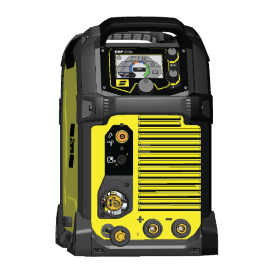
5 OPERATION User connections and controls Front & rear views: Model EMP 255ic & EMP 320ic Knob for current or wire feed speed Positive output [+] selection Knob for voltage selection Polarity changeover cable Main knob for navigation and Display parameter selection Gas outlet for TIG &... -
Page 16: Connection Of Welding And Return Cables
The backside of the door on the bobbin side displays a MIG welding guidance chart for initial selection of welding controls. This is intended as a guide for setting parameters on this equipment. 0463 605 001 - 16 - © ESAB AB 2023... -
Page 17: For Tig Process
The curves below show the maximum voltage and amperage output capabilities of the power source for three common welding process settings. Other settings result in curves that fall between these curves. A= Welding current (AMPS), V = Output voltage 0463 605 001 - 17 - © ESAB AB 2023... -
Page 18: Smaw (Stick) 400
5 OPERATION 5.5.1 SMAW (Stick) 400 V V = Output voltage A = Welding current (Amps) 5.5.2 GMAW (MIG) 400 V V = Output voltage A = Welding current (Amps) 0463 605 001 - 18 - © ESAB AB 2023... -
Page 19: Gtaw (Tig) 400
A different combination of duty cycle and welding current can be selected. Use the graphs below to determine the correct duty cycle for a given welding current. 0463 605 001 - 19 - © ESAB AB 2023... -
Page 20: Removing/Installing Bobbin
To use the 100 mm (4 in.) spool, the plastic bobbin must be removed from the equipment. Tightening the bobbin locking nut for 100 mm (4 in.) spool: Bobbin locking nut Tightening the bobbin locking nut for 200 mm (8 in.), 300 mm (12 in.): 0463 605 001 - 20 - © ESAB AB 2023... -
Page 21: Removing/Installing Wire
If installing aluminum wire, see "Welding with aluminum wire" section. The EMP 255ic or the EMP 320ic will handle bobbin sizes of 100 mm (4 in.), 200 mm (8 in.) and 300 mm (12 in.). See "TECHNICAL DATA" chapter for suitable wire dimensions for each wire type. - Page 22 Do not place or point the torch near the face, hand or body as this may result in injury. NOTE! Make sure the correct wire-feed rollers are selected. NOTE! Remember to use the correct contact tip in the welding torch for the wire diameter used. 0463 605 001 - 22 - © ESAB AB 2023...
-
Page 23: Removing Wire
5.8.1 Removing wire Disconnect the electrical power source from the unit. Open the wire-bobbin side door of the EMP unit. Wire-bobbin Wire-feed assembly Locate the wire-feed assembly and its tension-arm. 0463 605 001 - 23 - © ESAB AB 2023... - Page 24 If wire remains in the torch assembly: Pull the length of old wire out of the torch assembly from either end of the torch assembly. 0463 605 001 - 24 - © ESAB AB 2023...
-
Page 25: Installing Wire
○ Model EMP 255ic uses torch model: PSF 305 (Manual 0458 870 201) ○ Model EMP 320ic uses torch model: PSF 305 (Manual 0458 870 201) 11. To more accurately set and verify the wire-feed tension for correct wire-feed pressure, see "Setting wire-feed pressure"... -
Page 26: Setting Wire-Feed Pressure
Adjusting for correct roller pressure: If you hold the welding torch approximately 50 mm (2 in.) from the piece of wood, the wire should be fed out and bend. 0463 605 001 - 26 - © ESAB AB 2023... -
Page 27: Removing/Installing Wire-Feed Rollers
Failure to comply will render the entire unit useless until this part is replaced. Remove the two wire-feed rollers by removing their retaining screws and washers and then sliding each roller from its shaft (see Figure 7). 0463 605 001 - 27 - © ESAB AB 2023... - Page 28 5 OPERATION Drive gear with woodruff key on motor shaft Drive gear CAUTION! Avoid removing drive gear (see (1) in Figure 6). (Risk loosing drive-shaft woodruff key.) 0463 605 001 - 28 - © ESAB AB 2023...
-
Page 29: Installing Wire-Feed Rollers
When installing the wire-feed rollers avoid (and do not force) installing a roller if either wire guide’s position interferes. Slide the offending wire guide slightly to provide clearance for the roller. The wire-guides are adjusted after the rollers are installed. 0463 605 001 - 29 - © ESAB AB 2023... -
Page 30: Removing/Installing/Adjusting Wire-Guides
"Setting wire-feed pressure" section. Close the door on the wire-bobbin side of the EMP unit. 5.12 Removing/installing/adjusting wire-guides NOTE! The gas does not need to be connected for this procedure. 0463 605 001 - 30 - © ESAB AB 2023... - Page 31 The tensioning arm (see (2) in Figure 5) is spring-loaded. It will pop-up when the tension knob in the previous step is rotated out-of-the-way. 0463 605 001 - 31 - © ESAB AB 2023...
-
Page 32: Output Wire-Guide Removal/Installation
Replace with the new, correct-size tube in the reverse order. Do not tighten its set-screw now (will be done below in "Adjustment"). 0463 605 001 - 32 - © ESAB AB 2023... -
Page 33: Center Wire-Guide Removal/Installation
Lay the wire into the inside groove of the wire-feed rollers. Continue feeding the wire until it projects beyond the Euro-adapter output side by a few centimeters. 0463 605 001 - 33 - © ESAB AB 2023... -
Page 34: Overheating Protection
The trigger switch is pressed, and a low current starts to flow. The welder lifts the electrode from the work piece: the arc strikes, and the current rises automatically to the set value. 0463 605 001 - 34 - © ESAB AB 2023... - Page 35 B = Slope up C = Slope down D = Gas post flow 4-stroke A = Gas pre flow B = Slope up C = Slope down D = Gas post flow 0463 605 001 - 35 - © ESAB AB 2023...
-
Page 36: Control Panel
Manual MIG mode Flux-cored (MIG/MAG) mode MMA mode Lift-TIG mode Settings User manual Dialogue box sMIG mode: Basic Home screen Information Memory Material selection Wire-feed speed selection Material thickness indicator Dialogue box 0463 605 001 - 36 - © ESAB AB 2023... -
Page 37: Smig Mode: Advanced
Manual MIG mode: Advanced Home screen Information Memory Material selection Parameter Wire-feed speed Voltage adjustment Dialogue box Flux cored wire mode: Basic Home screen Information Memory Wire-feed speed Voltage adjustment Dialogue box 0463 605 001 - 37 - © ESAB AB 2023... -
Page 38: Flux Cored Wire Mode: Advanced
Blue changes to orange when output is "hot". 6.10 MMA mode: Advanced Home screen Information Memory Parameter Amperage Power-supply output voltage (Open Circuit Voltage) Arc ON/OFF Dialogue box Blue changes to orange when output is "hot". 0463 605 001 - 38 - © ESAB AB 2023... -
Page 39: Lift-Tig Mode: Basic
Parameter Amperage Dialogue box 6.13 Settings Reset mode Inch/Metric Basic/Advanced Language Information Home screen Dialogue box 6.14 User manual information Maintenance information Wear/Spare parts Operation information Home screen Dialogue box 0463 605 001 - 39 - © ESAB AB 2023... -
Page 40: Icon Reference Guide
Post-flow The time Lift-TIG the shielding gas stays on after the welding arc is stopped Seconds Saving welding programs for a specific application when in the Memory Mode 0463 605 001 - 40 - © ESAB AB 2023... - Page 41 Hot start The Basic Settings increase of amps when striking the electrode to reduce sticking 0463 605 001 - 41 - © ESAB AB 2023...
- Page 42 Stick electrode Unit of Measure choice Upslope, Sloping the Bead profile, current up over a concave period of time at the beginning of the weld cycle Wire diameter Bead profile, convex 0463 605 001 - 42 - © ESAB AB 2023...
-
Page 43: Maintenance
There are no user serviceable parts inside of the power supply side of the EMP unit. Any need for service on the electronics/electrical-power side should be referred to the nearest ESAB service center. Routine maintenance Maintenance schedule during normal conditions:... -
Page 44: Wire-Feeder Assembly Cleaning
Use the following three illustrations for reference during this procedure. Wire from bobbin Output wire-guide (inside of Euro-adapter assy.) Input wire-guide Wire-path through assembly Center wire-guide Output wire-guide thumb Output wire-guide tube Center wire-guide set screw Eurro-adapter assembly Wire-feed rollers 0463 605 001 - 44 - © ESAB AB 2023... - Page 45 7 MAINTENANCE Pressure rollers Wire-feed rollers Tension arm Wire-feed assembly cover 0463 605 001 - 45 - © ESAB AB 2023...
- Page 46 13. Adjust the wire-feed pressure by adjusting the tension on the wire at the wire-feed rollers by turning the tension knob using the procedure in "Setting wire-feed pressure" subsection in "OPERATION" chapter. 14. Close the door on the wire-bobbin side of the EMP unit. 0463 605 001 - 46 - © ESAB AB 2023...
-
Page 47: Emp-Unit Power Side Maintenance
Because of the electro-static sensitive components and exposed circuit boards any maintenance on this side should be done by an authorized ESAB service technician. Torch liner maintenance Refer to MIG torch instruction manual (0458 870 *01) for replacing standard steel torch conduit liner with a Teflon torch conduit liner. -
Page 48: Troubleshooting
Preliminary checks Try these checks and inspections before sending for an authorized service technician. Before attempting to troubleshoot the ESAB Rebel it is recommended to first perform a WELD DATA RESET (navigate to HOME/SETTING/RESET/WELD DATA RESET). A WELD DATA RESET of the system will restore the unit to its default welding condition. -
Page 49: User Interface (Ui) Software Displayed Error Codes
Critical - If occurred at power-up under no-load condition. DC Bus (400 V) fault droop under load, PFC not supplying 400 V to inverter. Output voltage is above VRD levels when VRD switch is active. 0463 605 001 - 49 - © ESAB AB 2023... - Page 50 The image read from the flash is corrupted Failed two attempts of saving user memory to permanent memory in SPI Flash. Failed two attempts of recovering user memory permanent memory from SPI Flash. 0463 605 001 - 50 - © ESAB AB 2023...
-
Page 51: Ordering Spare Parts
Repair and electrical work should be performed by an authorised ESAB service technician. Use only ESAB original spare and wear parts. The EMP 255ic and the EMP 320ic are designed and tested in accordance with international standards IEC-/EN 60974-1, IEC-/EN 60974-5, IEC-/EN 60974-7, IEC-/EN 60974-10, IEC-/EN 60974-12 and IEC-/EN 60974-13. -
Page 52: Diagram
DIAGRAM DIAGRAM Functional Block Diagram Functional Diagram of Power Circuit 0463 605 001 - 52 - © ESAB AB 2023... - Page 53 DIAGRAM 0463 605 001 - 53 - © ESAB AB 2023...
-
Page 54: Ordering Numbers
0700 300 992 EMP 255ic Bobbin Size Ø100–300 mm (4–12 in.) Euro Connector 0700 300 991 EMP 320ic Bobbin Size Ø100–300 mm (4–12 in.) Euro Connector 0463 606 001 EMP 255ic/EMP 320ic Spare Parts manual 0463 605 001 - 54 - © ESAB AB 2023... -
Page 55: Wear Parts
10 0558 102 600 WASHER FLAT M4 LARGE OD 11 0558 102 601 THUMB SCREW M4 X 10 X 8 KNURLED 12 0558 102 602 THUMB SCREW M4 X 10 KNURLED 0463 605 001 - 55 - © ESAB AB 2023... - Page 56 WEAR PARTS Item Ordering no. Description 13 0558 102 603 QUAD WF COVER 14 0558 102 604 THUMB SCREW M5 X 14 KNURLED 0463 605 001 - 56 - © ESAB AB 2023...
-
Page 57: Accessories
0558 102 491 Rebel single cylinder cart Accommodates 1 × 228.6 mm (9 in.) diameter cylinder 0558 102 492 Rebel dual cylinder cart Accommodates 2 × 228.6 mm (9 in.) diameter cylinders 0463 605 001 - 57 - © ESAB AB 2023... -
Page 58: Replacement Parts
0349 312 105 Gas hose, 4.5 m (15 ft.) 0700 006 901 Return welding cable kit, 3 m (10 ft.) 0700 006 900 MMA welding cable kit, 3 m (10 ft.) 0463 605 001 - 58 - © ESAB AB 2023... -
Page 59: Roller & Wire-Guide Selection
TUBE, WIRE GUIDE .052 (1.4) - .062 (1.6), OPTIONAL FOR ALUM PURCHASE * DEFAULT (size included in package) ** ACCESSORY (optional size included with each model 255 or 320 unit) 0463 605 001 - 59 - © ESAB AB 2023... - Page 60 For contact information visit esab.com ESAB AB, Lindholmsallén 9, Box 8004, 402 77 Gothenburg, Sweden, Phone +46 (0) 31 50 90 00 manuals.esab.com...
Need help?
Do you have a question about the EMP 320ic and is the answer not in the manual?
Questions and answers