
Related Manuals for ESAB EMP 285ic 1ph


Summary of Contents for ESAB EMP 285ic 1ph
- Page 1 INSTRUCTION MANUAL EMP 285ic 1ph & EMP 285ic 3ph Valid for: serial nos. 745-xxx-xxxx, 747-xxx-xxxx Rights reserved to alter specifications without notice. PART # 0463 618 001 © ESAB AB 2018...
- Page 2 (Intentionally Blank)
- Page 3 BE SURE THIS INFORMATION REACHES ALL OPERATORS OF THIS EQUIPMENT. EXTRA COPIES ARE AVAILABLE THROUGH THE ESAB SUPPLIER OR FROM THE ESAB WEB SITE: WWW.ESAB.COM. CAUTION These INSTRUCTIONS are for experienced operators. If you are not fully familiar with the...
- Page 4 (Intentionally Blank)
-
Page 5: Table Of Contents
2.1.14 USER RESPONSIBILITY..................2-9 SECTION 3 INTRODUCTION KEY FEATURES ....................3-1 EQUIPMENT ......................3-1 3.2.1 EMP 285ic 1ph ....................3-1 3.2.2 EMP 285ic 3ph: ....................3-2 OVERHEATING PROTECTION ................3-2 SECTION 4 TECHNICAL SPECIFICATIONS EMP 285IC (1PH) SPECIFICATIONS ..............4-1 EMP 285IC (3PH) SPECIFICATIONS .............. - Page 6 SECTION TABLE OF CONTENTS Paragraph Page 5.2.1 User’s Responsibility ..................5-3 5.2.2 Assessment of Area ..................5-3 LIFTING INSTRUCTIONS ..................5-4 MAIN SUPPLY ..................... 5-5 RECOMMENDED ELECTRICAL-SUPPLY SPECIFICATIONS........5-6 SUPPLY FROM POWER GENERATORS ..............5-7 SECTION 6 OPERATION UNIT’S CONNECTIONS AND CONTROLS .............. 6-2 CONNECTION OF WELDING AND RETURN CABLES ..........
- Page 7 SECTION TABLE OF CONTENTS Paragraph Page 6.12.3 ADJUSTING WIRE GUIDES ................6-32 SECTION 7 CONTROL PANEL HOW TO NAVIGATE .................... 7-1 MAIN MENU ....................... 7-1 SMIG MODE: BASIC .................... 7-2 SMIG MODE: ADVANCED ................... 7-2 MANUAL MIG MODE: BASIC................7-3 MANUAL MIG MODE: ADVANCED ..............
- Page 8 SECTION TABLE OF CONTENTS Paragraph Page (Intentionally Blank)
- Page 9 SECTION LIST OF FIGURES Figure Page Figure 2-1. Danger and Warning Symbols ................2-1 Figure 5-1. Minimum Safe Clearances ................. 5-1 Figure 5-2. Lifting Illustrated ....................5-4 Figure 5-3. Sloping Ground ....................5-4 Figure 5-4. Rating plate (1) with supply connection data ............. 5-6 Figure 6-1.
- Page 10 SECTION LIST OF FIGURES Figure Page Figure 6-28. Feed Roller Removal and Installation ............. 6-26 Figure 6-29. Wire-Feed Rollers Offered in Multiple Sizes ........... 6-27 Figure 6-30. Location of Wire-Guides and Their Set Screws ..........6-29 Figure 6-31. Wire Guides ....................6-30 Figure 6-32.
- Page 11 SECTION LIST OF TABLES Table Page Table 4-1. Specifications for EMP 285ic 1ph ................ 4-1 Table 4-2. Specifications for EMP 285ic 3ph ................ 4-4 Table 5-1. Recommended Electrical-Supply Specifications: 1 ph, 50/60 Hz ......5-6 Table 5-2. Recommended Electrical-Supply Specifications 3 ph, 50/60 Hz ......5-7 Table 8-1.
- Page 12 (Intentionally Blank)
- Page 13 APPENDIX TABLE OF CONTENTS Paragraph Page DIAGRAMS FUNCTIONAL BLOCK DIAGRAM 3 PH ..............10-1 FUNCTIONAL BLOCK DIAGRAM 1 PH ..............10-2 Lift-TIG Welding 2-STROKE AND 4-STROKE WELDING PROCESS ILLUSTRATED ......B-1 Roller & Wire-Guide Selection ROLLER SELECTION ..................... C-1 WIRE-GUIDE SELECTION ..................C-1 GLOSSARY...
- Page 14 (Intentionally Blank)
-
Page 15: Section 1 Welcome To Esab
DESCRIPTION The ESAB EMP 285ic 1ph (230V or 120V) and the EMP 285ic 3ph (575V or 460V) are 50/60 Hz, constant current welding machines capable of performing SMAW (STICK), and GTAW (LIFT TIG) welding processes and constant voltage welding capable of performing GMAW (MIG) welding processes. - Page 16 (Intentionally Blank)
-
Page 17: Section 2 Safety
Safety Precautions could result in injury or death. 2.1.2 SAFETY PRECAUTIONS Users of ESAB equipment have the ultimate responsibility for ensuring that anyone who works on or near the equipment observes all the relevant safety precautions. Safety precautions must... - Page 18 SAFETY meet the requirements that apply to this type of equipment. The following recommendations should be observed in addition to the standard regulations that apply to the workplace. All work must be carried out by trained personnel well-acquainted with the operation of the equipment.
-
Page 19: Fires And Explosions
SAFETY • Hot sparks or metal can lodge in rolled up sleeves, trouser cuffs, or pockets. Sleeves and collars should be kept buttoned (closed) and open pockets should be eliminated from the front of the clothing. • Protect other personnel from arc rays and hot sparks with a suitable non-flammable partition or curtains. -
Page 20: Electrical Shock
SAFETY 8. After completing work, inspect the work area to make sure there are no hot sparks or hot metal that could cause a fire later. Use fire watchers when necessary. 2.1.4 ELECTRICAL SHOCK ELECTRIC SHOCK can kill. ELECTRIC SHOCK - Can kill Therefore: 1. -
Page 21: Fumes And Gases
SAFETY Therefore: 1. Welders with medical pacemakers fitted should consult their doctor before welding. EMF may interfere with some pacemakers. 2. Exposure to EMF may have other health effects which are unknown. 3. Welders should use the following procedures to minimize exposure to EMF: a. -
Page 22: Cylinder Handling
SAFETY exposures. Install appropriate ventilation controls or cease surrounding activity if fumes become an exposure issue outside of the immediate work area 5. Do not operate near degreasing and spraying operations. The heat or arc can react with chlorinated hydrocarbon vapors or liquids to form phosgene, a highly toxic gas, and other irritant gases. -
Page 23: Moving Parts
SAFETY 5. Use the proper gas for the process and use the proper pressure reducing regulator designed to operate from the compressed gas cylinder. Do not use adapters. Maintain hoses and fittings in good condition. Follow the manufacturer's operating instructions for mounting a regulator to a compressed gas cylinder. 6. -
Page 24: Falling Equipment
SAFETY 3. Maintain cables, earthing wire, connections, power cord and power supply in safe working order. Do not operate faulty equipment in a faulty condition. 4. Do not abuse any equipment or accessories. Keep equipment away from heat sources such as furnaces, wet conditions such as water puddles, oil or grease, corrosive atmospheres and inclement weather. -
Page 25: User Responsibility
This equipment or any of its parts should not be altered from standard specification without prior written approval of ESAB. The user of this equipment shall have the sole responsibility for any malfunction which results from improper use or unauthorized modification from standard specification, faulty maintenance, damage or improper repair by anyone other than appropriately qualified persons approved by ESAB. - Page 26 SAFETY • location of emergency stops and safety features • its function • relevant safety precautions • welding and cutting methods or other applicable operations of the equipment 2. THE OPERATOR MUST ENSURE THAT: • no unauthorized person is within the working area of the equipment when it is started up •...
- Page 27 SAFETY (Intentionally Blank) 2-11...
-
Page 28: Section 3 Introduction
INTRODUCTION INTRODUCTION SECTION 3 The ESAB, EMP product family is a new generation of multi-process (MIG/Stick/TIG) welding power sources. All Rebel power sources are designed to match the needs of the user. They are tough, durable, and portable, providing excellent arc performance across a variety of welding applications. -
Page 29: Emp 285Ic 3Ph
• Ground clamp, 10 ft. (3 m), 300 A • Victor® Flow Meter with 6 ft (2 m) gas hose • ESAB OK AristoRod™ premium solid wire 0.035 in. (0.9 mm) 11# spool • ESAB Atom Arc Acclaim 1/8 in. premium stick electrodes 1# sample pack •... -
Page 30: Section 4 Technical Specifications
• Generator Requirements at the Maximum Output Cycle. • Due to large variations in performance and specifications of different brands and types of generators, ESAB cannot guarantee full welding output power or duty cycle on every brand or type of generator. ESAB recommends that when selecting a generator, that the power source/generator combination be adequately tested to ensure the combination performs to the user’s expectations without notice. - Page 31 TECHNICAL SPECIFICATIONS SPECIFICATION 230 V ±10%, 1 ph, 50/60 Hz 120 V ±10%, 1 ph, 50/60 Hz 60% duty cycle* 220A (V = 25V) Breaker 15A: 90A (V 18.5V) Breaker 20A: 110A (V 19.5V) 40% duty cycle* 285A (V = 28V) Breaker 15A: 100A (V 19V) Setting range (DC)
- Page 32 TECHNICAL SPECIFICATIONS SPECIFICATION 230 V ±10%, 1 ph, 50/60 Hz 120 V ±10%, 1 ph, 50/60 Hz 4–12 in. (100–300 mm) 4–12 in. (100–300 mm) Bobbin size Dimensions l × w × h 686 × 292 × 495 mm (27.0 × 686 ×...
-
Page 33: Emp 285Ic (3Ph) Specifications
TECHNICAL SPECIFICATIONS EMP 285ic (3ph) SPECIFICATIONS Table 4-2. Specifications for EMP 285ic 3ph SPECIFICATION 575 V, 3 ph 50/60 Hz 460 V, 3 ph 50/60 Hz PRIMARY CURRENT 15.0A per phase Imax. GMAW - MIG 18.0A per phase 10.5A per phase Imax. - Page 34 TECHNICAL SPECIFICATIONS SPECIFICATION 575 V, 3 ph 50/60 Hz 460 V, 3 ph 50/60 Hz Mild steel solid wire 0.030-0.052 in. 0.030-0.052 in. Stainless steel solid wire 0.030-0.052 in. 0.030-0.052 in. Flux-cored wire 0.030-0.062 in. 0.030-0.062 in. Aluminum 0.030-3/64 in. 0.030-3/64 in.
-
Page 35: Section 5 Installation
INSTALLATION INSTALLATION SECTION 5 The installation must be carried out by a professional. CAUTION This product is intended for industrial use. In a domestic environment this product may cause radio interference. It is the user’s responsibility to take adequate precautions. LOCATION Position the power source so that its cooling air inlets and outlets are not obstructed. -
Page 36: High Frequency Interference
INSTALLATION HIGH FREQUENCY INTERFERENCE WARNING The high frequency section of this machine has an output like a radio transmitter. The machine should NOT be used near blasting operations due to the danger of premature firing. WARNING Operation close to computer installations may cause computer malfunction. WARNING HIGH FREQUENCY FIELDS CAN BE DANGEROUS TO HEALTH. -
Page 37: User's Responsibility
INSTALLATION WARNING The importance of correct installation of high frequency welding equipment cannot be overemphasized. Interference due to high frequency initiated or stabilized arc is almost invariably traced to improper installation. A duly authorized person such as a properly licensed electrician should perform the installation to avoid injury, death, or any equipment damage. -
Page 38: Lifting Instructions
INSTALLATION • Direct Radiation: Radiation from the machine can occur if the case is metal and is not properly grounded. It can occur through apertures such as open access panels. The shielding of the high frequency unit in the Power Source will prevent direct radiation if the equipment is properly grounded. -
Page 39: Main Supply
INSTALLATION MAIN SUPPLY NOTE Main supply requirements: This equipment complies with IEC 61000-3-12 provided that the short-circuit power is greater than or equal to Sscmin at the interface point between the user’s supply and the public system. It is the responsibility of the installer or user of the equipment to ensure, by consultation with the distribution network operator if necessary, that the equipment is connected only to a... -
Page 40: Recommended Electrical-Supply Specifications
INSTALLATION Figure 5-4. Rating plate (1) with supply connection data RECOMMENDED ELECTRICAL-SUPPLY SPECIFICATIONS WARNING An electrical shock or fire hazard is probable if the following electrical service guide recommendations are not followed. These recommendations are for a dedicated branch circuit sized for the rated output and duty cycle of the welding power source. -
Page 41: Supply From Power Generators
INSTALLATION Table 5-2. Recommended Electrical-Supply Specifications 3 ph, 50/60 Hz Specification Value Supply ± 10% 460 V or 575 V Input current at maximum output 18 A Maximum recommended fuse* or circuit breaker rating 16 A *Time delay fuse Minimum recommended cord size 2.5 mm2 (13 AWG) Maximum recommended extension cord length 15 m (50ft) -
Page 42: Section 6 Operation
OPERATION OPERATION SECTION 6 General safety regulations for handling the equipment can be found in the "SAFETY PRECAUTIONS" section of this manual. Read it through before you start using the equipment! NOTE When moving the equipment use intended handle. Never pull the cables. WARNING! Rotating parts can cause injury, take great care. -
Page 43: Unit's Connections And Controls
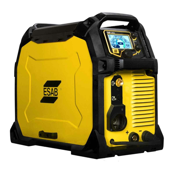
OPERATION UNIT’S CONNECTIONS AND CONTROLS Figure 6-1. Front & Rear Views: Model EMP 285ic 1. Knob for current or wire feed speed selection 8. Positive output ( + ) 2. Knob for voltage selection 9. Polarity changeover cable 3. Main knob for menu navigation 10. -
Page 44: Connection Of Welding And Return Cables
OPERATION 1. (U) UPPER CONTROL KNOB: a. SET CURRENT OUTPUT VALUE b. SET WIRE FEED SPEED 2. (L) LOWER CONTROL KNOB: a. MIG VOLTAGE SELECTION b. SMIG VOLTAGE TRIM c. MMA MODE: ARC ON/OFF 3. (M) MENU NAVIGATION: (PUSH TO SELECT) Figure 6-2. -
Page 45: For Tig Process
OPERATION 6.2.2 FOR TIG PROCESS For TIG process (requires optional TIG accessories), connect the TIG torch power cable to the negative [-] terminal (7), see illustration. Connect the gas inlet nut on the TIG torch to the gas outlet connector (4) located on the front of the machine. Connect the gas inlet nut (12), on rear panel, to a regulated shielding gas supply. -
Page 46: Volt-Ampere Curves
OPERATION VOLT-AMPERE CURVES The curves below show the maximum voltage and amperage output capabilities of the power source for three common welding process settings. Other settings result in curves that fall between these curves. A=Welding current (AMPS), V=Output voltage 6.5.1 1ph VOLT-AMPERE CURVES 6.5.1.1 SMAW (Stick) 120 V, 1ph... -
Page 47: Gmaw (Mig) 120 V, 1Ph
OPERATION 6.5.1.3 GMAW (MIG) 120 V, 1ph Figure 6-5. GMAW (MIG), 120 V, 1 ph 6.5.1.4 GMAW (MIG) 230 V, 1ph Figure 6-6. GMAW (MIG) 230 V, 1ph... -
Page 48: Gtaw (Tig) 120 V, 1Ph
OPERATION 6.5.1.5 GTAW (TIG) 120 V, 1ph Figure 6-7. GTAW (TIG) 120 V, 1ph 6.5.1.6 GTAW (TIG) 230 V, 1ph Figure 6-8. GTAW (TIG) 230 V, 1ph... -
Page 49: 3Ph Volt-Ampere Curves
OPERATION 6.5.2 3ph VOLT-AMPERE CURVES 6.5.2.1 SMAW (Stick) 460 V, 3ph / SMAW (Stick) 575 V, 3ph Figure 6-9. SMAW (Stick) 460 V, 3ph / SMAW (Stick) 575 V, 3ph 6.5.2.2 GMAW (MIG) 460 V, 3ph / GMAW (MIG) 575 V, 3ph GMAW(MIG) MIG MAX MIG MIN... -
Page 50: Gtaw (Tig) 460 V, 3Ph / Gtaw (Tig) 575 V, 3Ph
OPERATION 6.5.2.3 GTAW (TIG) 460 V, 3ph / GTAW (TIG) 575 V, 3ph Figure 6-11 GTAW (TIG) 460 V, 3ph / GTAW (TIG) 575 V, 3ph... -
Page 51: Duty Cycle
OPERATION DUTY CYCLE A self-resetting thermostat will protect the power source if the duty cycle is exceeded. Example: If the power source operates at a 40% duty cycle, it will provide the rated amperage for a maximum of 4 minutes out of every 10-minute period. The remaining time, 6 minutes, the power source must be allowed to cool down. - Page 52 OPERATION Duty cycle on 120V AC MIG@20A MIG@15A 90 100 110 120 130 140 Welding Current (Amps) Figure 6-14. Plotting Duty Cycle for 120 V, 1ph AC Duty cycle on 230V AC 100 110 120 130 140 150 160 170 180 190 200 210 220 230 240 250 260 270 280 290 300 Welding Current (Amps Figure 6-15.
- Page 53 OPERATION Figure 6-16 Plotting Duty Cycle for 460 V or 575 V, 3ph AC 6-12...
-
Page 54: Removing/Installing Bobbin
OPERATION REMOVING/INSTALLING BOBBIN NOTE The gas need not be connected for this procedure. Power should be turned off for this procedure. The spring sets the “braking value” working against the wire-feed motor and the pull of the roller-feed wheels. Tighten the bolt “A” (see Figure 6-17 or Figure 6-18) hand tight. 1. - Page 55 OPERATION NOTE The larger Bobbin may come in the wire form shown in the Figure or may be molded plastic form. Either mounts the same way as shown. Figure 6-18. Tightening the Bobbin Locking Nut (A) for 200 mm (8 in.), 300 mm (12 in.) 6-14...
-
Page 56: Removing/Installing Wire
OPERATION REMOVING/INSTALLING WIRE NOTE If installing aluminum wire, see Section 6.9. The EMP 285ic will handle bobbin sizes of 100 mm (4 in.), 200 mm (8 in.) and 300 mm (12 in.). See TECHNICAL SPECIFICATIONS section for suitable wire dimensions for each wire type. WIRE BOBBIN GAS VALVES WIRE-FEED ASSEMBLY... -
Page 57: Removing Wire
OPERATION 6.8.1 REMOVING WIRE 1. Disconnect the electrical power source from the unit. 2. Open the wire-bobbin side cover of the EMP unit. WIRE BOBBIN QUAD WIRE-FEED ASSEMBLY Figure 6-20. Wire-Bobbin Side Exposed View 3. On the Wire-Feed Assembly release the tensioning arm by pulling it up out of its detent and rotating it toward you (see (1) in Figure 6-21). - Page 58 OPERATION TENSIONING ARM WIRE TORCH OUTPUT WIRE-FEED TENSION KNOB CENTER WIRE-FEED GUIDE INPUT WIRE-FEED GUIDE Figure 6-21. Wire-Feed Mechanism 4. IF WIRE REMAINS IN THE TORCH ASSEMBLY: Near the input end of the wire-feed guide on the wire-feed assembly (see Figure 6-21) cut the wire while holding the bobbin-end (so the wire does not unravel from the bobbin after cutting it loose).
-
Page 59: Installling Wire
OPERATION TORCH CONNECTOR HOLDING KNOB Figure 6-22. Holding Knob for Torch Adapter 6. Pull the remaining length of the wire through the wire-feed assembly and, with the torch, set the torch assembly aside (with the loose wire still installed in the torch). The old wire should now be completely removed from the wire-feed assembly. - Page 60 Refer to the relevant Torch manual for length of wire-protrusion at tip end. • Model EMP 285ic 1ph uses torch model: Spray Master Velocity 250V • Model EMP 285ic 3ph uses torch model: Spray Master Velocity 350V 11.
-
Page 61: Welding With Aluminum Wire
• Torch Teflon Conduit Liner (PTFE liner), 3 m (10 ft.): See PARTS section (Wire Liner Table) in the ESAB Torch Instruction Manual (see NOTE above). • Teflon coated Output Wire-Guide Tube (select size to match wire from Table in Appendix C). -
Page 62: Setting Wire-Feed Pressure
OPERATION 6.10 SETTING WIRE-FEED PRESSURE NOTE This procedure requires the unit be powered ON. The gas does not need to be connected for this procedure. 1. Turn power to the unit ON. 2. Start by making sure that the wire moves smoothly through the wire guide. CAUTION It is important that the feed-pressure is not too high or too low. - Page 63 OPERATION 5. ADJUSTING FOR CORRECT ROLLER PRESSURE: If you hold the welding torch approximately 2 in. (50 mm) from the piece of wood, the wire should be fed out and bend (Figure 6-24). HARD WOOD SURFACE 2 inches Figure 6-24. Checking for Proper Feed-Roller Pressure 6-22...
-
Page 64: Removing/Installing Wire-Feed Rollers
OPERATION 6.11 REMOVING/INSTALLING WIRE-FEED ROLLERS WARNING POWER SHOULD BE TURNED OFF FOR THIS PROCEDURE. NOTE Gas does not need to be connected for this procedure. Different-size pairs of dual-groove feed-rollers are supplied as standard (Listed in Appendix C as “DEFAULT” and as “ACCESSORY”). Change the feed rollers to match the wire size/type on the wire bobbin. -
Page 65: Removing Wire-Feed Rollers
OPERATION 6.11.1 REMOVING WIRE-FEED ROLLERS 1. If new rollers are being installed select the correct size and type (Steel or aluminum) for wire being installed (See Appendix C). 2. Disconnect the electrical power source from the unit. 3. Open the cover on the wire-bobbin side of the EMP unit. 4. - Page 66 OPERATION CAUTION When removing the drive roller (roller located on left side) be careful NOT to remove the drive gear with it. Doing so risks losing the small Woodruff key on the motor shaft. Failure to comply will render the entire unit useless until this part is replaced (see Figure 6 20). 6.
-
Page 67: Installing Wire-Feed Rollers
OPERATION Figure 6-28. Feed Roller Removal and Installation 6.11.2 INSTALLING WIRE-FEED ROLLERS CAUTION When installing the Wire-Feed Rollers avoid (and do not force) installing a roller if either wire guide’s position interferes. Slide the offending wire guide slightly to provide clearance for the roller. - Page 68 OPERATION LABEL ON ROLLER-SIDE MATCHES WITH THE GOOVE ON THE OPPOSITE- SIDE OF THE ROLLER. Figure 6-29. Wire-Feed Rollers Offered in Multiple Sizes 2. Tighten the Drive-Roller retaining screw by turning it in the clockwise direction. Hand-tight is sufficient. 3. The wire must be installed through the wire-feed assembly (See Section 6.8.2 INSTALLING WIRE).
-
Page 69: Removing/Installing/Adjusting Wire-Feed Guides
OPERATION 6.12 REMOVING/INSTALLING/ADJUSTING WIRE-FEED GUIDES NOTE The gas does not need to be connected for this procedure. NOTE The OUTPUT WIRE-GUIDE TUBE must be selected to match the size that corresponds with the wire size and type (steel or aluminum) selected for use. There are three wire-feed guide tubes: Input Wire-Guide Tube, Center Wire-Guide Tube and Output Wire-Guide Tube. - Page 70 OPERATION CENTER WIRE-GUIDE OUTPUT WIRE-GUIDE TUBE INPUT WIRE-GUIDE WIRE WIRE-PATH FROM THROUGH ASSEMBLY BOBBIN WIRE-FEED ROLLERS OUTPUT WIRE-GUIDE THUMB SCREW CENTER WIRE-GUIDE SET SCREW Figure 6-30. Location of Wire-Guides and Their Set Screws 1. Select and obtain the correct replacement wire guides (See Appendix C). NOTE Since this is based on the size and type (steel or aluminum) wire selected, it is assumed that the wire is...
- Page 71 OPERATION 4 SIZES FOR STEEL WIRE 3 SIZES FOR ALUMINUM WIRE (SELECT FROM TABLE IN APPENDIX C) ONE SIZE FITS ALL CENTER WIRE- GUIDE OUTPUT WIRE- GUIDE Figure 6-31. Wire Guides 2. Disconnect the electrical power source from the unit. 3.
- Page 72 OPERATION TENSIONING ARM WIRE TORCH OUTPUT WIRE-FEED GUIDE TENSION KNOB CENTER WIRE-FEED GUIDE INPUT WIRE-FEED GUIDE Figure 6-32. Wire-Feed Mechanism 5. To remove the wire from the EMP unit cut the wire just before entry into the wire- feed assembly. Be sure to hold the bobbin-end of the wire before cutting to restrain the wire from unravelling from its spooling on the bobbin.
-
Page 73: Output Wire-Guide Removal/Installation
OPERATION 6.12.1 OUTPUT WIRE-GUIDE REMOVAL/INSTALLATION 1. Loosen the Output Wire-Guide thumb screw (see Figure 6-30). 2. Remove the Output Wire-Guide Tube out-through and out-of the CSA adapter Assembly. 3. Replace with the new, correct-size tube in the reverse order. Do NOT tighten its set- screw now (will be done below in ADJUSTING WIRE GUIDES). - Page 74 OPERATION ADJUST FOR, AND VERIFY, APPROXIMATELY 1 MM CLEARANCE BETWEEN ROLLER AND GUIDE TUBES Figure 6-33. Verify Clearance of Both Guide Tubes 3. Access the bitter-end of the wire on the bobbin and cut off the length from the bitter end to have a clean, straight, bitter-end. This is needed to allow a low- resistance-travel re-install of the wire along the length of the torch cable to the torch tip.
- Page 75 OPERATION 9. Adjust the wire-feed pressure by adjusting the tension on the wire at the Wire-Feed Rollers by using the procedure SETTING THE WIRE-FEED PRESSURE (see Section 6.10) for a more accurate adjustment of this tension knob. 10. Close the cover on the wire-bobbin side of the EMP unit. 6-34...
-
Page 76: Section 7 Control Panel
CONTROL PANEL CONTROL PANEL SECTION 7 NOTE After power-on has completed the main menu appears on the control panel. HOW TO NAVIGATE 1. (U) UPPER CONTROL KNOB: a. SET CURRENT OUTPUT VALUE b. SET WIRE FEED SPEED 2. (L) LOWER CONTROL KNOB: a. -
Page 77: Smig Mode: Basic
CONTROL PANEL SMIG MODE: BASIC 1. HOME SCREEN 2. INFORMATION 0.039 in 3. MEMORY 4. MATERIAL SELECTION 5. WIRE-FEED SPEED SELECTION (U) 6. MATERIAL THICKNESS INDICATOR 7. DIALOGUE BOX SMIG MODE: ADVANCED 1. HOME SCREEN 2. INFORMATION 0.047 in 3. MEMORY 4. -
Page 78: Manual Mig Mode: Basic
CONTROL PANEL MANUAL MIG MODE: BASIC 1. HOME SCREEN 2. INFORMATION 3. MEMORY 4. MATERIAL SELECTION 5. PARAMETER 6. WIRE-FEED SPEED (U) 7. VOLTAGE ADJUSTMENT (L) 8. DIALOGUE BOX MANUAL MIG MODE: ADVANCED 1. HOME SCREEN 2. INFORMATION 3. MEMORY 4. -
Page 79: Flux Cored Wire Mode: Basic
CONTROL PANEL FLUX CORED WIRE MODE: BASIC 1. HOME SCREEN 2. INFORMATION 3. MEMORY 4. WIRE-FEED SPEED (U) 5. VOLTAGE ADJUSTMENT (L) 6. DIALOGUE BOX FLUX CORED WIRE MODE: ADVANCED 1. HOME SCREEN 2. INFORMATION 3. MEMORY 4. PARAMETER 5. WIRE-FEED SPEED (U) 6. -
Page 80: Mma Mode: Basic
CONTROL PANEL MMA MODE: BASIC 1. HOME SCREEN 2. INFORMATION 3. MEMORY 4. AMPERAGE ADJUSTMENT (U) 5. POWER-SUPPLY OUTPUT VOLTAGE (OPEN CIRCUIT VOLTAGE OR ARC) 6. DIALOGUE BOX 7. ARC ON/OFF (L) BLUE CHANGES TO ORANGE WHEN OUTPUT IS “HOT” 7.10 MMA MODE: ADVANCED 1. -
Page 81: Lift-Tig Mode: Basic
CONTROL PANEL 7.11 LIFT-TIG MODE: BASIC 1. HOME SCREEN 2. INFORMATION 3. MEMORY 4. AMPERAGE (U) 5. DIALOGUE BOX 7.12 LIFT-TIG MODE: ADVANCED 1. Home screen 1. HOME SCREEN 2. Information 2. INFORMATION 3. Memory 3. MEMORY 4. Parameter 4. PARAMETER 5. -
Page 82: Settings
CONTROL PANEL 7.13 SETTINGS 1. RESET MODES 2. INCH/METRIC 3. BASIC/ADVANCED 4. LANGUAGE 5. INFORMATION 6. HOME SCREEN 7. DIALOGUE BOX 7.14 USER MANUAL INFORMATION 1. MAINTENANCE INFORMATION 2. WEAR/SPARE PARTS 3. OPERATION INFORMATION 4. HOME SCREEN 5. DIALOGUE BOX... -
Page 83: Icon Reference Guide
CONTROL PANEL 7.15 Icon reference guide NOTE: SCT – Short Circuit Termination is a method of automatic burn back at the end of the weld to electrically cut the wire by pulsing high current in a controlled process. The result is a nice clean wire end with no balling or sticking to the weld pool or tip. - Page 84 CONTROL PANEL ICON MEANING ICON MEANING Parameters Flux cored Parameters Manual MIG STICK Percent Pre-flow The time the shielding gas stays on before Smart MIG the welding arc is started Post-flow The time the shielding gas stays Lift-TIG on after the welding arc is stopped Saving welding...
- Page 85 CONTROL PANEL ICON MEANING ICON MEANING Settings Foot control Volts 2T, Trigger On/OFF 4T, Trigger User manual on Hold/Lock main menu Plate thickness at Amps sMIG mode Arc force On stick welding- Trim bar Changing increasing amps the weld bead profile when the arc from flat to convex or length is...
- Page 86 CONTROL PANEL ICON MEANING ICON MEANING Inductance The addition of inductance into the arc characteristics ENGLISH Language selection to stabilize the arc and reduce spatter when in the short circuit process Memory Ability to save Stick electrode welding choice programs for a specific application Upslope...
-
Page 87: Section 8 Maintenance
Perform maintenance more often during severe dusty conditions. NOTE There are no user serviceable parts inside of the power supply side of the EMP unit. Any need for service on the electronics/electrical-power side should be referred to the nearest ESAB service center. -
Page 88: Routine Maintenance
MAINTENANCE ROUTINE MAINTENANCE Table 8-1. Maintenance Schedule During Normal Conditions Interval Area to maintain Every 3 months Clean or replace Clean weld Check or replace weld cables. unreadable labels. terminals. Every 6 months Clean inside equipment. WIRE-FEEDER ASSEMBLY MAINTENANCE General good practice is to perform this procedure each time a Wire Bobbin is replaced. 8.2.1 WIRE-FEEDER ASSEMBLY CLEANING WARNING... - Page 89 MAINTENANCE TENSION ARM QUAD WIRE-FEED ASSEMBLY COVER Figure 8-1. Tension Arm & Wire-Feed Cover on Wire-Feed Assembly 1. Disconnect the electrical power source from the unit. 2. Open the cover on the wire-bobbin side of the EMP unit. 3. Release the tension from the Pressure Rollers by turning the Tension Knob on the Tension Arm counter-clockwise enough to pull it first up (out of its detent slot) and then toward you (see 1 in Figure 6-32).
- Page 90 MAINTENANCE CAUTION Avoid removing the drive gear behind the left wire-feed roller. Doing so risks losing the Woodruff key on the motor shaft. Losing this key renders the unit useless until the key is replaced. 6. Remove the Wire-Feed Rollers per Section 6.11.1 REMOVING WIRE-FEED ROLLERS. 7.
-
Page 91: Emp-Unit Power-Side Maintenance
Refer to MIG torch instruction manual for replacing standard steel torch conduit liner with a Teflon torch conduit liner. • Model EMP 285ic 1ph uses torch model: Spray Master Velocity 250V • Model EMP 285ic 3ph uses torch model: Spray Master Velocity 350V 8.4.1... -
Page 92: Section 9 Troubleshooting
PRELIMINARY CHECKS Try these checks and inspections before sending for an authorized service technician. Before attempting to troubleshoot the ESAB Rebel it is recommended to first perform a WELD DATA RESET (navigate to HOME/SETTING/RESET/WELD DATA RESET). A WELD DATA RESET of the system will restore the unit to its default welding condition. - Page 93 TROUBLESHOOTING Type of fault Corrective action MIG (GMAW/FCAW) • Make sure the MIG torch is connected to the correct welding problems polarity. Refer to the electrode wire manufacturer for the correct polarity. • Replace contact tip if it has arc marks in the bore causing excessive drag on the wire.
-
Page 94: User Interface (Ui) Software-Displayed Error Codes
TROUBLESHOOTING Type of fault Corrective action Overheating protection trips • Make sure that you are not exceeding the recommended frequently. duty cycle for the weld current you are using. See section "Duty cycle" in the OPERATION chapter. • Make sure the air inlets or outlets are not clogged. •... -
Page 95: Section 10 Ordering Spare Parts
Repair work should be done by an authorized ESAB service technician. Use only ESAB parts. The EMP 285ic 1ph and the EMP 285ic 3ph is designed and tested in accordance with international standards IEC-/EN 60974-1, IEC-/EN 60974-5, IEC-/EN 60974-7, IEC-/EN 60974- 10, IEC-/EN 60974-12, and IEC-/EN 60974-13. - Page 96 SPARE PARTS Table 10-1. Unit Part Numbers Part # Description Note 0558102554 EMP 285ic 1ph Bobbin Size 100–300 mm (4–12 in), bayonet 0558102556 EMP 285ic 3ph Bobbin Size 100–300 mm (4–12 in.), bayonet Spare Parts List 463619001 10-2...
-
Page 97: Wear Parts
SPARE PARTS 10.2 WEAR PARTS Certain mechanical parts on the wire-feed assembly are subject to more frequent use hence may wear more frequently. These are exhibited here. Figure 10-1. Wire-Feed Assembly, Wear-Parts Table 10-2. Reference for Figure 10-2 Wire-Feed Assembly, Wear-Parts PART # DESCRIPTION 0558102591... -
Page 98: Accessories
SPARE PARTS 10.3 ACCESSORIES Table 10-3. Accessories Part # Description 1023-1277 MIG Torch: Spray Master Velocity 250V, 15 ft (4.5 m) 1036-1756 MIG Torch: Spray Master Velocity 350V, 15 ft (4.5 m) 0558102493 TIG Torch: TXH™ 201, 4 m (12 ft.) TIG torch c/w 8-pin plug W4014450 Foot control: Contactor on/off and current... -
Page 99: Replacements Parts
SPARE PARTS 10.4 REPLACEMENTS PARTS Table 10-4. Replacement Part # Part # Description 0781-2743 Victor® Flow Meter with 10 ft (3 m) gas hose WS200G10 Tweco Ground Clamp w/Lead, 10 ft. (3m), 50 mm Dinse WS200E13 Electrode Holder 200A and Lead Assembly, 13 ft. (4 m), 50 mm Dinse W4014000 Power adapter cable 230 V to 120 V, 15 A 354TA8... - Page 100 DIAGRAMS DIAGRAMS A.1 Functional Block Diagram 3 ph DESCRIPTION Main Power Switch EMI Filter Board Primary Rectifier on Power Board Primary Inverter on Power Board Main Transformer Ferrite Cores Output Diode Assembly Current Sensor Output Inductor 10 Internal Power Supply Board 11 Control Board 12 User Interface (UI) 13 Wire Feeder...
- Page 101 DIAGRAMS A.2 Functional Block Diagram 1 ph DESCRIPTION Main Power Switch with thermal breaker Primary Rectifier on Power Board Boost PFC Primary Inverter on Power Board Main Transformer Ferrite Rings Output Diode Assembly Current Sensor Output Inductor 10 Internal Power Supply on Power Board 11 Control Board 12 User Interface (UI) 13 Wire Feeder...
- Page 102 Lift-TIG Welding 2-Stroke and 4-Stroke Welding Process Illustrated The trigger is used and some current flows already when lifting away the electrode to strike it. Striking the arc with the LiftArc function: Step 1: the electrode is touched on to the work piece. Step 2: the trigger switch is pressed, and a low current starts to flow.
- Page 103 2 STROKE 2 STROKE Gas pre-flow Slope Slope down Gas post- flow 4 STROKE 4 STROKE Torch lifted here Gas pre-flow Slope Slope down Gas post- flow...
- Page 104 Roller & Wire-Guide Selection Roller Selection ITEM PART # DESCRIPTION COMMENT FEED ROLLERS FOR ALL WIRES EXCEPT ALUMINUM 21155 ROLLER, .024 (.6) - .030 (.8), V-SOLID OPTIONAL FOR PURCHASE 21156 ROLLER, .035 (0.9) - .045 (1.2), V-SOLID DEFAULT*/ACCESSORY** 21157 ROLLER, .052 (1.4) - .062 (1.6), V-SOLID OPTIONAL FOR PURCHASE 21160 ROLLER, .030 (0.8) - .035 (0.9), V-KNURLED...
- Page 105 GLOSSARY NOTE For an extensive listing of standard welding terms and definitions the following publication is recommended. ESAB Glossary of Technical Terms See: http://www.esabna.com/us/en/support/documentation/downloa ds.cfm (or see) http://online.fliphtml5.com/zitj/zqen/ ESAB Multi Process FCAW Flux Core Arc Welding GMAW Gas Metal Arc Welding...
- Page 106 (Intentionally Blank)
- Page 107 ESAB Subsidiaries and Representative Offices ITALY SWITZERLAND INDONESIA Europe ESAB Saldatura S.p.A. Bareggio ESAB Europe GmbH Baar P.T. ESABindo AUSTRIA Tel: +41 1 741 25 25 (Mi) Pratama Jakarta ESAB Ges.m.b.H Fax: +41 1 740 30 55 Tel: +39 02 97 96 8.1...
Need help?
Do you have a question about the EMP 285ic 1ph and is the answer not in the manual?
Questions and answers