
Related Manuals for Polypipe UFH8ZMP


Summary of Contents for Polypipe UFH8ZMP
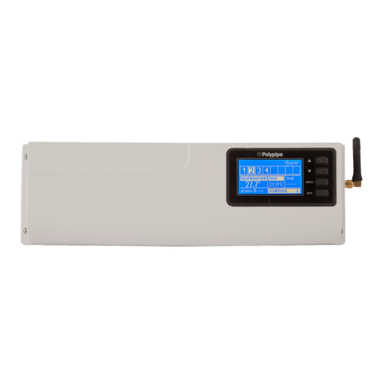
- Page 1 User’s manual User’s manual UFH8ZMP - 8 Zone RF Premium UFH8ZMP - 8 Zone RF Premium Wiring Centre Wiring Centre www.polypipeufh.com...
- Page 2 User’s manual...
-
Page 3: Table Of Contents
UFH8ZMP Table of contents Safety Description of the device II.a) Principle of operation III. Controller installation III.a) First start-up Wireless communication Main screen description and view Controller function VI.a) Block diagram of the menu VI.b) Manual operation VI.c) Zones VI.d) Language VI.e) Display contrast... -
Page 4: Safety
User’s manual I. Safety Before using the device for the fi rst time the user should read the following regulations carefully. Not obeying the rules included in this manual may lead to personal injuries or controller damage. The user’s manual should be stored in a safe place for further reference. -
Page 5: Description Of The Device
UFH8ZMP Description of the device UFH8ZMP wiring centre is intended for wireless control of the valves (see: Wireless communication). The controller enables signifi cant energy saving due to precise temperature management in particular rooms. Due to advanced software, the controller fulfi... -
Page 6: Controller Installation
User’s manual III. Controller installation The controller should be installed by a qualifi ed person. WARNING Risk of fatal electric shock from touching live connections. Before working on the controller switch off the power supply and prevent it from being accidentally switched on. -
Page 7: Iii.a) First Start-Up
In order for the controller to operate correctly, the user must follow these steps when starting the device for the fi rst time: 1. Connect UFH8ZMP with all the subordinate devices to be controlled 2. Switch on the power supply and check if the devices work. - Page 8 User’s manual Thermostats that require a power supply can be wired into any of the 3 provided connections. Two thermostats can be wired into the same connection allowing power to 6 thermostats. Thermostats can also be wired in a ‚daisy chain’ formation or powered by a seperate electrical circuit, to allow power for upto 8 thermostats if required.
- Page 9 UFH8ZMP Pictorial diagram presenting wiring and communication with other devices in the system.
- Page 10 Use ▲ and ▼ to select the device and press MENU – the device should switch on. Follow this procedure to check all the devices. STEP 3: Activate the Internet module UFH8ZMP external controller is compatible with UFHINTMODP and UFHINTWIFIP Internet modules. UFHINTWIFIP uses WiFi wireless network whereas UFHINTMODP needs to be connected to a router with RJ45 network cable.
- Page 11 Set current time and date in the fi tter’s menu. Step 5. Confi gure temperature sensors / room regulators To enable UFH8ZMP external controller to control a given zone, it is necessary to provide it with current temperature value. The easiest way is to use temperature sensor. If the...
- Page 12 It is possible to set individual pre-set temperature value and weekly schedule for each room sensor / regulator assigned to a given zone. The settings may be confi gured both in the controller menu (Main menu/Sensors) and via polypipe.emodul.eu (using Internet module).
-
Page 13: Wireless Communication
UFH8ZMP Wireless communication It is possible to establish wireless communication between UFH8ZMP external controller and certain devices: Function Confi guration UFHSENSEWP The sensor must – room - sending current zone be registered in a temperature temperature given zone. sensor - sending current zone... -
Page 14: Main Screen Description And View
User’s manual Main screen description and view The user navigates in the menu structure using the buttons located next to the display 1. Display 2. ▲- „up” „plus” – it is used to view the menu options and increase the value while editing parameters. - Page 15 UFH8ZMP 1. An icon indicating valve operation 2. An icon indicating that the additional contact is switched on 3. Current time 4. Time left until the manually set temperature in a given zone changes 5. Information about the type of current weekly schedule 6.
-
Page 16: Controller Function
User’s manual Controller function Due to multiple function fulfi lled by the controller, the menu is divided into Main menu and Fitter’s menu. VI.a) Block diagram of the menu... -
Page 17: Vi.b) Manual Operation
UFH8ZMP VI.b) Manual operation This function enables the user to activate particular devices (pump, voltage-free contact and valve actuators) independently of the others it order to check if they operate properly. In is advisable to check the devices using this procedure at the fi rst start-up. - Page 18 User’s manual • Weekly control The controller off ers two types of weekly schedules: Own – local schedule This weekly schedule is assigned to a given zone only. After the room sensor has been detected by the external controller, the schedule is activated automatically in this zone and may be adjusted by the user to individual needs.
-
Page 19: Vi.d) Language
Internet. Such online control is possible only after purchasing and connecting an additional module. The Internet module may be connected to UFH8ZMP via RS cable. After it has been connected, select Registration. The controller generates a code which the user should enter on the Internet website. -
Page 20: Protections And Alarm
Temperature protection. UFH8ZMP external controller is equipped with thermal protection which disconnects UFH8ZMP from the power supply when the protection temperature has been exceeded. WARNING !!!This item must be connected in order to start the controller.!!! -
Page 21: Software Update
UFH8ZMP VIII. Software update WARNING Software update shall be conducted only by a qualifi ed fi tter. After the software has been updated, it is not possible to restore previous settings. In order to install new software, the controller must be unplugged from the power supply. - Page 22 User’s manual...
- Page 23 UFH8ZMP...
- Page 24 Polypipe Building Products Broomhouse Lane Edlington Doncaster DN12 1ES +44 1709 770000 www.polypipeufh.com...
Need help?
Do you have a question about the UFH8ZMP and is the answer not in the manual?
Questions and answers