Table of Contents
Advertisement
Quick Links
Advertisement
Table of Contents

Related Manuals for Hanwha Vision XNP-C9310R


Summary of Contents for Hanwha Vision XNP-C9310R
- Page 1 NETWORK CAMERA User Manual XNP-C9310R XNP-C7310R...
- Page 2 Network Camera User Manual Copyright ©2023 Co., Ltd. All rights reserved. Hanwha Vision Trademark Each of trademarks herein is registered. The name of this product and other trademarks mentioned in this manual are the registered trademark of their respective company. Restriction Copyright of this document is reserved.
- Page 3 overview IMPORTANT SAFETY INSTRUCTIONS 22. If your product works normal, the degree of preset precision is 0.07˚. In the case of reboot due to outage, firmware upgrade, etc., its tolerance might have to be adjusted after checking for any changes in Preset setup. 1.
- Page 4 To Prevent damage which may caused by IR LED, don't stare at operating lamp. The ITE is to be connected only to PoE networks without routing to the outside plant. For below models only. XNP-C9310R XNP-C7310R The wired LAN hub providing power over the Ethernet (PoE) in accordance with IEEE 802.3bt shall be a UL Listed device with the output evaluated as a Limited Power Source as...
-
Page 5: Table Of Contents
CONTENTS OVERVIEW Important Safety Instructions WEB VIEWER Connecting to the Camera Recommended PC Specifications Password setting Recommended Micro SD/SDHC/SDXC Login Memory Card Specifications Camera Web Viewer Setup NAS recommended specs What’s Included Network I/O box - separately sold product Optional Accessories for Installation APPENDIX Troubleshooting At a Glance... -
Page 6: Recommended Pc Specifications
overview RECOMMENDED PC SPECIFICATIONS NAS RECOMMENDED SPECS ~ CPU : Intel(R) Core(TM) i7 3.4 GHz or higher ~ Recommended capacity : 200GB or higher is recommended. ~ RAM : 8G or higher ~ For this camera, you are recommended to use a NAS with the following manufacturer’s specs. ~ Recommended browser: Chrome Recommended products : QNAP NAS, Synology NAS ~ Supported browsers: Chrome, Safari, Firefox, MS Edge(chromium based) -
Page 7: What's Included
WHAT’S INCLUDED NETWORK I/O BOX - SEPARATELY SOLD PRODUCT Please check if your camera and accessories are all included in the product package. Appearance Item Name Description Model Name (As for each sales country, accessories are not the same.) Appearance Item Name Quantity Description... -
Page 8: Optional Accessories For Installation
overview OPTIONAL ACCESSORIES FOR INSTALLATION You can purchase appropriate optional accessories available. Wall & Pole Mount Hanging Mount Corner Mount Cabinet SBP-156WMW (Outdoor Wall&Pole Mount) * Direct assembly: SBP-156HMW not necessary SBP-156KMW SBP-156HMW SBP-300NBW SBP-300PMW2 (Pole Mount) SBP-300KMW1 SBP-390WMW2 (Wall Mount) * Only compatible when SBP-390WMW2 is used * SBP-156HMW required for installation * SBP-300PMW2 required for pole installation... - Page 9 Ceiling Mount Parapet Mount Assembly Individual Parts SBP-C15P SBP-180CMB SBP-140CMB SBP-180CMS SBP-150CMI (Ball Head) SBP-300CMTS SBP-300CMI SBP-156LMW SBP-300CMW1 (Ball Head) SBP-156CMW * SBP-156HMW required (Telescopic) SBP-150CMP SBP-900CMW (Telescopic) * SBP-156HMW required for installation SBP-300CMP * SBP-156HMW required for installation SBP-900CMP for installation English _9...
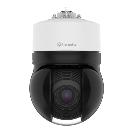
- Page 10 overview AT A GLANCE Inside Appearance Item Description Main cover Protects the internal PTZ mechanism from the direct sunlight, rain or external impact. Dome cover Shield cover for the lens and unit protection. The Micro SD card slot and reset button are located inside and can be opened using Torx Item Description Micro SD Card cover...
- Page 11 Mounting surface Item Description Cable bushing A waterproof rubber cap, which allows a network cable to go through it. Hang this hook on the safety wire of the mount when installing this product to prevent it Safety wire hook from falling. A port that connects to the HPoE injector and network cable for power and network Network port connection.
-
Page 12: Installation & Connection
installation & connection INSTALLATION 2. Slide a flathead screwdriver into the groove and flip the micro SD card slot cover open to the side. This camera is waterproof and in compliance with the IP67 spec, but the jack connected to the external cable is not. You are recommended to install this product below the edge of eaves to prevent the cable from being externally exposed. - Page 13 3. Insert Micro SD cards in the direction of the arrows as shown in the figure. Removing a Micro SD card Gently press down on the exposed end of the Micro SD card as shown in the diagram to eject the Micro SD card from the slot.
- Page 14 overview Installing using wall & pole mount 3. Remove the cable bushing from the bushing cover. Connect the power only after installation is complete. Supplying power while the installation is in progress may cause fire or damage the product. 1. Hang the safety wire of the wall & pole mount on the safety wire hook of the product. Safety wire Safety wire hook 4.
- Page 15 6. For waterproof protection, pull down the cable below the cable bushing as shown in the figure below. Make sure the cable bushing is also properly fitted on the inner surfaces of the bushing cover. If the cable bushing is inserted incorrectly, it may cause an issue with waterproofing.
- Page 16 installation & connection 9. Attach the bushing cover to the installation surface using the Torx screwdriver. 11. After aligning the installation direction guides of the camera and wall & pole mount, push the main cover upward and turn it counterclockwise until it is secured. TR10 10.
- Page 17 13. Join the top cover of the wall & pole mount. Installing using ceiling or parapet mount 1. Hang the safety wire of the mount on the safety wire hook of the product. Safety wire Safety wire hook 2. Remove the bushing cover from the installation surface using the Torx screwdriver. TR10 English _17...
- Page 18 installation & connection 3. Remove the cable bushing from the bushing cover. 6. For waterproof protection, pull down the cable below the cable bushing as shown in the figure below. 9~10 cm 7. Insert the cable bushing, threaded with the network cable, into the hole on the bushing cover. When plugging it in, press the whole bushing area evenly so that it is properly plugged in.
- Page 19 9. Attach the bushing cover to the installation surface using the Torx screwdriver. Make sure the cable bushing is also properly fitted on the inner surfaces of the bushing cover. If the cable bushing is inserted incorrectly, it may cause an issue with waterproofing. TR10 10.
- Page 20 installation & connection 11. After aligning the installation direction guides of the hanging mount, push the main cover upward and ` Joined with official product mounts (ceiling/parapet) turn it counterclockwise until it is secured. Ceiling Mount Parapet Mount 12. Tightly fasten the 3 mounting screws on the top side of the mount. (SBP-156CMW) (SBP-156LMW) TR30...
- Page 21 ` Joined with mounts other than official product mounts If you use hanging mount, you can install the camera onto any mount other than the official product mount. Wall Mount (SBP-390WMW2) Hanging Mount (SBP-156HMW) Ceiling Mount (SBP-300CMW1) Hanging Mount (SBP-156HMW) English _21...
-
Page 22: Powering And Networking
installation & connection POWERING AND NETWORKING Network Cable Specification Connect the HPoE injector with the HPoE port of the camera. Item Contents Remark Connector RJ45 (10/100BASE-T) Ethernet 10/100BASE-T External internet Cable UTP Category 5e SFP Port Max Distance 100 m DC Resistance ≤... -
Page 23: Connecting Audio And Alarm I/O
CONNECTING AUDIO AND ALARM I/O You can connect audio and alarm using a network I/O box separately sold. Microphone Network Speaker <SPM-4210> Sensor Alarm (Warning lamp) For more information on the network I/O box, see the manual for the network I/O box. You can set the network I/O box in Camera web viewer <Setup ( )>... -
Page 24: Network Connection And Setup
network connection and setup You can set up the network settings according to your network configurations. CONNECTING THE CAMERA DIRECTLY TO A DHCP BASED DSL/CABLE MODEM CONNECTING THE CAMERA DIRECTLY TO LOCAL AREA NETWORKING Connecting to the camera from a local PC in the LAN 1. -
Page 25: Using Device Manager
If using a Broadband Router ~ IP Address : Enter an address falling in the IP range provided by the Broadband Router. Device manager program can be downloaded from <Support>-<Online Tool> menu at Hanwha Vision website ex) 192.168.1.2~254, 192.168.0.2~254, (https://www.HanwhaVision.com). -
Page 26: Manually Registering Camera
~ Example of the Dynamic IP environment configure the IP. XNP-C9310R - If a Broadband Router, with cameras connected, is assigned an IP address by the DHCP server 2. Click < + > at the main page of device manager. -
Page 27: Port Range Forward (Port Mapping) Setup
PORT RANGE FORWARD (PORT MAPPING) SETUP Setting up Port Range Forward for several network cameras ~ You can set a rule of Port Forwarding on the Broadband Router device through its configuration web page. If you have installed a Broadband Router with a camera connected, you must set the port range forwarding on the ~ A user can change each port using the camera setting screen. -
Page 28: Connecting To The Camera From A Shared Local Pc
network connection and setup CONNECTING TO THE CAMERA FROM A SHARED LOCAL PC 1. Run device manager. It will scan for connected cameras and display them as a list. 2. Double-click a camera to access. The Internet browser starts and connects to the camera. Access to the camera can also be gained by typing the camera’s IP address in the address bar of the Internet browser. -
Page 29: Connecting To The Camera
web viewer CONNECTING TO THE CAMERA Connecting via Bonjour 1. Run the client or operating system in support of the Bonjour protocol. Normally, you would 2. Click the camera name for search. In the Mac operating system, click the camera name searched from the Bonjour tab of Safari. 1. -
Page 30: Password Setting
web viewer PASSWORD SETTING CAMERA WEB VIEWER SETUP When you access the product for the first time, you must register the 1. Click the [Setup ( )] icon. login password. 2. The Settings window appears. 3. You can configure settings for the camera’s basic information, video, audio, network, event, analysis, and For a new password with 8 to 9 characters, you must use at least system over the network. -
Page 31: Troubleshooting
appendix TROUBLESHOOTING PROBLEM SOLUTION PROBLEM SOLUTION ~ On the authentication popup window prompted when initially accessing https, click "View ~ Verify the settings in the following sequence: <Motion detection> of <Analytics> is Authentication Certificate" and select the "Always trust when connecting to the designated set to <Enable>, but no notification A. - Page 32 Operation of this equipment in a residential area is likely to cause harmful interference in which case the user will be required to correct the interference at his own expense. Hanwha Vision cares for the environment at all product manufacturing stages, and is taking measures to provide customers with more environmentally friendly products.
Need help?
Do you have a question about the XNP-C9310R and is the answer not in the manual?
Questions and answers