
Related Manuals for Hanwha Vision XNP-9250


Summary of Contents for Hanwha Vision XNP-9250
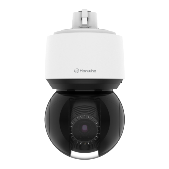
- Page 1 NETWORK CAMERA User Manual XNP-9250R/XNP-9250 XNP-8250R/XNP-8250 XNP-6400R/XNP-6400...
- Page 2 Network Camera User Manual Copyright ©2020 Co., Ltd. All rights reserved. Hanwha Vision Trademark Each of trademarks herein is registered. The name of this product and other trademarks mentioned in this manual are the registered trademark of their respective company. Restriction Copyright of this document is reserved.
- Page 3 EXPLANATION OF GRAPHICAL SYMBOLS 16. This product is intended to be supplied by a Listed Power Supply Unit marked “Class 2” or “LPS” and rated from PoE(53 Vdc), 0.48 A.(XNP-9250/XNP-8250/XNP-6400) The lightning flash with arrowhead symbol, within an equilateral triangle, is 17.
- Page 4 The wired LAN hub providing power over the Ethernet (PoE) in accordance with IEEE XNP-6400R 802.3at shall be a UL Listed device with the output evaluated as a Limited Power Source as defined in UL60950-1 or PS2 as defined in UL62368-1.(XNP-9250/XNP-8250/XNP-6400) Risk Group 1 WARNING IR emitted from this product.
-
Page 5: Table Of Contents
CONTENTS OVERVIEW Important Safety Instructions WEB VIEWER Connecting to the Camera Recommended PC Specifications Password setting Recommended Micro SD/SDHC/SDXC Login Memory Card Specifications Camera Web Viewer Setup NAS recommended specs What’s Included Network I/O box - separately sold product Optional Accessories for Installation APPENDIX Troubleshooting At a Glance... -
Page 6: Recommended Pc Specifications
overview RECOMMENDED PC SPECIFICATIONS NAS RECOMMENDED SPECS ~ CPU : Intel(R) Core(TM) i7 3.4 GHz or higher ~ Recommended capacity : 200GB or higher is recommended. ~ RAM : 8G or higher ~ For this camera, you are recommended to use a NAS with the following manufacturer’s specs. ~ Supported OS : MS Windows 8.1, 10, Mac OS X 10.13 Recommended products : QNAP NAS, Synology NAS ~ Recommended browser: Google Chrome... -
Page 7: What's Included
OPTIONAL ACCESSORIES FOR INSTALLATION Quick Guide You can purchase appropriate optional accessories available. (Optional) Used to connect the Cap Installer network cable XNP-9250R/XNP-9250/ XNP-8250R/XNP-8250/ XNP-6400R/XNP-6400 Used as a means of preventing cable bushing Bushing clip from being separated or falling apart from the hole. - Page 8 overview AT A GLANCE Inside(XNP-9250R/XNP-8250R/XNP-6400R) Appearance Item Description Main cover Protects the internal PTZ mechanism from the direct sunlight, rain or external impact. Dome cover Shield cover for the lens and unit protection. Item Description Micro SD Card cover Covers micro SD card slots and the Reset button. You can open it using the Torx L wrench. IR LED These infrared LED’s are controlled by the illumination sensor.
- Page 9 Inside(XNP-9250/XNP-8250/XNP-6400) Mounting surface Item Description Cable bushing A waterproof rubber cap, which allows a network cable to go through it. Hang this hook on the safety wire of the mount when installing this product to prevent it Safety wire hook from falling.
-
Page 10: Installation & Connection
installation & connection INSTALLATION 2. Push in a flathead screwdriver under the slot to pull out the Micro SD card slot. This camera is waterproof and in compliance with the IP66 spec, but the jack connected to the external cable is not. You are recommended to install this product below the edge of eaves to prevent the cable from being externally exposed. - Page 11 Removing a Micro SD card Gently press down on the exposed end of the Micro SD card as shown in the diagram to eject the Micro SD card from the slot. 4. After inserting the Micro SD cards, push the Micro SD card slot until it clicks into place. 5.
- Page 12 overview Getting ready for network cable installation 4. For waterproof protection, pull down the cable below the cable bushing as shown in the figure below. 1. Remove the cable bushing. 9~10 cm Installing using wall & pole mount Connect the power only after installation is complete. Supplying power while the installation is in progress may cause fire or damage the product.
- Page 13 2. Connect the network cable to the network port. 4. Install the bushing clip. Let the arrow mark on the clip point in the direction of the safety wire hook, and click each side into place one at a time. 3.
- Page 14 installation & connection 6. Tightly fasten the 3 mounting screws on the inside of the Wall & Pole Mount. Installing using ceiling or parapet mount 1. Hang the safety wire of the mount on the safety wire hook of the product. TR30 Safety wire Safety wire hook...
- Page 15 3. Plug the cable bushing of the network cable in the hole. 5. After aligning the installation direction guides of the hanging mount, push the main cover upward and turn When plugging it in, press the whole bushing area evenly so that it is properly plugged in. it counterclockwise until it is secured.
- Page 16 installation & connection ` Joined with official product mounts (ceiling/parapet) Ceiling Mount (SBP-300CMW) Hanging Mount (SBP-156HMW) Ceiling Mount Parapet Mount (SBP-156CMW) (SBP-156LMW) ` Joined with mounts other than official product mounts If you use hanging mount, you can install the camera onto any mount other than the official product mount. Parapet Mount (SBP-300LMW) Hanging Mount...
-
Page 17: Powering And Networking
Use a PoE+ device that complies with the IEEE 802.3at standard. (XNP-9250/XNP-8250/XNP-6400) Do not directly look at the optical cable. It can damage your eyes. If you connect using an PoE+ -enabled router, you don’t need a separate power supply cable to power it on.(XNP-9250/ XNP-8250/XNP-6400) Use only either one of network cable or fiber optic cable for connection. - Page 18 installation & connection Connecting audio and alarm I/O You can connect audio and alarm using a network I/O box separately sold. Microphone Network Speaker <SPM-4210> Sensor Alarm (Warning lamp) For more information on the network I/O box, see the manual for the network I/O box. You can set the network I/O box in Camera web viewer <Setup ( )>...
-
Page 19: Network Connection And Setup
network connection and setup CONNECTING THE CAMERA DIRECTLY TO A DHCP BASED DSL/CABLE You can set up the network settings according to your network configurations. MODEM CONNECTING THE CAMERA DIRECTLY TO LOCAL AREA NETWORKING Connecting to the camera from a local PC in the LAN INTERNET 1. -
Page 20: Using Device Manager
If using a Broadband Router ~ IP Address : Enter an address falling in the IP range provided by the Broadband Router. Device manager program can be downloaded from <Support>-<Online Tools> menu at Hanwha Vision website ex) 192.168.1.2~254, 192.168.0.2~254, (https://www.HanwhaVision.com). -
Page 21: Manually Registering Camera
AUTOMATICALLY CONFIGURING IP Configuring Dynamic IP Receive IP address from DHCP 1. Click the camera from the list that you want to automatically ~ Example of the Dynamic IP environment configure the IP. XNP-9250R - If a Broadband Router, with cameras connected, is assigned an IP address by the DHCP server 2. -
Page 22: Port Range Forward (Port Mapping) Setup
network connection and setup PORT RANGE FORWARD (PORT MAPPING) SETUP Setting up Port Range Forward for several network cameras ~ You can set a rule of Port Forwarding on the Broadband Router device through its configuration web page. If you have installed a Broadband Router with a camera connected, you must set the port range forwarding on the ~ A user can change each port using the camera setting screen. -
Page 23: Connecting To The Camera From A Shared Local Pc
CONNECTING TO THE CAMERA FROM A SHARED LOCAL PC 1. Run device manager. It will scan for connected cameras and display them as a list. 2. Double-click a camera to access. The Internet browser starts and connects to the camera. Access to the camera can also be gained by typing the camera’s IP address in the address bar of the Internet browser. -
Page 24: Connecting To The Camera
web viewer CONNECTING TO THE CAMERA Connecting via Bonjour 1. Run the client or operating system in support of the Bonjour protocol. Normally, you would 2. Click the camera name for search. In the Mac operating system, click the camera name searched from the Bonjour tab of Safari. 1. -
Page 25: Password Setting
PASSWORD SETTING CAMERA WEB VIEWER SETUP When you access the product for the first time, you must register the 1. Click the [Setup ( )] icon. login password. 2. The Settings window appears. 3. You can configure settings for the camera’s basic information, video, audio, network, event, analysis, and For a new password with 8 to 9 digits, you must use at least 3 of system over the network. -
Page 26: Troubleshooting
appendix appendix TROUBLESHOOTING PROBLEM SOLUTION PROBLEM SOLUTION ~ On the authentication popup window prompted when initially accessing https, click "View ~ Verify the settings in the following sequence: <Motion detection> of <Analytics> is Authentication Certificate" and select the "Always trust when connecting to the designated set to <Enable>, but no notification A. - Page 27 Operation of this equipment in a residential area is likely to cause harmful interference in which case the user will be required to correct the interference at his own expense. Hanwha Vision cares for the environment at all product manufacturing stages, and is taking measures to provide customers with more environmentally friendly products.
Need help?
Do you have a question about the XNP-9250 and is the answer not in the manual?
Questions and answers