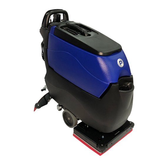
Pacific S-20 Manual
11 gallon autoscrubber
Hide thumbs
Also See for S-20:
- Parts & operating manual (58 pages) ,
- Parts & operating manual (64 pages)
Table of Contents
Advertisement
Quick Links
Thank you for purchasing a Pacific Floorcare product. Carefully inspect all components for freight damage. If such dam-
age is discovered, file a "CONCEALED DAMAGE REPORT" immediately with the delivering carrier.
Read this manual carefully and keep it near the machine, protected from liquids and other damaging substances. Failure to
follow the instructions may result in injury or damage to equipment and property.
The contents of this manual are based on the latest product information available at the time of publication. Pacific Floor-
care reserves the right to make changes or improvements without being obliged to apply changes to the machines previ-
New manuals can be downloaded from:
S-20 / S-24XM
S-20 / S-24XM
11 GALLON AUTOSCRUBBER
11 GALLON AUTOSCRUBBER
ously sold.
www.pacificfloorcare.com/manuals
Advertisement
Table of Contents

Related Manuals for Pacific S-20


Summary of Contents for Pacific S-20
- Page 1 The contents of this manual are based on the latest product information available at the time of publication. Pacific Floor- care reserves the right to make changes or improvements without being obliged to apply changes to the machines previ- ously sold.
- Page 2 11 GALLON AUTOSCRUBBER SPECIFICATIONS Features Specifications Model S-20 Disk Pad Assist S-20 Disk Transaxle Drive S-20HD Disk Transaxle Drive Solution Delivery System Solution Capacity: 11 gal / 42 l 11 gal / 42 l 11 gal / 42 l Solution Control: 0-.5 gpm / 1-1.9 lpm...
- Page 3 11 GALLON AUTOSCRUBBER SPECIFICATIONS Features Specifications Model: S-20 Orbital S-24XM Disk Solution Delivery System Solution Capacity: 11 gal / 42 l 11 gal / 42 l Solution Control: 0-.5 gpm / 1-1.9 lpm 0-.5 gpm / 1-1.9 lpm Variable Knob Adjustment...
-
Page 4: Table Of Contents
PAD ASSIST DISK SCRUB HEAD ...........................49 TRACTION DISK SCRUB HEAD ..........................51 S-20HD DISK SCRUB HEAD ............................53 ORBITAL SCRUB HEAD ............................55 S-24XM SCRUB HEAD .............................59 ELECTRICAL DIAGRAMS ����������������������������������������������������������������������������������������������������������������������������������������������61 S-20 TRACTION (DISK) & S-24XM .........................61 S-20 ORBITAL ................................63 S-20 PAD/BRUSH ASSIST ............................65 OPTIONAL SCRUBSMART TELEMETRY SYSTEM .....................66... - Page 5 PAGE INTENTIONALLY BLANK...
-
Page 6: Safety Information
SAFETY INFORMATION This machine is intended for commercial use. Only use recommended pads or brushes and commercially approved floor cleaning chemicals intended for machine application. WARNING: A potentially hazardous situation that, if not avoided, could result in death or serious injury� CAUTION: A potentially hazardous situation that, if not avoided, could result in moderate injury or serious property damage�... - Page 7 SAFETY INFORMATION CONTINUED CAUTION: Keep hands away from spinning brushes. CAUTION: Do not modify the machine from its original design. CAUTION: Wear non-slip shoes when operating machine. CAUTION: Reduce speed when turning or operating on inclines and slippery surfaces. CAUTION: Use Bromine only in your tank treatment system! Do not use chlorine.
-
Page 8: Unpacking The Machine
UNPACKING THE MACHINE Remove outer cardboard packaging. Remove the shrink wrap securing the ramp and allow the ramp (not shown) to lower to the ground. Using a #2 Philips driver, remove the screws from the front and rear wood wheel chocks. Using a 3/8”... -
Page 9: Batteries
BATTERIES WARNING: Battery posts, terminals, and related accessories contain lead and lead compounds, chemicals known to the State of California to cause cancer and reproductive harm, and during charging, strong inorganic acid mists containing sulfuric acid are involved, a chemical known to the State of California to cause cancer. Wash hands after handling. For more information go to www.P65Warnings.ca.gov. -
Page 10: Servicing Lead Acid Batteries (Non-Hydrolink ® Models)
SERVICING LEAD ACID BATTERIES (NON-HYDROLINK MODELS) ® REQUIRED EQUIPMENT • Eye protection • Acid resistant gloves • Distilled water • Baking soda to neutralize acid spills SAFETY NEVER: • Add acid to a battery. • Smoke near batteries. • Charge a frozen battery. •... -
Page 11: Servicing Lead Acid Batteries With Hydrolink ® Watering System
SERVICING LEAD ACID BATTERIES WITH HYDROLINK WATERING ® SYSTEM Position the container of distilled water below the level of the top of the batteries to prevent siphoning. Place the end of the watering system hose in the distilled water and squeeze the bulb to fill the system. Remove the dust cover from the Hydrolink snake connected to the batteries. -
Page 12: Cleaning The Batteryshield ® Sensor Light Pipe
CLEANING THE BATTERYSHIELD SENSOR LIGHT PIPE ® CAUTION: Always wear protective clothing, gloves and goggles when handling and charging batteries. NOTE: All repairs must be performed by a qualified service technician using approved replacement parts. Locate and remove the battery cap with the BatteryShield sensor module. -
Page 13: Charging
CHARGING WARNING: Batteries emit hydrogen and oxygen gas. • Keep sparks and open flame away. • Do not smoke near the machine. • Charge batteries in a well-ventilated area with the battery compartment open. WARNING: Do not wear jewelry when working near moving or electrical components. WARNING: Do not plug in the charger cable if wall cord or battery harness is damaged. -
Page 14: Off-Board Charging
OFF-BOARD CHARGING WARNING: This product can expose you to chemicals including lead and lead compounds which are known to the State of California to cause cancer and birth defects or other reproductive harm. For more information go to www. P65Warnings.ca.gov. WARNING: Batteries emit hydrogen and oxygen gas. -
Page 15: Operation
OPERATION MACHINE OVERVIEW A. SCRUB HEAD F. RECOVERY HOSE J. CONTROL PANEL B. SOLUTION TANK G. REVERSE SWITCH K. SQUEEGEE LIFT LEVER C. FILL PORT H. RECOVERY DRAIN HOSE L. SQUEEGEE ASSEMBLY D. RECOVERY TANK I. SOLUTION SIGHT TUBE M. HEAD LIFT LEVER E. - Page 16 TURNING THE UNIT ON/OFF The key switch is located on the control panel. When the machine is not in use, remove the key and store it in a secure location. CIRCUIT BREAKERS The circuit breakers on the control panel protect the components from high amp-draw. In particular, the scrub head circuit will draw too many amps when overloaded by improper application setup.
-
Page 17: Drive System (Traction Models)
Telemetry-equipped machines have a keypad mounted on the upper right side of the control panel. After turning on the key switch, enter the operator code. Failure to enter a valid operator code will prevent the machine from functioning. Operator codes are generated and administered by your Pacific Distributor or your company’s management. -
Page 18: Scrub Head
SOLUTION FLOW Solution flow is controlled by the Solution Flow Control located on the Control Panel. When the Scrub Head in lowered, solution is delivered at a rate of 0 - 0.5 gpm (0 - 1.9 lpm) based upon the Solution Flow setting and the speed of the machine (flow rate increases or decreases with machine speed to prevent over/under distribution). -
Page 19: Orbital Scrub Head & Chemical-Free Finish Removal
ORBITAL SCRUB HEAD & CHEMICAL-FREE FINISH REMOVAL NOTE: Do not operate the Orbital Scrub Head without a pad installed. Operating the head without a pad will damage the Mighty-Lok face. ® NOTE: Use of caustic, high ph, or degreasing chemicals can decrease the service life of components, including the orbital head bearing. -
Page 20: Disk Scrub Head
DISK SCRUB HEAD DISK INSTALLATION NOTE: Do not operate the Disk Scrub Head without a pad installed on the pad driver. Operating the head without a pad will damage the floor. Turn the key switch on and rotate the speed control knob to the full slow position. Place the pad drivers or brushes on the floor in front of the scrub head. -
Page 21: Recovery System
RECOVERY SYSTEM RECOVERY TANK To drain and rinse the recovery tank: Remove the Recovery Drain Hose from the holder and lower the end into the drain location. Remove the press-fit cap from the Recovery Drain Hose, squeezing the restriction collar to control the flow. As the tank drains, lift the Recovery Tank to the open position. - Page 22 SQUEEGEE SYSTEM Squeegee Blades and system should be inspected and maintained regularly to achieve peak machine performance. REMOVAL & INSTALLATION Install: Align the slots in the squeegee assembly with the easy-grip knobs, attach the vacuum hose, and tighten the knobs. Remove: Loosen the easy-grip knobs, remove the vacuum hose, and remove the assembly.
- Page 23 INSPECTION & CLEANING Inspect both squeegee blades. Blades edges are considered worn if the edge is not clearly defined or if the edge is worn halfway through the thickness of the blade. Blades can be flipped and rotated to use all four edges. Thoroughly clean the blades, frame, and neck of any debris.
-
Page 24: Recommended Maintenance
RECOMMENDED MAINTENANCE SYSTEM DAILY WEEKLY MONTHLY BIANNUALLY CONTROL PANEL INSPECT CONTROLS AND HARDWARE FOR SECURITY & SERVICEABILITY VERIFY PROPER OPERATION OF ALL CONTROLS SOLUTION DISTRIBUTION VERIFY SOLUTION FLOW & ADJUSTMENT OPERATION CLEAN AND INSPECT INLINE FILTER FLUSH TANK WITH FRESH WATER SCRUB DECK RINSE BRUSHES &... - Page 25 PAGE INTENTIONALLY BLANK RETURN TO TABLE OF - 20 - CONTENTS...
-
Page 26: Recommended Service Parts
RECOMMENDED SERVICE PARTS PART NUMBER DESCRIPTION DIAGRAM WEAR ITEM S-20 PAD ASSIST DISK S-20 TRACTION DISK S-20 ORBITAL S-24XM OPTIONAL 903046 BELT, V-GROOVE, STRETCH SCRUB HEAD 850701 BLADE, FRONT, 30 INCH SQUEEGEE 850703 BLADE, FRONT, 30 INCH, URETH (OPTL) SQUEEGEE... - Page 27 DESCRIPTION DIAGRAM WEAR ITEM S-20 PAD ASSIST DISK S-20 TRACTION DISK S-20 ORBITAL S-24XM OPTIONAL 854105 HOSE SQUEEGEE S-20 CHEM RESIST RECOVERY TANK 854101 HOSE, DRAIN, CAPPED RECOVERY TANK 854102 HOSE, SQUEEGEE, 90 CUFF RECOVERY TANK 854103 HOSE, VACUUM, 1.5INCH...
- Page 28 RECOMMENDED SERVICE PARTS PART NUMBER DESCRIPTION DIAGRAM WEAR ITEM S-20 PAD ASSIST DISK S-20 TRACTION DISK S-20 ORBITAL S-24XM OPTIONAL 878504 STRAP, GROUNDING, STATIC SQUEEGEE LINK 911647 SWITCH, KEY CONTROLS 911649 SWITCH, ROCKER, AUTO ON-OFF CONTROLS 911653 SWITCH, ROUND, ON – MOM...
- Page 29 PAGE INTENTIONALLY BLANK RETURN TO TABLE OF CONTENTS...
-
Page 30: Troubleshooting Guide
TROUBLESHOOTING GUIDE ISSUE POTENTIAL CAUSE PROPOSED SOLUTION SOLUTION FLOW SETTING IS TOO LOW ADJUST SOLUTION CONTROL SOLUTION TANK IS EMPTY ADD WATER/SOLUTION TO THE TANK INLINE SOLUTION FILTER IS CLOGGED REMOVE AND CLEAN THE FILTER INSUFFICIENT WATER TO SCRUB HEAD SOLUTION TUBE IS CLOGGED, KINKED, OR DAMAGED INSPECT TUBES SOLUTION SHUT OFF VALVE IS CLOSED... - Page 31 TROUBLESHOOTING GUIDE ISSUE POTENTIAL CAUSE PROPOSED SOLUTION SCRUB HEAD IS STILL RAISED LOWER SCRUB HEAD BATTERYSHIELD® LED IS ILLUMINATED AND HAS DISABLED THE SCRUB HEAD (IF SERVICE THE BATTERIES EQUIPPED) BATTERIES ARE DISCHARGED BELOW THRESHOLD VOLTAGE CHARGE BATTERIES BRUSH MOTOR CIRCUIT BREAKER HAS TRIPPED SEE NEXT TOPIC ON THIS TABLE SCRUB HEAD WILL NOT RUN SCRUB HEAD LIFT ARM SWITCH MAY BE STUCK OR FAULTY...
-
Page 32: Parts Diagrams
PARTS DIAGRAMS FRAME ASSEMBLY ITEM PART NUMBER DESCRIPTION ALL TRACTION MODELS 853202 FRAME, SCRUBBER, 20 TRACT 962269 SCREW, HEX, .31-18 X .75, SS 980094 WASHER, SPLIT LOCK, .31, SS W243D WASHER, FLAT, 5/16, SS 859201 TRANSAXLE, 24VDC, 20 IN 870919 BRUSH KIT REPL FOR TRANSAXLE 859201 855206 MOTOR REPL FOR TRANSAXLE 859201... - Page 33 FRAME ASSEMBLY PAD ASSIST MODELS ITEM PART NUMBER DESCRIPTION 853201 FRAME, SCRUBBER, 20 BA 859702 WHEEL, BRG, 8 INCH W502D NUT, NYLOCK, 1/2-13, THIN, ZINC 857502 RIG CASTER 3INCH WITH AXLE 859709 WHEEL CASTER 3INCH 855015 KIT CASTER 3 INCH REPLACEMENT 980079 WASHER, FLAT, .5, ZINC 980019...
-
Page 34: Head Lift
HEAD LIFT DISK & PAD ASSIST MODELS ITEM PART NUMBER DESCRIPTION 850802 BRACKET, LIFT, HEAD 962279 SCREW, SOCKET CAP, .31X1.0, SS W243D WASHER, FLAT, 5/16, SS 853802 GUIDE, SPACER, ROUND 980612 WASHER, NYL, .50 X 1.25 X .062 920012 NUT, NYLOCK, 5/16-18, ZINC 962442 SCREW HH .25-20 X 1.75 SS 980002... - Page 35 HEAD LIFT ORBITAL MODELS ITEM PART NUMBER DESCRIPTION 850802 BRACKET, LIFT, HEAD 853801 GUIDE, LEVER 980093 WASHER, WAVE, .50INCH 980612 WASHER, NYL, .50 X 1.25 X .062 980094 WASHER, SPLIT LOCK, .31, SS 962279 SCREW, SOCKET CAP, .31X1.0, SS 962442 SCREW HH .25-20 X 1.75 SS 980002 WASHER, LOCK, SPLIT, .25...
- Page 36 HEAD LIFT S-24XM ITEM PART NUMBER DESCRIPTION 850802 BRACKET, LIFT, HEAD 853801 GUIDE, LEVER 980093 WASHER, WAVE, .50INCH 980612 WASHER, NYL, .50 X 1.25 X .062 980094 WASHER, SPLIT LOCK, .31, SS 962279 SCREW, SOCKET CAP, .31X1.0, SS 962442 SCREW HH .25-20 X 1.75 SS 980002 WASHER, LOCK, SPLIT, .25 W104D...
- Page 37 SOLUTION TANK ITEM PART NUMBER DESCRIPTION 858601 TANK, SOLUTION, 11 GAL 850814 BRACKET, SUPPORT, LEVER W189D SCREW, HEX, 1/4-20 X .75, SS, PATCH W104D WASHER, FLAT, .25 980002 WASHER, LOCK, SPLIT, .25 223343 FITTING, STR, BM08, PM08 853303 FITTING, STR, BM12, PM08 859003 TUBE, SIGHT, REPLACMENT S453P...
-
Page 38: Electronics
ELECTRONICS ITEM PART NUMBER DESCRIPTION 859801 PANEL, ELECTRONICS 859101 CONTROLLER, TRACTION, S20 980025 WASHER, SPLIT LOCK, #6, ZINC W323D SCREW, PAN, #6-32 X 1.0, ZINC 912402 CONTACTOR, 24VDC, 70A 912401 CONTACTOR, 24V, 100A 962363 SCREW, PAN, #10-32 X .50, SS W401D WASHER, FLAT, #10 980022... -
Page 39: Battery
BATTERY ITEM PART NUMBER DESCRIPTION BATTERYSHIELD® SENSOR IS MATED 851303 BATTERY, 12V, 155AH, LEAD ACID AND CALIBRATED TO THE MANIFOLD 841311 BATTERY, 12V, 140AH, AGM (BATT CAP) FROM THE FACTORY. 881350 BATTERY, 12V, 130AH, LEAD ACID SENSOR AND CAP MUST BE REPLACED 851302 BATTERY, 12V, 105AH, AGM AS AN ASSEMBLY –... -
Page 40: Controls
CONTROLS S-24XM & TRACTION MODELS RETURN TO TABLE OF CONTENTS... - Page 41 SCREW PHPS 4-40 X .75 SS BL 855004 KNOB OVAL .31-18 911661 METER, HOUR, DIGITAL (OPTIONAL) 878208 SPACER PLASTIC #10 X .25 THICK 855111 LABEL, QR CODE, S-20 872413 CONTROLLER FLOW WATER 911649 SWITCH, ROCKER, AUTO ON-OFF W401D WASHER, FLAT, #10 962263 SCREW BHCS .25-20 X .63 SS BL...
- Page 42 CONTROLS S-20HD RETURN TO TABLE OF CONTENTS...
- Page 43 SCREW PHPS 4-40 X .75 SS BL 855004 KNOB OVAL .31-18 911661 METER, HOUR, DIGITAL (OPTIONAL) 878208 SPACER PLASTIC #10 X .25 THICK 855111 LABEL, QR CODE, S-20 872413 CONTROLLER FLOW WATER 911649 SWITCH, ROCKER, AUTO ON-OFF W401D WASHER, FLAT, #10 962263 SCREW BHCS .25-20 X .63 SS BL...
- Page 44 CONTROLS ITEM PART NUMBER DESCRIPTION PAD ASSIST MODELS 857001 PANEL, CONTROLS 855101 LABEL, CONTROL, BA 911647 SWITCH KEY 962264 SCREW BHCS .25-20 X 1.75 SS BL 911649 SWITCH, ROCKER, AUTO ON-OFF 962263 SCREW BHCS .25-20 X .63 SS BL 962209 SCREW PHPS 4-40 X .75 SS BL 911646 SWITCH, SNAP, WITH ROLLER...
-
Page 45: Optional Scrubsmart Telemetry System
OPTIONAL SCRUBSMART TELEMETRY SYSTEM ITEM PART NUMBER DESCRIPTION W132D SCREW PAN #6-32 X 1.0 ZINC 980025 WASHER SPLIT LOCK #6 ZINC 895002 KEYPAD TELEMETRY TRACKING 962460 SCREW, #8X.75, PHIL TRUSS SS 850818 BRACKET MTG KEYPAD 878208 SPACER PLASTIC #10 X .25 THICK 870826 BRACKET MTG RELAY 911685... -
Page 46: Recovery Tank Assembly
RECOVERY TANK ASSEMBLY ***PRIOR TO SERIAL NUMBER 124471 – CONFIRM SERIAL NUMBER BEFORE ORDERING REPLACEMENT PARTS*** RETURN TO TABLE OF CONTENTS... -
Page 47: Recovery Tank Assembly
AVAILABLE VACUUM MOTOR KIT - #855019 ITEM QTY PART NUMBER DESCRIPTION ITEM DESCRIPTION 858602 TANK, RECOVERY, 11 GA 857802 SHEET INSTRUCTION S-20 VAC MTR REPL 852301 COVER, TANK, RECOVERY 853305 FOAM,NOISE,VACUUM 962462 SCREW, SHOULDER, .38 X 1.75, SS 911104 TIE-CABLE 14.5 LG 9531 H400014 H400002... - Page 48 RECOVERY TANK ASSEMBLY ***AFTER SERIAL NUMBER 124471 – CONFIRM SERIAL NUMBER BEFORE ORDERING REPLACEMENT PARTS*** RETURN TO TABLE OF CONTENTS...
- Page 49 AVAILABLE VACUUM MOTOR KIT - #855019 ITEM PART NUMBER DESCRIPTION ITEM DESCRIPTION 858602 TANK, RECOVERY, 11 GA 857802 SHEET INSTRUCTION S-20 VAC MTR REPL 223370 FLOAT, SHUTOFF 853305 FOAM,NOISE,VACUUM S611A CLAMP, HOSE, WORM 911104 TIE-CABLE 14.5 LG 9531 H400014 H400002 853402...
-
Page 50: Squeegee Linkage
SQUEEGEE LINKAGE ITEM PART NUMBER DESCRIPTION 850816 BRACKET LINK SQUEEGEE S-20 545010 KNOB KIT WEIGHT RETENTION 962464 SCREW, BUTTON, .31-18X1.25, ZINC 980105 WASHER, PLASTIC, THRUST 920040 NUT, .31-18, NYLOCK, SS, LOW 920036 NUT, NYLOCK, 5/16-18, SS 850501 AXLE, WHEEL, SQUEEGEE 849709 WHEEL, 2 OD, .31 ID... -
Page 51: Squeegee Assembly
SQUEEGEE ASSEMBLY LINATEX ASSEMBLY: 878516 URETHANE ASSEMBLY: 878517 ITEM PART NUMBER DESCRIPTION 853203 FRAME, SQUEEGEE, 30 INCH 850702 BLADE, REAR, 30 INCH 857201 RETAINER, REAR, 30 INCH 850701 BLADE, FRONT, 30 INCH 857202 RETAINER, FRONT, 30 INCH 852002 CLAMP, OVER-CENTER, BAND FRONT BLADE LENGTH: 31”... -
Page 52: On-Board Charger (Optional)
ON-BOARD CHARGER (OPTIONAL) ITEM PART NUMBER DESCRIPTION 850804 BRACKET, MTG, CHARGER W189D SCREW, HEX, 1/4-20 X .75, SS, PATCH 980002 WASHER, LOCK, SPLIT, .25 W104D WASHER, FLAT, .25 852407 CHARGER, 24V, ONBRD, CULUS 962186 SCREW, PAN, #10-32 X 1.0, SS W401D WASHER, FLAT, #10 920666... - Page 53 PAGE INTENTIONALLY BLANK RETURN TO TABLE OF CONTENTS...
-
Page 54: Pad Assist Disk Scrub Head
PAD ASSIST DISK SCRUB HEAD RETURN TO TABLE OF CONTENTS... - Page 55 PAD ASSIST DISK SCRUB HEAD ITEM PART NUMBER DESCRIPTION ITEM PART NUMBER DESCRIPTION 855201 MOTOR, GEAR, BRUSH 920011 NUT, NYLOCK, 1/4-20, ZINC 850905 BRUSH CARBON KIT 2 PC 855201 850808 BRACKET, SUPPORT, HEAD 962003 SCREW, PAN, #10-32 X .75, ZINC 920012 NUT, NYLOCK, 5/16-18, ZINC 612001...
-
Page 56: Traction Disk Scrub Head
TRACTION DISK SCRUB HEAD RETURN TO TABLE OF CONTENTS... - Page 57 TRACTION DISK SCRUB HEAD ITEM PART NUMBER DESCRIPTION ITEM PART NUMBER DESCRIPTION 855201 MOTOR, GEAR, BRUSH 857501 ROLLER, PLASTIC 850905 BRUSH CARBON KIT 2 PC 855201 920012 NUT, NYLOCK, 5/16-18, ZINC 962003 SCREW, PAN, #10-32 X .75, ZINC 920011 NUT, NYLOCK, 1/4-20, ZINC 612001 CLAMP, PLASTIC, P-SHAPED 850808...
-
Page 58: S-20Hd Disk Scrub Head
S-20HD DISK SCRUB HEAD RETURN TO TABLE OF CONTENTS... - Page 59 S-20HD DISK SCRUB HEAD ITEM PART NUMBER DESCRIPTION ITEM PART NUMBER DESCRIPTION 855207 MOTOR, GEAR, BRUSH 857501 ROLLER, PLASTIC 850905 BRUSH CARBON KIT 2 PC 855201 920012 NUT, NYLOCK, 5/16-18, ZINC 962003 SCREW, PAN, #10-32 X .75, ZINC 920011 NUT, NYLOCK, 1/4-20, ZINC 612001 CLAMP, PLASTIC, P-SHAPED 850808...
-
Page 60: Orbital Scrub Head
WASHER, SPLIT LOCK, .31, SS W405D NUT, .31-18, JAM, SS 920012 NUT, NYLOCK, 5/16-18, ZINC 855116 LABEL PATENT ORBITAL HEAD 859005 TUBE DISTRIBUTION S-20 ORB 856802 PLUG .62 TUBE 878302 SPRING COMPR .62L X .66DIA 878209 SPACER WHEEL GUIDE 980643... - Page 61 WASHER NYLON 1/2 ID 859703 WHEEL, GUIDE 878209 SPACER WHEEL GUIDE 962263 SCREW BHCS .25-20 X .63 SS BL 859005 TUBE DISTRIBUTION S-20 ORB 852003 CLAMP, P-SHAPED, .62 DIA 856603 PLATE, MOUNTING, MOTOR 964009 SCREW FHCS M6 X 16 SS PATCH W117D SCREW HH .25-20 X 2 SS...
- Page 62 962274 SCREW, FLAT, SOCK, .25-20X.62, SS, PATCH 8*** 856605 PLATE, RETAINER, BEARING 9*** ASSY, BEARING, ORBIT S-20 10*** 962280 SCREW, SET, .25-20X.5, SS, PATCH 856606 PLATE, BALANCE, 20 INCH *ITEMS 2 & 3 CAN BE ORDERED PRE-ASSEMBLED AS A KIT UNDER PART NUMBER 855011- KIT, PLATE, REPL, ORBIT.
- Page 63 8*** 856605 PLATE, RETAINER, BEARING 9*** 962280 SCREW, SET, .25-20X.5, SS, PATCH 10*** ASSY, BEARING, REPL, ORBIT S-20 11*** 547604 SEAL BEARING ORBITAL 856606 PLATE, BALANCE, 20 INCH *ITEMS 1 & 2 CAN BE ORDERED PRE-ASSEMBLED AS A KIT UNDER PART NUMBER 855031 - KIT ORB PLATE 20IN REPL GEN2.
-
Page 64: S-24Xm Scrub Head
S-24XM SCRUB HEAD ITEM PART NUMBER DESCRIPTION 876602 PLATE, MTG, 24 INCH 858203 SPACER, WHEEL, GUIDE W104D WASHER, FLAT, .25 W243D WASHER, FLAT, 5/16, SS 853803 GUIDE, DRIVER 873801 GUIDE, PAD, PLASTIC 857501 ROLLER, PLASTIC 962274 SCREW, FLAT, SOCK, .25-20X.62, SS, PATCH 962270 SCREW, HEX, 5/16-18X1.75,SS 920012... - Page 65 S-24XM SCRUB HEAD ITEM PART NUMBER DESCRIPTION 870902 BRUSH, POLY, 12 INCH 870908 BRUSH, NYLON, 12 INCH 870909 BRUSH, GRIT, 12 INCH 859703 WHEEL, GUIDE 875019 KIT SKIRT REPLACEMENT (ITEMS 6 - 10) 962263 SCREW, BUTT, SOCK, .25-20X.62, SS BO 920665 NUT, NYLOCK, 1/4-20, SS W104D...
-
Page 66: Electrical Diagrams
ELECTRICAL DIAGRAMS S-20 TRACTION (DISK) & S-24XM ***PRIOR TO SERIAL NUMBER 113191*** RETURN TO Wires represented with dashed lines indicate optional equipment installation TABLE OF CONTENTS... - Page 67 S-20 TRACTION (DISK) & S-24XM ***AFTER SERIAL NUMBER 113191*** RETURN TO Wires represented with dashed lines indicate optional equipment installation TABLE OF CONTENTS...
-
Page 68: S-20 Orbital
S-20 ORBITAL ***PRIOR TO SERIAL NUMBER 113191*** RETURN TO Wires represented with dashed lines indicate optional equipment installation TABLE OF CONTENTS... - Page 69 S-20 ORBITAL ***AFTER SERIAL NUMBER 113191*** RETURN TO Wires represented with dashed lines indicate optional equipment installation TABLE OF CONTENTS...
-
Page 70: S-20 Pad/Brush Assist
S-20 PAD/BRUSH ASSIST ALL SERIAL NUMBERS RETURN TO Wires represented with dashed lines indicate optional equipment installation TABLE OF CONTENTS... -
Page 71: Optional Scrubsmart Telemetry System
OPTIONAL SCRUBSMART TELEMETRY SYSTEM RETURN TO TABLE OF CONTENTS... - Page 72 DATE MAINTENANCE LOG RETURN TO TABLE OF - 67 - CONTENTS...
- Page 73 DATE MAINTENANCE LOG RETURN TO TABLE OF - 68 - CONTENTS...
- Page 74 REVISION REVISION LOG 2019.10.24 UPDATED BALLOONS FOR THE RECOVERY TANK, PAGE 37. 2019.11.27 ADDED BALLOON FOR THE VACUUM MOTOR, PAGE 37. 2020.2.5 ADDED ALL APPLICABLE INFORMATION FOR THE S-20HD & MISC. CORRECTIONS. 2020.2.13 ADDED MISSING SQUEEGEE ASSEMBLY PART NUMBERS, PAGE 42. 2020.2.20 UPDATE PART NUMBERS, PAGES 48 &...
- Page 75 PAGE INTENTIONALLY BLANK RETURN TO TABLE OF - 70 - CONTENTS...
- Page 76 www.pacificfloorcare.com...
Need help?
Do you have a question about the S-20 and is the answer not in the manual?
Questions and answers
poor water pick up