
Related Manuals for Engcon DC3


Summary of Contents for Engcon DC3
- Page 1 User manual Language Country Article 9000683 | Version 1.5 Original Instructions...
- Page 2 Dear Customer, Thank you for choosing a product from engcon. engcon is the market leader in tiltrotators and tools for excavators. We represent innovation, knowledge and experience, and we develop our products with a focus on the customer's needs. Please visit our website for contact information and details about the rest of our product range.
-
Page 3: Table Of Contents
3.4.1. Overview....................14 4. Installation 4.1. System overview DC3..................15 4.1.1. Tiltrotator control..................15 5. Operation 5.1. DC3 for Android and iOS................17 5.1.1. Getting started..................17 5.1.2. The tool application..................17 5.1.3. Soft assignment..................17 5.2. QSC Quick guide.................... 17 5.2.1. - Page 4 8.1.1. Alarm list....................35 8.2. Electronics module - QLM................35 8.2.1. Indications....................35 8.2.2. Alarm......................36 9. Decals 9.1. Joystick MIG2....................37 9.1.1. 841868..................... 37 9.1.2. 841869..................... 38 9.2. DC3 Control System..................38 9.2.1. MGM......................38 10. Glossary 10.1. Abbreviations....................39 11. Installation checklist...
-
Page 5: Introduction
1.2. Scrapping and recycling engcon makes constant efforts to reduce its environmental impact. engcon's products comprise at least 99 per cent recyclable material. All assembly and service work must take place in compliance with legislation and ordinances governing the environment, health and occupational safety. -
Page 6: Product Approval
1.4.1. Declaration of incorporation of a partly completed machine Product: engcon DC3 Control system Manufacturer: engcon Nordic AB - Industricentragatan 4, SE 833 93 Strömsund, Sweden THE OBJECT OF THE DECLARATION DESCRIBED ABOVE IS IN CONFORMITY WITH the essential and applicable requirements of 2006/42/EC. -
Page 7: Eu Declaration Of Conformity
This declaration of compliance applies to the control system but not to the equipment controlled by said system such as an engcon tiltrotator. The product has radio functions to allow setup and calibration of the system. -
Page 8: Safety
2 Safety 2. Safety REMARKS The stated safety information is independent of the base machine and directly concerns the engcon DC3. REMARKS Other safety instructions can be found in the tiltrotator user manual. 2.1. General It is important that you read and understand all warnings prior to installation work on this product or before you use it and any accessories supplied. -
Page 9: Safety Features According To 13849-1
2 Safety 2.2. Safety features according to 13849-1 DC3 is a safety system that complies with SS - EN ISO 13849-1:2016. This means there are risks in the system that are managed with the aid of software. RISK 1 Unexpected activation of tiltrotator functions. The risk is managed by safety function SF1 –... -
Page 10: Design And Function
3. Design and function 3.1. DC3 The DC3 is a proportional control system with remote support. Our DC3 control system meets the standards demanded of all components such as hydraulics, electronics and software. Together with engcon’s tiltrotators with their built-in safety functions, the DC3 creates a safer work environment and enables track and wheel control as well as boom slew. - Page 11 3 Design and function Bucket in Bucket out Stick in Stick out Float position Float position Scissors open Scissors close Leveling blade Leveling blade Leveling blade Support leg up/ down up/down down Support leg up Support leg Swing axle down locked Swing axle off Boom...
-
Page 12: Control Panel - Qpm
3 Design and function Hammer Horn Parking brake Crawler gear Constant flow Low gear High gear Power boost Power boost Windscreen Main beam/ User 2 USER 2 wipers dipped beam User 3 Extra function 1 Extra function 2 EXTRA USER 3 EXTRA Extra function Extra function... -
Page 13: Buttons
3 Design and function 3.3.2. Buttons Symbol Button press Steady light indicates that Initiates lock opening sequence Lock opening sequence can be initiated Ground contact is required Or 1 Overrides ground contact Or 2 Shows ground contact sensor status The sensor detects pressure Opens the lock The lock can be opened Closes the lock... -
Page 14: Electronics Module - Qlm
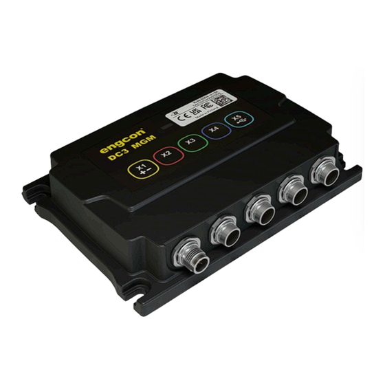
This means QLM will alert when connecting and disconnecting tools or if a tool is not properly connected. REMARKS For quick couplers other than Q-Safe, follow the manufacturer's instructions for checking that tools are correctly connected. 3.4.1. Overview DC3 MGM Position Description Power supply Alarm indication Sensor, machine coupler hook... -
Page 15: Installation
4 Installation 4. Installation 4.1. System overview DC3 4.1.1. Tiltrotator control Position Designation Electronics module - MGM Joystick - MIG2 Control panel - QPM Ground pressure sensor Electronics module - QLM Connector - ILME Tiltrotator... -
Page 16: Operation
Risk of injury. IMPORTANT Maintenance and repair of the electrical system may only be carried out by professionally qualified persons. IMPORTANT If you have any doubts concerning the safety aspects of your knowledge, the equipment or work, contact a dealer or engcon... -
Page 17: Dc3 For Android And Ios
5 Operation 5.1. DC3 for Android and iOS With the aid of the engcon DC3 app, you can adjust and set up your system with changes that suit you. Creating an account allows these settings to be backed up and available should you change your smartphone. -
Page 18: Tiltrotator Quick Coupler (Qh)
5 Operation 5.2.1. Tiltrotator quick coupler (QH) 5.2.2. Machine quick coupler... -
Page 19: Tiltrotator Quick Coupler (Qh)
Q-Safe quick coupler. 5.3.1. Connecting tools See separate instructions for use for the tiltrotator and machine coupler. Also available on the website or by contacting engcon. 1. Check that the indicator rod is out. - Page 20 5 Operation 2. Hold down for at least 3 seconds to close the quick coupler. 3. Check that the indicator rod is no longer visible and that the axle is in the correct position. 4. When the sound and light warning signals are deactivated, the tool is correctly connected.
-
Page 21: Disconnecting Tools
5 Operation 5.3.2. Disconnecting tools See separate instructions for use for the tiltrotator and machine coupler. Also available on the website or by contacting engcon. 1. The indicator rod is not visible when the lock is closed. 2. Press to initiate the sequence. - Page 22 5 Operation 4. Lower the tool to achieve ground contact. 5. The icon goes out when ground contact is achieved. 6. Raise the tool slightly above the ground to reduce the load during the locking operation. 7. Hold down for at least 3 seconds to open the quick coupler.
- Page 23 5 Operation 8. Check that the indicator rod is out.
-
Page 24: Start-Up
Risk of injury and damage to property. WARNING If you have any doubts concerning the safety aspects of your knowledge, the equipment or work, contact a dealer or engcon AB. Incorrect installation affect safety. IMPORTANT Assembly and installation may only be carried out at a workshop authorized by the manufacturer. -
Page 25: Connect Dc3 To Your Machine
S/N: 000123456789 DC3 MGM 6.2. Remote assistance No matter where you are, you can contact an engcon technician by using the built-in remote assistance. The technician can help you troubleshoot any problems you may have with your machine. 6.2.1. Request help You can request remote assistance by generating a 4-digit code that an engcon technician can use to connect to your machine. -
Page 26: Maintenance
7 Maintenance 7. Maintenance 7.1. Contact grease We recommend applying contact grease to electronics contacts to prevent corrosion. Remove any contaminants before application. Recommended grease: We recommend contact grease without destructive or corrosive properties and which is intended for use on electronic contacts for the prevention of corrosion. -
Page 27: Troubleshooting
8 Troubleshooting 8. Troubleshooting WARNING In the case of alarms that cannot be remedied, contact an authorized service provider ASAP. The fault must be remedied before the machine may be used again. Risk of injury and damage to property. WARNING Stop work immediately and begin troubleshooting if the system warns of a faulty tool connection during operation. -
Page 28: Control Panel - Qpm
8 Troubleshooting 8.1. Control panel - QPM Symbol Indication Description Action Constant light Machine limitation active Confirmation 1: Confirm by pressing the button. Confirmation is only possible when no configured quick coupler lock indicates an incorrectly connected lock. Confirmation 2: Confirm temporarily by holding in the button to enable machine movement when lock incorrectly... - Page 29 8 Troubleshooting Symbol Indication Description Action Ground pressure sensor fault. Alt 1: Configure QSC to use the Button not Alt 1: Wrong type of ground type of ground pressure sensor pressedSlow Flashes 1 time per pressure sensor selected. installed on the machine. second (1 Hz) Alt 2: (Digital ground pressure Alt 2: NO and NC signals indicate...
- Page 30 8 Troubleshooting Symbol Indication Description Action Steady light (both) Machine lock is active. Coil is energized. Off (both) Machine lock is inactive. Left indicator The hook sensor indicates it is Automatic when both sensors flashes at 10 times ‘not coupled’. Takes priority over indicate the same state, ‘coupled’...
- Page 31 8 Troubleshooting Symbol Indication Description Action Left indicator The hook sensor indicates it is Automatic when both sensors flashes at 10 times ‘not coupled’. Takes priority over indicate the same state, ‘coupled’ per second steady light. or ‘not coupled’. (10 Hz) Right indicator Ejector sensor indicates that it is Automatic when both sensors...
- Page 32 8 Troubleshooting Symbol Number of Name Description Confirmation flashes Pressure The current through Automatic when more than activation Valve 2 pressure activating 200 mA passes through Open Load (CV) valve 2 is less pressure valve 1 when it is than 200 mA when active.
- Page 33 8 Troubleshooting Symbol Number of Name Description Confirmation flashes Machine Sensor Supply voltage out Automatic when the supply supply short to the tiltrotator voltage to the machine circuit lock sensors is less sensors exceeds 50% of than 50% of system system voltage.
- Page 34 8 Troubleshooting Symbol Number of Name Description Confirmation flashes MCSE error Communication fault The system is restarted. between QCM2 and QPM. Button pressed on QPM at start-up. SS9-2 timeout Communication with Automatic when SS9 is selected in communication with SS9 is the configuration restored.
-
Page 35: Alarm List
8 Troubleshooting 8.1.1. Alarm list 8.2. Electronics module - QLM 8.2.1. Indications DC3 MGM Position Behavior Indicates Remarks 2 flashes Power supply OK **_**_**_ 1 flash CAN time out *_*_*_ 2 flashes Short circuit, power to sensor During start **_**_**_... -
Page 36: Alarm
8 Troubleshooting Position Behavior Indicates Remarks Flashing white light and Unsafe tool connection Check attachment pulsating siren (normal behavior during coupling sequence) 8.2.2. Alarm The system has a sound alarm to indicate a fault in the system. The sensors work in pairs so that sensors 1 or 2 monitor the machine’s quick coupler while sensors 3 and 4 monitor the tiltrotator’s quick coupler. -
Page 37: Decals
9 Decals 9. Decals Machine instructions, decals and warning signs must be kept clearly legible. Contact your supplier to order replacements. WARNING Replace damaged or illegible signs and decals before using the machine. Risk of personal injury and damage to property. WARNING Before starting up and calibrating the system make sure there is sufficient room to maneuver as there is... -
Page 38: Dc3 Control System
9 Decals 9.1.2. 841869 841869-B USER 1 9.2. DC3 Control System 9.2.1. MGM P/N: 8001500 rev 01 S/N: 000123456789 DC3 MGM... -
Page 39: Glossary
10 Glossary 10. Glossary 10.1. Abbreviations Term Description Base Control Module CAN to CAN Digging Control 3 engcon (Engström Construction) engcon Machine Link engcon Positioning System engcon TechTool Master Gateway Module MIG2 Microprop Grip 2 Q-safe Light Module Quick hitch Panel Module... -
Page 40: Installation Checklist
11 Installation checklist 11. Installation checklist Delivery contents checked. Checked: hoses and cables are not at risk of pinching, cutting or stretch damage. Function check completed. Document check completed. Machine model: Machine serial number: Tiltrotator serial number: Machine hitch serial number: Part number, machine electrical kit:... - Page 41 11 Installation checklist Machine owner, company: Date: Company installing equipment on the machine: Place: Date: Other remarks:...
- Page 42 Notes ..................................................................................................................................................................................................................................................................................................................................................................................................................................................................................................................................................................................................................................................
- Page 43 Notes ..................................................................................................................................................................................................................................................................................................................................................................................................................................................................................................................................................................................................................................................
- Page 44 North America Inc. 2666 State St. 9, Hamden, CT 06517 Phone +1 (203) 691 5920, northamerica@engcon.com www.engcon.com...
Need help?
Do you have a question about the DC3 and is the answer not in the manual?
Questions and answers