
Related Manuals for Engcon DC3


Summary of Contents for Engcon DC3
- Page 1 Installation instructions Control systems Article 9000695 | Version 1.2 Installation instructions in English...
- Page 2 Dear Customer, Thank you for choosing a product from engcon. engcon is the market leader in tiltrotators and tools for excavators. We represent innovation, knowledge and experience, and we develop our products with a focus on the customer's needs. Please visit our website for contact information and details about the rest of our product range.
-
Page 3: Table Of Contents
3.6.1. Affix a decal in cabin................27 3.6.2. Update the base machine’s instructions for use........28 4. Starting the system 4.1. Read the DC3 instructions for use..............29 4.2. eTT - engcon TechTool................... 29 4.2.1. Creating an account.................29 4.2.2. Download....................29 5. - Page 4 Table of Contents 7. Technical data 7.1. Electronics module - MGM................35 7.1.1. Connector overview................. 35 8. Glossary 8.1. Abbreviations....................37...
-
Page 5: Introduction
- Packaging to be sorted at source and recycled for materials. - Paper to be sorted at source and recycled for materials. If in doubt, contact the environmental manager at engcon. 1.3. Technical support and spare parts Contact information for support and spare parts can be found at www.engcon.com. -
Page 6: Product Approval
1.4. Product approval 1.4.1. Declaration of incorporation of partly completed machinery Product: engcon DC3 controlsystem Manufacturer: engcon Nordic AB - Industricentragatan 4, 833 93 Strömsund, Sweden THE OBJECTS DESCRIBED ABOVE IS IN CONFORMITY WITH Applied and fulfilled essential requirements of 2006/42/EC. -
Page 7: Eu Declaration Of Conformity
The declaration concerns the control system fitted to the excavator and not any interchangeable equipment that may be installed to the excavator, such as a engcon tiltrotator. The object has radio connection features for setting and calibration purposes. -
Page 8: Safety
2 Safety 2. Safety REMARKS The stated safety information is independent of the base machine and is directly concerned with the engcon DC2. REMARKS Other safety instructions can be found in the tiltrotator user manual. 2.1. General It is important that you read and understand all the warning texts before you begin installing or using the product and any accessories supplied. -
Page 9: Installation
WARNING If you have any doubts concerning the safety aspects of your knowledge, the equipment or work, contact a dealer or engcon Nordic AB. Incorrect installation affect safety. WARNING Switch off power when working on the electrical system and remove any live objects before starting work Risk of personal injury. -
Page 10: System Overview Dc3
3 Installation 3.2. System overview DC3 Position Designation Electronics module - MGM Joystick- MIG2 Control panel - QPM Ground pressure sensor Electronics module - QLM Connector - ILME... -
Page 11: Hydraulics
3 Installation 3.3. Hydraulics 3.3.1. Installing the ground pressure sensor DANGER Check that the boom is in contact with the ground before installing the ground pressure sensor. Risk of personal injury or death. WARNING The hydraulic system must be de-pressurised before work on the system is begun. -
Page 12: Electronics
3 Installation 3.4. Electronics WARNING PWM signal emulation is not allowed on machines that switch between auxiliary hydraulic control and wheel control. Risk of injury or death. 3.4.1. Electrical compound We recommend the application of electrical compound on all electrical contacts to prevent corrosion. -
Page 13: General Overview - Machine Kit
3 Installation 3.4.3. General Overview - Machine kit DC3 MGM... -
Page 14: Cable Types
3 Installation 3.4.4. Cable types Type Description Cable Bat -> DT-4S DC3 Cable DT-4P -> 2x DT-4S Y-splitter DC3 Cable DT-4P -> M12-5S DC3 Cable DT-4P -> DT-4S DC3 Cable DT-4P -> ILME DC3 Cable M12-5P -> M12-5S DC3 Cable M12-5P -> 2x M12-5S Y-splitter-DC2-DC3... -
Page 15: Overview - Location Of Cabling In Cab
3 Installation 3.4.5. Overview – location of cabling in cab MIG2 MIG2... -
Page 16: Install The Electronics Module (Mgm)
3 Installation 3.4.6. Install the electronics module (MGM) REMARKS Remove the seat from the machine to make installation easier. Install the electronics module in a suitable location using the installation kit supplied. Part number Description 8001500 Electronics module - MGM 8001987 Installation kit MGM... - Page 17 3 Installation 3.4.6.1. Assembly kit 8001987 Position Part number Description 1069556 Attachment plate 611817 Bolt K65 5x10H 10.9 611004 Washer BRB FZB 6.4x12x1.6 6000371 Bolt MF6S 5x16 10.9 611004 Washer BRB FZB 6.4x12x1.6 610920 Nut M6M M5 Lock 8001986 Magnet 32x7mm...
-
Page 18: Installing The Control Panel (Qpm)
3 Installation 3.4.7. Installing the control panel (QPM) IMPORTANT Installing the QSC panel (QPM) so that unintended operation of the machine is avoided. Install the QPM such that it is easily accessible to the operator using the installation kit supplied. - Page 19 3 Installation 3.4.7.1. Assembly kit 8000986 Position Part number Description 8000138 Electronics module QPM - QSC 1042165 Attachment plate to QPM; included in installation kit 8000986 1042177 Attachment fitting - tape attachment plate QPM; included in installation kit 8000986 1027292 Thermoplastic bolt TPPT 25×10 fzb;...
-
Page 20: Install Cabling (X1)
3 Installation 3.4.8. Install cabling (X1) 3.4.8.1. Cable routing and connectors (X1) Position Description ILME connection QLM connection Connecting the ground pressure sensor Power supply connection MGM connection... - Page 21 3.4.8.3. ILME connection Mount the connector on the stick using the attachment plate supplied and connect the ILME connector to the corresponding connector from the unit cable. Position Description Attachment plate Cable DT-4P -> ILME DC3 Unit cable...
- Page 22 Connect the M12 connector in the QLM module mounted on the machine's stick. Position Description Cable DT-4P -> M12-5S DC3 Electronics module QLM (not included in this kit) 3.4.8.5. Connecting the ground pressure sensor Route the ground pressure sensor cable under the cab and under the boom, and connect the M12 connector to the ground pressure sensor.
- Page 23 3 Installation 3.4.8.6. MGM connection Connect the M12 contact to X1 on the electronics module (MGM). DC3 MGM Position Description Cable DT-4P -> M12-5S DC3 CMX1 Electronics module (MGM)
-
Page 24: Install Cabling (X2)
3 Installation 3.4.9. Install cabling (X2) 3.4.9.1. Cable routing and connectors (X2) Position Description QPM connection Connection, MIG2, (right) Connection, MIG2, (left) MGM connection... - Page 25 3.4.9.2. QPM connection Connect the M8 connector to the QPM module’s M8 connector. Position Description Cable M12-5P -> M8-4S-DC3 M8 cable from the QPM module QPM-modul 3.4.9.3. MGM connection Connect the M12 contact to X2 on the electronics module (MGM).
-
Page 26: Constant Flow
3 Installation Position Description Y-splitter M12 EVC614 Electronics module (MGM) 3.5. Constant flow Where possible, use the safety lock lever signal to deactivate the function. The signal needs to change state. If the safety lock lever signal cannot be used, we recommend using a door safety switch to deactivate the function. -
Page 27: Decals
Risk of personal injury. 3.6.1. Affix a decal in cabin Affix the decal supplied on or near the control panel. P/N: 8001500 rev 01 DC3 MGM S/N: 000123456789 Position Part number Description Decal DC3 MGM 8000138 Control panel( QPM) -
Page 28: Update The Base Machine's Instructions For Use
3.6.2. Update the base machine’s instructions for use Affix decal 9000678 to the front of the base machine Instructions for use showing that original functions have been changed. Position Part number Description 9000678 Warning decals for original instructions for use - DC3... -
Page 29: Starting The System
4.2.2. Download You need an account to download eTT, and once one is created you will be sent a link to the latest version. You can also download it from here: https://admin.dc3.engcon.com/ 4.2.2.1. Versions All available versions are listed on the left under Software -> eTT. -
Page 30: On Completion
Risk of personal injury. IMPORTANT Do not attempt to use or maintain engcon's products before you have read and understood all of the information about them and the base machine. Pay particular attention to the safety information. -
Page 31: Documenting The Installation
5 On completion 5.2. Documenting the installation Fill in the machine card or similar to document the installation. Note which instruction books (with the version numbers) were used for the installation and complete any checklist. This information is important for repairs, service or any warranty claims on the machine, and must be kept available for presentation in the event of market checks. -
Page 32: Decals
6 Decals 6. Decals 6.1. MGM P/N: 8001500 rev 01 S/N: 000123456789 DC3 MGM... - Page 33 6 Decals 6.2. 9000672...
- Page 34 Se bruksanvisning engcon DC3 MUUDETUD OMADUS Vt kasutusjuhendit engcon DC3 MUUTTUNUT TOIMINTO Katso käyttöohjekirjasta engcon DC3 FONCTIONNEMENT MODIFIÉ Voir le manuel de l’utilisateur engcon DC3 BREYTTUR EIGINLEIKI Sjá notendahandbók engcon DC3 FUNZIONE MODIFICATA Vedere il manuale utente engcon DC3 GEWIJZIGDE FUNCTIE...
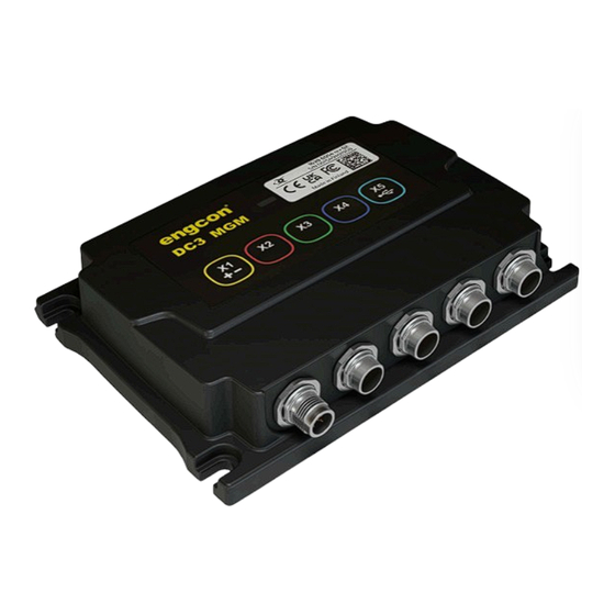
- Page 35 1 x three-colour status indicator Outputs 3 x CAN (X2, X3, X4) 1A 1 x USB (X5) Inputs 1 x CAN (X1) 3A Wireless communication Bluetooth LE 7.1.1. Connector overview DC3 MGM Function Type M12, 5-pin, A-coded male 12/24V (in) CAN-H CAN-L...
- Page 36 7 Technical data X2-X4 Function Type M12, 5-pin, A-coded female 12/24V (ut) CAN-H CAN-L X5: USB Function Type Data - M12, 5-pin, B-coded female USB +5V Data + USB GND OTG UID...
- Page 37 8 Glossary 8. Glossary 8.1. Abbreviations Term Description Base Control Module CAN to CAN Digging Control 3 engcon (Engström Construction) engcon Machine Link engcon Positioning System engcon TechTool Master Gateway Module MIG2 Microprop Grip 2 Q-Safe Light Module Quick hitch Panel Module...
- Page 38 Notes ..................................................................................................................................................................................................................................................................................................................................................................................................................................................................................................................................................................................................................................................
- Page 39 Notes ..................................................................................................................................................................................................................................................................................................................................................................................................................................................................................................................................................................................................................................................
- Page 40 International Box 111, SE-833 21 Strömsund, Sweden +46 (0) 670-178 00, international@engcon.com www.engcon.com...
Need help?
Do you have a question about the DC3 and is the answer not in the manual?
Questions and answers