
Related Manuals for Hotstart DLV


Summary of Contents for Hotstart DLV
- Page 1 216306-000 rev1 INSTALLATION & OPERATION MANUAL D U A L F L U I D C I R C U L AT I N G H E AT I N G S Y S T E M MODEL...
- Page 2 (this page intentionally left blank)
- Page 3 IOM216306-000 IDENTIFYING YOUR SYSTEM The Hotstart heating system is designed to heat fluids for use in marine propulsion, diesel-powered generator sets, locomotives, gas compression or any large-engine applications. Each heating system has an identification plate which includes the part number and serial number.
- Page 4 • Power disconnection: A means to disconnect the heater from the power supply is required. Hotstart recommends that a WARNING power switch or circuit breaker be located near the heater for safety and ease of use. Hazardous voltage: Before wiring, servicing or cleaning the heating system, turn off the power and follow your organization’s lockout and tagout procedure.
-
Page 5: Table Of Contents
SYSTEM COMPONENTS | 5.1.1 Coolant & Oil Install Kit (Optional) | 3.1.1 Motor Protection Switch (MPS) | 5.1.2 DLV Installation Kit Parts List | 3.1.2 High-Limit TCR (Temperature Control Relay) | 3.1.3 Control TCR (Temperature Control Relay) | INTERFACE COMPONENTS | 3.2.1... - Page 6 (this page intentionally left blank) & installation operation manual dlv heating system...
-
Page 7: Overview
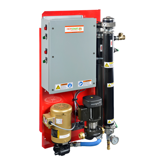
The heating system consists of the following main components: See Figure 1. NOTE: Component illustrations are for reference only and are not to scale. See part drawings for dimensions and specifications. Figure 1. DLV heating system components. Coolant High-Limit RTD (resistance... -
Page 8: Operation Overview
A coolant check valve (included with the DLV unit and installed at the coolant outlet) and an oil check valve (user-supplied and installed near the oil suction port) prevent backflow while the engine is operating. When the engine is shut down, the heating system should be activated locally or remotely to resume maintaining the engine’s optimal starting temperature. -
Page 9: Plumbing Installation
If the pump is installed above the minimum oil level, a check valve must be installed. Isolation valves: Hotstart recommends installing full-flow ball valves to isolate the heating system in order to perform service on the system or engine without draining oil or coolant. -
Page 10: Oil Plumbing
When installing diameter hose; for most installations, Hotstart the DLV oil supply line, refer to the following Hotstart recommends using a hose with a size larger guidelines (see SECTION 5.1 for optional coolant and inner diameter than the pump inlet. -
Page 11: Oil Plumbing Illustration
NOTE: Installation illustrations are for reference only and are not to scale. See part drawings for dimensions and specifications. CHECK VALVE DISCHARGE OIL SUCTION SECTION 2.1.1 PORT PORT SECTION 2.1.2 SECTION 2.1.1 ISOLATION VALVES OIL RETURN SECTION 2.1.2 OIL SUPPLY SECTION 2.1.1 & installation operation manual dlv heating system... -
Page 12: Coolant Plumbing Illustration
NOTE: Installation illustrations are for reference only and are not to scale. See part drawings for dimensions and specifications. COOLANT DISCHARGE PORT SECTION 2.4.2 COOLANT SUCTION PORT SECTION 2.4.1 COOLANT RETURN ISOLATION VALVES SECTION 2.4.2 PRESSURE RELIEF VALVE SECTION 2.4.3 COOLANT SUPPLY SECTION 2.4.1 & installation operation manual dlv heating system... -
Page 13: Coolant Plumbing
Figure 5. Coolant suction port installed at main locomotive engine drain. Note suction port (A) has been installed at the same level as the drain (B), ensuring DLV pump will draw water from the cooling system’s lowest point. 2.4.3 COOLANT PRESSURE RELIEF 2.4.2... -
Page 14: Mounting
NOTE: The specified power source must be within plus or minus 10% of the rated voltage. Figure 7. DLV 0.438 inch (11.13 mm) diameter mounting holes × 6 (A). NOTE: The circuit breaker must be near the Mount unit in orientation shown. -
Page 15: Customer Interface Connections
Figure 9. Main power supply and customer interface connections as shown in the DLV control box. Reference electrical schematic drawing for proper wiring locations; the following illustrations are typical customer interface locations. Main power ground block Oil fault signal Main power terminal block... -
Page 16: High-Limit Tcr (Temperature Control Relay)
TCR4 be switched off and the MPS reset/on button must be pressed. DLV control and high-limit TCRs (right). The standard setting for TCR1 control dial (C) is 122 °F (50 °C). The standard setting for TCR3 control dial (D) is 104 °F (40 °C). -
Page 17: Heating System Start-Up
Turn and hold the switch to prime prime Figure 11. DLV oil pump assembly. Note that the to evacuate any remaining air in the lines. pressure relief valve cap must always point toward the inlet side of pump. Screw is installed on outlet NOTE: When priming the pump, the pressure side of pump. -
Page 18: Maintenance, Repair And Troubleshooting
Magnetic contactors are used as voltage switching or TCR4) will shut down the coolant or oil heating controls for motors and heating elements in Hotstart system, including the pump motor. A fault signal will heating systems. The contactors use 120 volt or 240 be transmitted and the coolant or oil fault light will volt coils. -
Page 19: Motor Lubrication
A volatile corrosion inhibitor (VCI) is provided with each control box and should be replaced once a year. NOTE: Heating systems placed in extended storage will require that the VCI is replaced at six month intervals. See SECTION 4.4. & installation operation manual dlv heating system... -
Page 20: Temperature Control Relay (Tcr)
Figure 12. Control TCRs (TCR1, shock. TCR3) showing terminals T1, T2 and T3. If the DLV heating system does not maintain the desired preset control temperature or signals a high-limit temperature fault immediately upon system start-up, TYPE RTD Position... -
Page 21: Resistance Temperature Device (Rtd)
4.2.11 RESISTANCE TEMPERATURE DEVICE (RTD) WARNING Figure 14. DLV high- Hazardous voltage: Before wiring, servicing or cleaning limit RTDs (A), control the heating system, turn off the power and follow your RTDs (B) and RTD organization’s lockout and tagout procedure. Failure plug detail (C). -
Page 22: 4.2.12 Heating Tank/Element
17. The wattage and phase of the heating element are NOTE: To avoid leaks, HOTSTART recommends listed on the identification plate on the outside of the tightening the V-clamp screw to 15 lbf · ft element (H). -
Page 23: Recommended Maintenance
If long-term storage is necessary, precautions must be HOTSTART recommends running the heating system taken to ensure that the heating system is operational for a minimum of 20 minutes each month. Circulating for start-up. -
Page 24: Troubleshooting
Control TCR set point too low Adjust set point for control TCR. See SECTION 3.1.3. RTD failure Check TCR and RTD. See SECTION 4.2.10. RTD cable failure Check TCR and RTD. See SECTION 4.2.10. & installation operation manual dlv heating system... -
Page 25: Appendix
The following kits are available for DLV installation: 5.1.1 DLV Installation Kit (Optional) This optional kit includes hoses and fittings for DLV oil and coolant plumbing installation. See page 20 and page 21. 5.1.2 DLV Installation Kit Parts List This list contains all parts for the optional DLV installation kit. See page 22. -
Page 26: Coolant & Oil Install Kit (Optional)
& installation operation manual dlv heating system... -
Page 27: Coolant & Oil Install Kit (Optional)
& installation operation manual dlv heating system... -
Page 28: Dlv Installation Kit Parts List
PRP218027-001 TEE, .75 X .75 X .75 BLK PRP218117-005 ADAPTER 90 .75MPT X 20MJI C PRP127018-004 HOSE, #20 FJIC X 224 OAL PRP215175-001 CLAMP #20 HOSE Table 3. DLV Installation Kit parts list. & installation operation manual dlv heating system...
Need help?
Do you have a question about the DLV and is the answer not in the manual?
Questions and answers