
Related Manuals for Hotstart DLV


Summary of Contents for Hotstart DLV
- Page 1 216306-000 rev0 INSTALLATION & OPERATION MANUAL D U A L F L U I D C I R C U L AT I N G H E AT I N G S Y S T E M MODEL...
-
Page 3: Identifying Your System
IDENTIFYING YOUR SYSTEM IOM216306-000 The HOTSTART heating system is designed to heat fluids for use in marine propulsion, diesel-powered generator sets, locomotives, gas compression or any large-engine applications. The system is pre-wired, pre-plumbed and assembled on steel plate. Each heating system has an identification plate which includes the part number and serial number. -
Page 4: Important Safety Information
Overcurrent limiting: The power supply must be protected by a suitable overcurrent limiting device. • Power disconnection: A means to disconnect the heater from the power supply is required. HOTSTART recommends that a power switch or circuit breaker be located near the heater for safety and ease of use. & installation... -
Page 5: Table Of Contents
COOLANT PLUMBING ILLUSTRATION | MOUNTING | 2.5.1 Tank and Pump | MAIN POWER SUPPLY | CUSTOMER INTERFACE CONNECTIONS | SYSTEM COMPONENTS AND OPERATION | ON/OFF/PRIME SWITCH | MOTOR PROTECTION SWITCH (MPS) | PRESSURE/TEMPERATURE GAUGES | & installation operation manual dlv heating system... - Page 6 Volatile Corrosion Inhibitor (VCI) | 5.2.11 Temperature Control Relay (TCR) | 5.2.12 Resistance Temperature Device (RTD) | 5.2.13 Heating Tank/Element | 5.2.14 Reassembly of Heating Element and Tank | RECOMMENDED MAINTENANCE | STORAGE REQUIREMENTS | TROUBLESHOOTING | & installation operation manual dlv heating system...
-
Page 7: Overview
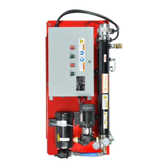
OVERVIEW HEATING SYSTEM COMPONENTS The DLV heating system consists of the following main components: See Fig. 1. OOE: Component illustrations are for reference only and are not to scale. See part drawings for dimensions and specifications. Figure 1. DLV heating system components. -
Page 8: Operation Overview
A coolant check valve (included with the DLV unit and installed at the coolant outlet) and an oil check valve (user-supplied and installed near the oil suction port) prevent backflow while the engine is operating. When the engine is shut down, the heating system should be activated locally or remotely to resume maintaining the engine’s optimal starting temperature. -
Page 9: Plumbing Installation
If the pump is installed above the minimum oil level, a check valve must be installed. Isolation valves: HOTSTART recommends installing full-flow ball valves to isolate the heating system in order to perform service on the system or engine without draining oil or coolant. -
Page 10: Oil Plumbing Installation
2.1.1 OIL SUPPLY Installing a short, straight oil supply line with a minimum of flow restriction is the most important step toward ensuring heating system longevity. When installing the DLV oil supply line, refer to the following HOTSTART guidelines: •... -
Page 11: Oil Plumbing Illustration
OOE: Installation illustrations are for reference only and are not to scale. See part drawings for dimensions and specifications. CHECK VALVE OIL SUCTION PORT SECOIO 2.1.1 SECOIO 2.1.1 OIL RETURN SECOIO 2.1.2 DISCHARGE PORT SECOIO 2.1.2 ISOLATION VALVE ISOLATION VALVE OIL SUPPLY SECOIO 2.1.1 & installation operation manual dlv heating system... -
Page 12: Coolant Plumbing Installation
OOE: To maximize flow and allow the longest possible supply line, install the largest practical inner diameter hose; for most installations, HOTSTART recommends using a hose with a size larger inner diameter than the pump inlet. • Install the coolant suction port as low as possible on the engine’s water jacket, typically near the main water drain. -
Page 13: Coolant Plumbing Illustration
OOE: Installation illustrations are for reference only and are not to scale. See part drawings for PORT dimensions and specifications. SECOIO 2.3.2 COOLANT SUCTION PORT SECOIO 2.3.1 ISOLATION VALVE COOLANT RETURN ISOLATION SECOIO 2.3.2 VALVE PRESSURE RELIEF VALVE SECOIO 2.3.3 COOLANT SUPPLY SECOIO 2.3.1 & installation operation manual dlv heating system... -
Page 14: Mounting
Mount the heater in a vertical orientation with pumps directly below the control box. Reference drawings for mounting position. When installing the heating system, note that the tanks requires a minimum of 30 inches (63.5 cm) of clearance to remove each element for maintenance. See SECOIO 5.1.13. & installation operation manual dlv heating system... -
Page 15: Main Power Supply
OOE: The specified power source must be within plus or minus 10% of the rated voltage. OOE: The circuit breaker must be near the heating system and easily accessible. HOTSTART recommends connecting the heating system to a circuit breaker rated for 125% of the system’s maximum load. -
Page 16: Customer Interface Connections
OOE: The 24 V dc shutdown connection is wired C (normally closed) from the factory; see system wiring schematic for directions to switch to NO (normally open) operation. Figure 3. Customer interface connection TB2:1 TB2:2 COOLANT FAULT, FAULT WHEN CLOSED wiring schematic for the DLV heating system. TB2:3 TB2:4 COOLANT PUMP MOTOR TB2:5 TB2:6... -
Page 17: System Components And Operation
Figure 5. Motor protection switches MPS1 (coolant) and MPS2 (oil). To reset the MPS, the heating RESET / ON system must be switched off and the reset/on button must be pressed. STOP / OFF & installation operation manual dlv heating system... -
Page 18: Pressure/Temperature Gauges
PRESSURE/TEMPERATURE GAUGES The DLV model features a temperature/pressure gauge mounted at the inlet of each heating tank. The gauges will indicate a pressure increase when the pump motor is engaged by holding the prime switch to or during normal operation. The gauges will also indicate the current temperature of the prime respective fluid. -
Page 19: Heating System Start-Up
Turn the control dials on the temperature control relay TCR3 to the desired temperature setting for engine oil. HOTSTART recommends a control temperature on TCR3 of 104 °F (40 °C). The high-limit temperature setting on TCR4 should be set at 194 °F (90 °C). See SECOIO 3.5 and SECOIO... -
Page 20: Maintenance, Repair And Troubleshooting
5.2.2 ELECTRICAL CONNECTIONS Vibration may cause terminals to loosen. At start-up, tighten electrical connections. Check connections again in a week. Tighten all electrical connections every three months. & installation operation manual dlv heating system... -
Page 21: System Mounting
5.2.4 MAGNETIC CONTACTORS Magnetic contactors are used as voltage switching controls for motors and heating elements in HOTSTART heating systems. The contactors use 120 volt or 240 volt coils. To test for failure, check for continuity across the coil connections; an open or direct-short reading indicates a failed contactor coil. -
Page 22: Temperature Control Relay (Tcr)
Failure to do so could allow others to turn on the power unexpectedly, resulting in harmful or fatal electrical shock. If the DLV heating system does not maintain the desired preset control temperature or consistently signals a high-limit temperature fault, the TCR (temperature control relay) , the RTD (resistance temperature device), or the RTD cable may require replacement. -
Page 23: Resistance Temperature Device (Rtd)
Refer to SECOIO 4 for system start-up procedures. Figure 11. RTDs shown removed from tank assemblies. Figure 12. Proper RTD orientation. Note the notch centered at the top of the RTD connection. & installation operation manual dlv heating system... -
Page 24: 5.2.13 Heating Tank/Element
To reassemble the heating element and tank, follow the steps listed in SECOIO 5.2.13 in reverse order. Make sure the ground and power electrical wires are properly reconnected using the provided washers, cup washers and nuts. & installation operation manual dlv heating system... - Page 25 Unscrew to remove element wiring. (3 PHASE DELTA) (3 PHASE WYE) (1 PHASE PARALLEL) (1 PHASE SERIES) Figure 15. Heating tank element phase configurations. Replacement elements may be a different phase configuration. & installation operation manual dlv heating system...
-
Page 26: Recommended Maintenance
During the offseason, or during periods in which the heating system is not active for a month or longer, HOTSTART recommends running the heating system for a minimum of 20 minutes each month. Circulating and heating fluid at regular intervals will reduce pump seal wear and promote pump seal longevity. -
Page 27: Troubleshooting
Control TCR set point too low Adjust set point for control TCR. See SECOIO 3.6. Check TCR and RTD. See SECOIO RTD failure 5.2.11 Check TCR and RTD. See SECOIO RTD cable failure 5.2.11. & installation operation manual dlv heating system...
Need help?
Do you have a question about the DLV and is the answer not in the manual?
Questions and answers