
Related Manuals for Hotstart CMM


Summary of Contents for Hotstart CMM
- Page 1 216383-000 rev0 INSTALLATION & OPERATION MANUAL C O O L A N T C I R C U L AT I N G H E AT I N G S Y S T E M MODEL...
- Page 3 IDENTIFYING YOUR SYSTEM IOM216383-000 The Hotstart heating system is designed to heat fluids for use in marine propulsion, diesel-powered generator sets, locomotives, gas compression, heavy equipment or other large-engine applications. Each heating system has an identification plate which includes the part number and serial number.
- Page 4 IMPORTANT SAFETY Power disconnection: A means to disconnect the heating system from the power supply is required. INFORMATION HOTSTART recommends that a power switch or circuit breaker be located near the heating system for safety and ease of use. DANGER...
-
Page 5: Table Of Contents
TABLE OF CONTENTS OVERVIEW | 4.2.3 System Mounting | 4.2.4 System Draining | HEATING SYSTEM COMPONENTS | 4.2.5 Magnetic Contactors | 4.2.6 Pump Seal | OPERATION OVERVIEW | 4.2.7 Pressure Relief Valve | INSTALLATION | 4.2.8 Pressure/ Temperature Gauge | 4.2.9 Volatile Corrosion Inhibitor | COOLANT PLUMBING INSTALLATION |... - Page 6 & installation operation manual clm heating system...
-
Page 7: Overview
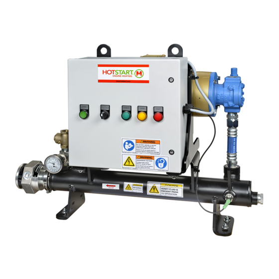
HEATING SYSTEM COMPONENTS NOTE: Component illustrations are for reference only and are not to scale. See part drawings for dimensions and specifications. Figure 1. Typical CMM/CLM system components. Model style and configuration may vary. See part drawings for dimensions and specifications. -
Page 8: Operation Overview
A coolant check valve (included with the CMM/CLM unit and installed at the coolant outlet) prevents backflow while the engine is operating. When the engine is shut down, the heating system should be activated locally or remotely to resume maintaining the engine’s optimal starting temperature. -
Page 9: Installation
Pump seal damage: Do not reduce the coolant supply line to an inner diameter smaller than the pump inlet; pump seal damage will occur. Isolation valves: Hotstart recommends installing full-flow ball valves to isolate the heating system in order to perform service on the system or engine without draining coolant. -
Page 10: Coolant Plumbing Installation
COOLANT PLUMBING 2.1.2 COOLANT RETURN INSTALLATION When installing the CMM/CLM coolant return line, refer to the following Hotstart guidelines (See SECTION 2.2): NOTICE • Size the coolant return line per the coolant Heating system damage: Engine vibration will outlet. NOTICE! Do not reduce the return damage the heating system;... -
Page 11: Coolant Plumbing Illustration
COOLANT PLUMBING ILLUSTRATION COOLANT COOLANT SUCTION PORT DISCHARGE PORT SECTION 2.1.1 SECTION 2.1.2 COOLANT RETURN SECTION 2.1.2 ISOLATION VALVE ISOLATION VALVE COOLANT SUPPLY SECTION 2.1.1 COOLANT PRESSURE RELIEF VALVE SECTION 2.1.3 & installation operation manual clm heating system... -
Page 12: Mounting
Heating systems with flanges have marked lift points. When lifting, use soft straps and avoid placing side-loads on heating system plumbing Figure 5. CMM/CLM 0.75 inch (19.05 mm) and .38 inch (9.65 mm) components, including fluid pumps. diameter mounting holes × 4 (A). -
Page 13: Customer Interface Connections
Figure 7. Main power supply and customer interface connections as Main power ground block Coolant motor run signal TCR1:T1 TCR1:T2 shown in the CMM/CLM control box. Reference electrical schematic Main power terminal block Remote On/Off drawing for proper wiring locations; the following illustrations are TCR1:T3... -
Page 14: Components And Operation
The following is an operational description for each of The motor protection switch (MPS1) protects the pump the CMM/CLM interface and system components. motor from overloads. The MPS will be set at the full load amperage of the motor when shipped from the factory. -
Page 15: Heating System Start-Up
Figure 8. CMM/CLM motor protection switch (left), showing reset/ on (A) and (B) stop/off buttons. To reset the MPS, the heating system must be switched off and the MPS reset/on button must be pressed. CLM/CMM control TCR and high-limit TCR (above). The standard setting for TCR1 coolant control dial (C) is 50 °C (122 °F). -
Page 16: Maintenance And Troubleshooting
The pump motor protection switch is tripped (MPS1). • The high-limit temperature is exceeded (TCR2). Figure 9. CMM/CLM pump bleed screw (A). Unscrew bleed screw to SYSTEM MAINTENANCE vent trapped air. Tighten screw once coolant begins to vent. 4.2.1 PLUMBING CONNECTIONS... -
Page 17: System Draining
No maintenance for this part is required. 4.2.9 VOLATILE CORROSION INHIBITOR Figure 10. CMM/CLM, showing drain plug (A) at coolant tank. A volatile corrosion inhibitor (VCI) is provided with each 4.2.5 MAGNETIC CONTACTORS control box and should be replaced once a year. -
Page 18: Temperature Control Relay (Tcr)
TCRs (TCR1 and TCR2) shock. showing terminals T1, T2 and If the CMM/CLM heating system does not maintain the desired preset control temperature or signals a high-limit temperature fault immediately upon system start-up, TYPE... - Page 19 (RTD), use the following procedures. NOTE: Before removing and replacing an RTD, ensure the RTD is malfunctioning. See SECTION 4.2.10. Figure 13. CMM/CLM control RTD (A), high-limit RTD (B), and plug detail De-energize the heating system. Allow fluid to cool.
-
Page 20: 4.2.12 Heating Tank/Element
(E). See SECTION 4.2.4. NOTE: System wattage may be changed by replacing the element assembly. Prior to changing wattage, contact Hotstart with your system’s Remove the cap (A) from the heating element part number and serial number to ensure it is service entrance enclosure. -
Page 21: Recommended Maintenance
RECOMMENDED MAINTENANCE INTERVAL MAINTENANCE TASK Tighten electrical connections. See SECTION 4.2.2. At initial start-up One week after initial start-up Check and tighten electrical connections. See SECTION 4.2.2. Every three months Tighten electrical connections. Annually Drain, clean and flush heating system. Check for cracked or weakened hoses and replace if necessary. -
Page 22: Troubleshooting
Pump motor turning Reverse any two power leads (in three-phase system). Restart system. See SECTION 3.3.1. For single-phase backwards systems, contact Hotstart. Control TCR failure: closed Check and replace if necessary. See SECTION 4.2.10. Motor failure Check and replace if necessary. Restart system.
Need help?
Do you have a question about the CMM and is the answer not in the manual?
Questions and answers