Table of Contents
Advertisement
Quick Links
Instructions – Parts List
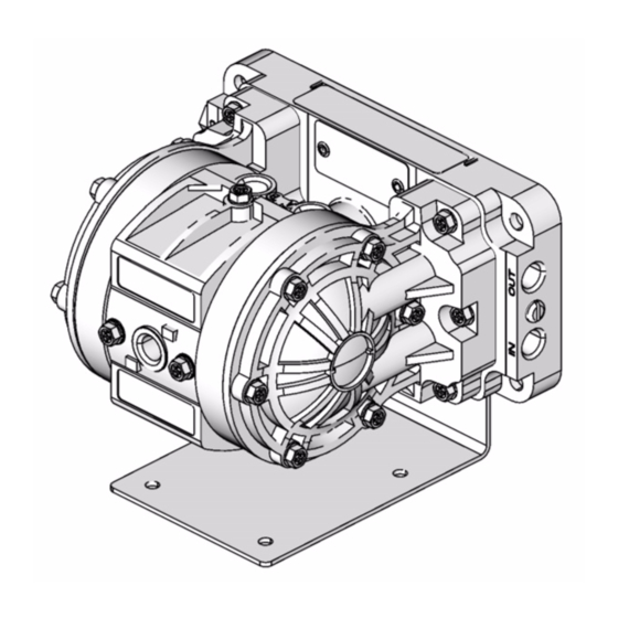
Husky ™ 205 Air-Operated
Diaphragm Pumps
100 psi (0.7 MPa, 7 bar) Maximum Incoming Air Pressure
100 psi (0.7 MPa, 7 bar) Maximum Fluid Working Pressure
Important Safety Instructions.
Read all warnings and instructions in this manual.
Save these instructions.
Part No. D120XX
Polypropylene Pump with Air-Operated Motor
Part No. D110XX* and DM10XX*
Acetal Pump with Air-Operated Motor
Part No. D150XX and DM50XX
PVDF Pump with Air-Operated Motor
Part No. D220XX
Polypropylene Pump with Solenoid Ports
Part No. D210XX*
Acetal Pump with Solenoid Ports
Part No. D250XX
PVDF Pump with Solenoid Ports
*
These models are certified:
II 2 GD
Ex h IIC 66°C...135°C Gb
Ex h IIIC T135°C Db
ATEX T-code rating is dependent on the temperature
of the fluid being pumped. Fluid temperature is limited
by the materials of the pump interior wetted parts.
See Technical Data for the maximum fluid operating
temperature for your specific pump model.
www.northridgepumps.com
308652ZAM
EN
ti10660a
Advertisement
Chapters
Table of Contents

Related Manuals for Graco Husky 205 D110 Series


Summary of Contents for Graco Husky 205 D110 Series
- Page 1 Instructions – Parts List Husky ™ 205 Air-Operated 308652ZAM Diaphragm Pumps 100 psi (0.7 MPa, 7 bar) Maximum Incoming Air Pressure 100 psi (0.7 MPa, 7 bar) Maximum Fluid Working Pressure Important Safety Instructions. Read all warnings and instructions in this manual. Save these instructions.
-
Page 2: Table Of Contents
Graco Standard Warranty..... 24 Graco Information......24... - Page 3 WARNING HAZARDOUS FLUIDS Improper handling of hazardous fluids or inhaling toxic vapors can cause extremely serious injury or death from splashing in the eyes, ingestion, or bodily contamination. Observe all the following precautions when you handle hazardous or potentially hazardous fluids. •...
-
Page 4: Installation
Installation Tightening Threaded Fasteners Before First Acetal Pump Grounding Instructions For polypropylene and PVDF pumps, see the warning above. Before using the pump for the first time, check and Ground all of this equipment. retorque all external fasteners. See Torque Sequence, page 18. - Page 5 Installation Air Exhaust Ventilation WARNING TOXIC FLUID HAZARD Read the HAZARDOUS FLUIDS and FIRE AND EXPLOSION HAZARD sections on page 3 before you operate this pump. Be sure the system is properly ventilated for your type of installation. You must vent the exhaust to a safe place, away from people, animals or food handling areas when pumping flammable or...
- Page 6 Valve and Fluid Drain Valve warning above. designs. Locate another bleed-type master air valve upstream from all air line accessories, and use it Typical installation includes (not supplied by Graco): to isolate the accessories during cleaning and • For solenoid operation: a four-way, 5-port, 3-position repair.
- Page 7 Installation Husky 205 pump Bleed-type master air valve (required for pump) Air line(s) Master air valve (for accessories) Air line filter Muffler Pump air regulator Fluid drain valve (required on fluid outlet side of pump) Fluid suction line Fluid supply hose Internal Air Valve View Bung adapter (shown upright for clarity)
-
Page 8: Operation
Operation Pressure Relief Procedure 3. Place the suction tube (if used) in the fluid to be pumped. WARNING 4. Place the end of the outlet hose into an appropriate container. To reduce the risk of serious injury, including splashing fluid in the eyes or on the skin, follow this 5. -
Page 9: Maintenance
Maintenance Lubrication Flushing and Storage The air valve is lubricated at the factory and designed to Flush the pump to prevent the fluid from drying or operate without additional lubrication. freezing in the pump and damaging it. Always flush the pump and relieve the pressure before storing for any If added lubrication is desired, every 500 hours of length of time. -
Page 10: Troubleshooting
Troubleshooting Relieve the pressure before you check or service the WARNING equipment. To reduce the risk of serious injury whenever you are Check all possible problems and causes before you instructed to relieve pressure, always follow the disassemble the pump. Pressure Relief Procedure on page 8. - Page 11 Troubleshooting Internal Air Valve-Operated Pumps Only PROBLEM CAUSE SOLUTION The pump will not cycle, or it cycles The air valve is stuck or dirty. Disassemble and clean or repair the once and stops. air valve. See page 12. Use filtered air. Not enough air pressure supplied.
-
Page 12: Service
Service Service Kits 2. Remove the four screws (14) that hold the valve cover (7) on the center housing (1). Service Kits may be ordered separately. 3. Remove the valve block (4) and valve carriage (2), To repair the air valve, order Part No. 238853. Parts and replace the u-cups (3). - Page 13 Service Replacing Diaphragms Replace the diaphragms as follows. See F . 6 and F . 7. 1. Relieve the pressure, and disconnect the air line 5. Remove the diaphragm pins (8), remove and replace from the pump. the o-rings (9), and reinstall the diaphragm pins in the center housing (1).
- Page 14 Service Replacing Check Valves Replace each pair of check valves as follows. See F . 7. 3. Remove and replace the check valves (20), being careful to orient each check valve exactly like the 1. Relieve the pressure, and disconnect the air line one it is replacing.
-
Page 15: Parts Matrix
Parts Matrix Husky 205 Polypropylene, Acetal*, and PVDF Pumps The Model Number of your pump is marked on the pump’s serial plate. To determine the Model Number of your pump from the following matrix, select the six digits that describe your pump, working from left to right. The first digit is always D, designating Husky diaphragm pumps. -
Page 16: Parts
Parts Air Motor Section (matrix column 2) 191140 COVER, valve 290229 LABEL, warning Ref. 191141 PLATE, diaphragm; Digit Part No. Description Qty. polypropylene 240898 HOUSING, center, assembly COVER, fluid; polypropylene 2 (includes 12 and 57) 276473 Pump series A to E 191157 CARRIAGE, valve 278943... - Page 17 Parts Diaphragm (matrix column 6) Digit Ref. Part No. Description Qty. 191402 DIAPHRAGM; PTFE † (for all Husky 205 pumps) 196385 DIAPHRAGM; † Santoprene 20† * 17 * 16 30† ti10666c Used on acetal models only. Torque to 45-47 in-lb (5.0-5.3 Nm). See Torque Sequence on page 18 Lips of u-cups (3) must face toward each other, toward center of valve carriage (2).
-
Page 18: Torque Sequence
Torque Sequence For proper installation, always follow torque sequence whenever you are instructed to torque screws. 1. Valve Cover 2. Left/Right Fluid Cover Torque bolts to 45-47 in-lb (5.0-5.3 Nm) Torque bolts to 42-47 in-lb (4.7-5.3 Nm) 3. Manifold to Center Section Torque bolts to 42-47 in-lb (4.7-5.3 Nm) 11, 19 12, 20... -
Page 19: Technical Data
Technical Data Maximum fluid working pressure ... . . 100 psi Weight (0.7 MPa, 7 bar) Polypropylene pump ....2.0 lb (0.9 kg) Maximum/minimum air pressure . -
Page 20: Dimensions And Mounting Hole Layout
Dimensions and Mounting Hole Layout 6.0 in. 152.4 mm 3.7 in. 94 mm 5.4 in. 137 mm ti10913a Four 0.175 in. x .85 in. deep 3.0 in. 4.445 mm x 21.59 mm deep 76.2 mm diameter holes Four 0.281 in. 7.137 mm diameter holes 2.5 in. -
Page 21: Performance Charts
Performance Charts Husky 205 Fluid Outlet Pressure Test Conditions: Pump tested in water with inlet submerged. Fluid Pressure Curves at 100 psi (0.7 MPa, 7 bar) air pressure at 70 psi (0.48 MPa, 4.8 bar) air pressure at 40 psi (0.28 MPa, 2.8 bar) air pressure FLUID FLOW--gpm (lpm) To find Fluid Outlet Pressure (psi/MPa/bar) at a specific fluid flow (gpm/lpm) and operating air pressure... -
Page 22: At 70 Psi (0.49 Mpa, 4.9 Bar)
Performance Charts Husky 205 Air Consumption Test Conditions: Pump tested in water with inlet submerged. Air Consumption Curves at 100 psi (0.7 MPa, 7 bar) air pressure at 70 psi (0.48 MPa, 4.8 bar) air pressure at 40 psi (0.28 MPa, 2.8 bar) air pressure FLUID FLOW--gpm (lpm) To find Pump Air Consumption (scfm or m /min) at a... - Page 23 Notes 308652ZAM www.northridgepumps.com...
-
Page 24: Graco Standard Warranty
With the exception of any special, extended, or limited warranty published by Graco, Graco will, for a period of twelve months from the date of sale, repair or replace any part of the equipment determined by Graco to be defective.
Need help?
Do you have a question about the Husky 205 D110 Series and is the answer not in the manual?
Questions and answers