Table of Contents
Advertisement
Quick Links
Advertisement
Table of Contents

Related Manuals for LG FLATRON L181S


Summary of Contents for LG FLATRON L181S
- Page 1 Website:http://biz.LGservice.com E-mail:http://www.LGEservice.com/techsup.html COLOR MONITOR SERVICE MANUAL CHASSIS NO. : CL-43 MODEL: L1811S (L1811SL-AL**R) ) **Same model for Service CAUTION BEFORE SERVICING THE UNIT, READ THE SAFETY PRECAUTIONS IN THIS MANUAL. L1811S *To apply the Mstar Chip.
-
Page 2: Table Of Contents
CONTENTS SPECIFICATIONS ........... 2 ADJUSTMENT ............10 PRECAUTIONS ............3 TROUBLESHOOTING GUIDE ......11 TIMING CHART ............4 PRINTED CIRCUIT BOARD........14 OPERATING INSTRUCTIONS ........ 5 EXPLODED VIEW...........17 WIRING DIAGRAM ..........6 REPLACEMENT PARTS LIST .......19 BLOCK DIAGRAM ........... 7 PIN CONFIGURATION ...........22 DESCRIPTION OF BLOCK DIAGRAM.....8 SCHEMATIC DIAGRAM ......... -
Page 3: Precautions
PRECAUTION WARNING FOR THE SAFETY-RELATED COMPONENT. WARNING BE CAREFUL ELECTRIC SHOCK ! • There are some special components used in LCD monitor that are important for safety. These parts are • If you want to replace with the new backlight (CCFL) or marked on the schematic diagram and the inverter circuit, must disconnect the AC adapter... -
Page 4: Timing Chart
TIMING CHART VIDEO SYNC << Dot Clock (MHz), Horizontal Frequency (kHz), Vertical Frequency (Hz), Horizontal etc... (µs), Vertical etc... (ms) >> Total Period Video Active Time Front Porch Sync Duration Back Porch Sync Mode Resolution Frequency Clock Polarity Sort 31.469 640x350 25.175 70Hz... -
Page 5: Operating Instructions
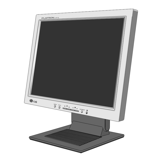
OPERATING INSTRUCTIONS FRONT VIEW REAR VIEW L1811S Power Connect D-Sub Signal See Front Control Panel Connect Front Control Panel 1. Power ON/OFF Button 5. AUTO/SELECT Button Use this button to turn the monitor on or off. Use this button to enter a selection in the On Screen Display. When adjusting your display settings, 2. -
Page 6: Wiring Diagram
OPERATING INSTRUCTIONS CONTROLS LOCKED/UNLOCKED : MENU and This function allows you to secure the current control settings, so that they cannot be inadvertently changed. Press and hold the MENU button and button for 3 seconds: the message “CONTROLS LOCKED” appears. You can unlock the OSD controls at any time by pushing the MENU button and button for 3 seconds: the message “CONTROLS UNLOCKED”... -
Page 7: Block Diagram
BLOCK DIAGRAM - 7 -... -
Page 8: Description Of Block Diagram
DESCRIPTION OF BLOCK DIAGRAM 1. Video Controller Part & Display Data Transmitter Part.(MST9111) This part amplifies the level of video signal for the digital conversion and converts from the analog video signal to the digital video signal using a pixel clock. The pixel clock for each mode is generated by the PLL. - Page 9 Power Board Block Diagram 50 ~ 60Hz 100KHz HVDC INPUT RECTIFIER ENERGY OUTPUT RECTIFIER COMPONENTS AND FILTER TRANSFER AND FILTER LINE 100 ~ 240V SIGNAL PWM CONTROL PHOTO -COUPLER COLLECT- CIRCUIT ISOLATION PRIMARY SECONDARY High Voltage output INVERTER CIRCUIT Operation description_Power 1.
-
Page 10: Adjustment
ADJUSTMENT All adjustment are thoroughly checked and corrected when the monitor leaves the factory, but sometimes several minor adjustment may be required. Adjustment should be following procedure and after warming up for a minimum of 10 minutes. • Alignment appliances and tools. - IBM compatible PC - Programmable Signal Generator. -
Page 11: Troubleshooting Guide
TROUBLESHOOTING GUIDE 1. NO POWER NO POWER (POWER INDICATOR OFF) CHECK POWER BOARD, AND FIND CHECK J709 OUT A SHORT POINT VOLTAGE PIN5, PIN6 (5V)? AS OPENING EACH POWER LINE CHECK U803 PIN 3 CHECK U803. VOLTAGE (5V) ? CHECK CHECK 5VS LINE U804 PIN 3 Voltage (OPEN CHECK) - Page 12 2. NO RASTER (OSD IS NOT DISPLAYED) – LIPS NO RASTER (OSD IS NOT DISPLAYED) J709 PIN5, PIN 6 CHECK LIPS CHECK MICOM INV J707 PIN8 ON/OFF PORT. 12V? 1. CONFIRM BRIGHTNESS OSD CONTRL STATE. J707 PIN7 2. CHECK MICOM DIM-ADJ PORT CHECK PULSE AS...
- Page 13 3. NO RASTER (OSD IS NOT DISPLAYED) – MST9111 NO RASTER (OSD IS NOT DISPLAYED) U201 POWER PINS CHECK U804 3.3V? 1. CHECK PIN122, 123 U201 SOLDERING CONDITION PIN122, 123 OSCILLATE AS 2. CHECK X501 12MHZ? 3. TROUBLE IN U201 U501 PIN41 IS 64KHz H-SYNC? CHECK CONNECTION LINE...
- Page 14 4. TROUBLE IN DPM TROUBLE IN DPM CHECK CHECK PC R734, R741 PC IS NOT GOING (SYNC) ? INTO DPM OFF MODE CHECK U501 PIN 11,12 TROUBLE IN WAVEFORM X501 (12MHz) ? CHECK TROUBLE IN U501 PIN 24 SIGNAL CABLE (0V) ? TROUBLE IN PC - 14 -...
-
Page 15: Printed Circuit Board
PRINTED CIRCUIT BOARD 1. MAIN BOARD (Component Side) C708 C709 C711 Q507 Q508 R529 R528 R708 R709 R581 R580 R747 C516 R571 R570 R748 C710 R537 R562 R560 Q704 R533 J706 R711 R534 R552 R766 R710 R539 R559 R513 C550 R762 R550 C514... - Page 16 2. POWER BOARD (Component Side) 3. POWER BOARD (Solder Side) 4. CONTROL BOARD LED1 INPUT MENU DOWN LEFT RIGHT SET/AUTO POWER - 16 -...
-
Page 17: Exploded View
EXPLODED VIEW - 17 -... - Page 18 Ref. No. Part No. CABINET ASSEMBLY, L1811SL BRAND , ANALOG ONLY 3091TKL044P LCD(LIQUID CRYSTAL DISPLAY), LM181E06-A4M1 LG PHILPS TFT COLOR SXGA 18.1" LVDS SMM 6304FLP034A LCD(LIQUID CRYSTAL DISPLAY), LM181E06-A4C3 LG PHILPS TFT COLOR SXGA LVDS SMM or 6304FLP044A BACK COVER ASSEMBLY, LB801G , L1811SG (ANALOG ONLY)
-
Page 19: Replacement Parts List
REPLACEMENT PARTS LIST CAUTION: BEFORE REPLACING ANY OF THESE COMPONENTS, READ CAREFULLY THE SAFETY PRECAUTIONS IN THIS MANUAL. * NOTE SAFETY Mark AL ALTERNATIVE PARTS DATE: 2003. 3. 8. DATE: 2003. 3. 8. *S *AL LOC. NO. PART NO. DESCRIPTION / SPECIFICATION *S *AL LOC. - Page 20 DATE: 2003. 3. 8. DATE: 2003. 3. 8. *S *AL LOC. NO. PART NO. DESCRIPTION / SPECIFICATION *S *AL LOC. NO. PART NO. DESCRIPTION / SPECIFICATION R202 0RJ0682D677 68 OHM 1/10 W 5% 1608 R/TP R733 0RJ1001D677 1K OHM 1/10 W 5% 1608 R/TP R203 0RJ0682D677 68 OHM 1/10 W 5% 1608 R/TP...
- Page 21 DATE: 2003. 3. 8. *S *AL LOC. NO. PART NO. DESCRIPTION / SPECIFICATION 430-858C AFC-520 BAE EUN TA IC901 0IPMGIH001A “ICE2AS01 INFINEON 8P,DIP ST O” IC904 0ISS431000A KA431AZ (LM431AZ) IC905 0ISS780500F KA7805 L901 150-A85F “LX31 GET BAR CHOKE,3.3UH,LB88” L902 150-A85F “LX31 GET BAR CHOKE,3.3UH,LB88”...
-
Page 22: Pin Configuration
PIN CONFIGURATION MST9111 DUAL MSTAR 128P PIN DIAGRAM AVSS_PLL AVSS Pin 1 AVSS LVB0M LVB0P AVDD GNDP VDDP LVB1M AVSS LVB1P LVB2M LVB2P AVDD LVBCKM REXT LVBCKP AVDD_PLL LVB3M AVSS_PLL LVB3P AVDD VDDC AVSS GNDC GNDP VDDP LVA0M LVA0P LVA1M LVA1P LVA2M BIN0M... - Page 23 CAT24WC08J-TE13 8P BLOCK DIAGRAM DIP Package(p) SOIX Package(J) EXTERNAL LOAD V CC V CC SENSE AMPS D OUT SHIFT REGISTERS V SS V SS V CC COLUMN V SS WORD ADDRESS DECODERS BUFFERS TSSOP Package(U) START/STOP LOGIC V CC E PROM XDEC V SS CONTROL...
-
Page 24: Schematic Diagram
SCHEMATIC DIAGRAM 1. SCALER - 24 -... - Page 25 2. MICOM - 25 -...
- Page 26 3. POWER - 26 -...
- Page 27 4. CONNECTOR/JACKS - 27 -...
- Page 28 5. KEY PART - 28 -...
- Page 29 6. POWER - 29 -...
- Page 30 Mar. 2003 P/NO : 3828TSL082L Printed in Korea...
Need help?
Do you have a question about the FLATRON L181S and is the answer not in the manual?
Questions and answers