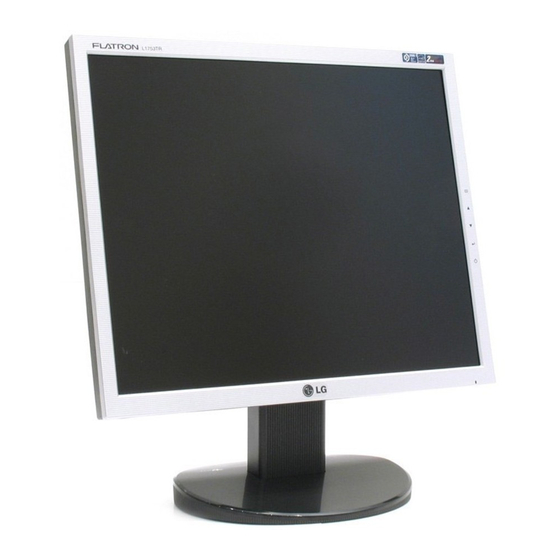
Summarization of Contents
SPECIFICATIONS
LCD CHARACTERISTICS
Details about the LCD module type, size, color depth, and interface.
OPTICAL CHARACTERISTICS
Viewing angle, luminance, and contrast ratio specifications for the monitor.
SIGNAL
Information on sync signals and video input signal characteristics.
MAX RESOLUTION
Specifies the maximum display resolutions supported via D-sub and Digital interfaces.
POWER SUPPLY
Details on power input voltage and power consumption in different modes.
ENVIRONMENT
Specifies operating temperature, humidity, and MTBF for the monitor.
DIMENSIONS
Provides the physical dimensions (width, depth, height) for different models.
WEIGHT
Lists the net and gross weight for different monitor models.
SAFETY PRECAUTIONS
SAFETY-RELATED COMPONENTS
Highlights safety components and the need for manufacturer-specified replacement parts.
HANDLING LCD MODULE
Provides guidelines for safely handling the LCD module and its components.
ELECTRIC SHOCK HAZARD
Warns about electric shock hazards, especially with the inverter circuit.
LEAKAGE CURRENT TEST
Illustrates a circuit diagram for checking leakage current.
SERVICING PRECAUTIONS
GENERAL SERVICING GUIDELINES
General guidelines for safe servicing, including power disconnection and high voltage.
ESD DEVICES HANDLING
Precautions for handling sensitive components to prevent static discharge damage.
REPAIR PROCEDURES
SOLDERING GUIDELINES
Provides best practices for soldering, including tool usage and tip maintenance.
COMPONENT REPLACEMENT
Step-by-step guides for removing and replacing various components like ICs, transistors, and diodes.
CIRCUIT BOARD REPAIR
IC CONNECTION REPAIR
Procedure for repairing copper patterns at IC connections using jumper wires.
OTHER CONNECTION REPAIR
Method for repairing defective copper patterns at non-IC connections with jumper wires.
BLOCK DIAGRAM DESCRIPTIONS
VIDEO CONTROLLER PART
Explains the function of the video controller, including scaler and signal conversion.
POWER PART
Describes the power supply section, regulators, and the inverter's role.
MICOM PART
Details the MICOM part, including EEPROM, control data, and sync signal processing.
LIPS BOARD DIAGRAM
EMI COMPONENTS
Explains the function of EMI components in meeting marketing standards.
INPUT RECTIFIER AND FILTER
Describes the function of the input rectifier and filter for AC to DC conversion.
ENERGY TRANSFER
Explains the role of the power transformer in energy transfer.
OUTPUT RECTIFIER AND FILTER
Details the function of the output rectifier and filter for DC output stabilization.
PHOTO-COUPLER ISOLATION
Describes the function of photo-coupler isolation for stabilized DC output voltage.
SIGNAL COLLECTION
Explains how signal collection feeds back DC output changes to the primary.
ADJUSTMENT
EDID SOFTWARE OPERATION
Guide on using EDID software for port setup and data reading/writing.
SERVICE OSD
AUTO COLOR
Allows automatic adjustment of white balance, gain, and offset values.
NVRAM INIT
Initializes the EEPROM (24C08) for NVRAM settings.
CLEAR ETI
Clears the ETI for time initialization.
AGING MODE
Enables or disables the aging mode for testing purposes.
RGB MANUAL ADJUSTMENT
Manually adjusts R/G/B gain and offset values for color temperature.
TROUBLESHOOTING GUIDE
NO POWER
Troubleshooting steps for when the monitor does not power on and the indicator is off.
REPLACEMENT PARTS LIST
MAIN BOARD CAPACITORS
Lists capacitor part numbers and specifications for the main board.
MAIN BOARD DIODES
Lists diode part numbers and specifications for the main board.
MAIN BOARD ICS
Lists IC part numbers and specifications for the main board.
REPLACEMENT PARTS LIST (CONTINUED)
MAIN BOARD TRANSISTORS
Lists transistor part numbers and specifications for the main board.
MAIN BOARD RESISTORS
Lists resistor part numbers and specifications for the main board.
MAIN BOARD OTHERS
Lists various other components for the main board.
CONTROL BOARD COMPONENTS
Lists components for the control board, including resistors, switches, and LEDs.
REPLACEMENT PARTS LIST (CONTINUED)
POWER BOARD CAPACITORS
Lists capacitor part numbers and specifications for the power board.
POWER BOARD DIODES
Lists diode part numbers and specifications for the power board.
POWER BOARD TRANSISTORS & ICS
Lists transistor and IC part numbers for the power board.
POWER BOARD RESISTORS
Lists resistor part numbers and specifications for the power board.
REPLACEMENT PARTS LIST (CONTINUED)
TRANSFORMER COMPONENTS
Lists transformer part numbers and specifications.
OTHER COMPONENTS
Lists various other components like connectors, heat sinks, and modules.
SCHEMATIC DIAGRAM
SCALER SCHEMATIC
Schematic diagram for the scaler section of the monitor.


Need help?
Do you have a question about the Flatron L1953 and is the answer not in the manual?
Questions and answers